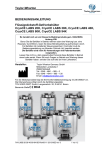
1
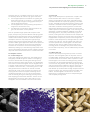
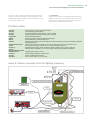
https://riskengineering-services.hdi-gerling.com
HDI-Gerling Risk Engineering Service
Risk Engineering
Guideline
int
er
na
tio
na
l
Fire protection and
fire-fighting in silo
and bin installations
Proper planning and the
right measures in case of
fire allow controlling silo
fires.
Silo fires are special fires and require special
measures from operating companies, fire brigades
and specialist consultants.
1 General
Insufficient preventative fire protection and ignorance of
special circumstances to be observed in case of fire make
fires in silos and closed bin installations the origin of major
material loss and personal injury again and again. Conventional extinguishing agents and methods are hardly suitable for reliable silo fire fighting and for avoiding dust
explosions. The dust explosion hazard is particularly high
when attempting to clear the material out of a silo loaded
with hot spots or glowing nests. The difficult access, the
building height, the dust explosion hazard of the combustible bulk material, the required special fire-fighting agents
and the enormous amount of time needed make silo fires
special cases of fire-fighting. Such fires can be controlled
only when suitable preparation, coordinated fire-fighting
and patience are provided.
2 Risk situation and examples
of losses
2.1 Risk situation
Silos, closed bins and similar large-scale containers serve
for storing loose bulk material. The container sizes are
quite different and may reach up to several thousand cubic
metres. Silos can be made of steel, concrete, plastics (GRP),
wood or textile materials. Loose bulk material can be available in the following conditions:
• as dust (e. g. fibre dust, plastic powder)
• as grains (e. g. cereals, plastic pellets)
• as lumps (e. g. coal, potatoes)
• as mush (e. g. mud)
• as machined pieces (e. g. wooden chips)
• as shredded pieces (e. g. plastic waste)
Ignition sources frequently include self-ignitions or introduced sparks and glowing nests. Organic bulk materials
(e. g. food and fodder) may tend to self-ignition when
Risk Engineering Guideline:
Fire protection and fire-fighting in silo and bin installations
stored too long or in conditions that are too moist or too
hot. Basically solid bulk material may ignite itself when:
• the storage temperature is sufficient for igniting the
existing bulk volume or vice versa, i. e. when the bulk
volume is large enough for being ignited at the prevailing storage temperature,
• the storage duration at the prevailing temperature is
longer than the induction time,
• the discharge of combustion gases and feed of oxygen into the reaction zone is possible.
Fires can spread through operational transport routes
(pipes, conveyor lines), thermal radiation and flying sparks.
Smouldering and pyrolysis gases may be generated, even
outside of the container, which can create an explosive
atmosphere. Flash fire may escape through openings.
Opening the container and evacuating the bulk material
involves a ladder ignition/explosion hazard. Dust explosions
may occur even outside of the silo due to dust deposits.
The statics of the container and of the building may be
affected by heating-up of load-bearing components and it
may be overloaded by fire water and fail. Swollen materials
may make the container burst when in contact with water.
2.2 Examples of losses
2.2.1 Fresh tankage silo
A 30 t fresh tankage silo catches fire, presumably due to
biologically induced self-ignition. When no fire-fighting
success is achieved after actuating the existing manual
CO2 fire protection system several times, it is decided two
hours later to call the fire brigade. The fire brigade calls in
a nitrogen tanker. Before the tanker arrives, silo discharge
is started. A short time later, a "whooshing noise" is suddenly perceived from inside the silo. Flames of several
metres length come out of the upper silo manhole, destroying the silo and the conveyors and setting the surrounding storage hall on fire. It must be assumed that
fresh air entering during the discharge process (product
level dropping) has started the flash fire. The fire can be
extinguished only one hour later, after calling in more
fire-fighters. The loss suffered is more than one million.
2.2.2 Coal silo
Slight smoke development is perceived on a 3,000 t reinforced concrete hard coal silo on the site of a power
station. The temperature and carbon monoxide sensors
provided inside the silo respond by signalling a smouldering fire. The fixed foam-type fire protection system on the
silo head is activated and also the fire brigade is called in
and smoke is reduced. Assuming that the fire has been
extinguished, discharging the silo starts some hours later
under supervision of the fire brigade. In the morning of the
second day, a powerful explosion suddenly occurs while
discharging the silo, very likely intensified by ingress of
fresh air, making the 250 t concrete silo roof collapse and
destroying the conveyors on the silo head. The silo was not
equipped with an explosion pressure relief arrangement.
Provision of this safety feature, although obvious, is often
missing from coal silos. The fire brigade now orders the
silo to be opened with a wrecking ball. This work takes
another six days. The silo suffers total loss and the surrounding plants are damaged. The power station had to
be shut down temporarily. The loss suffered was just under
€ 10 million.
2.2.3 Wood chips silo
Smoke is seen escape through the top hatch of a wood
chips silo. The fire brigade opens the top hatch from its
turntable ladder and detects heavy smoke generation, but
no flames. Now the silo bottom hatch is opened in order
to discharge the silo content and extinguish any possible
fire pockets. The fire brigade discharges the wood chips
out of the silo using shovels, with the chips getting darker
and soon totally black. Suddenly a flash fire comes out of
the bottom hatch and injures a fire-fighter. Presumably
dust whirled up combined with the high temperatures and
ingress of oxygen upon opening caused this sudden combustion. The fire brigade is on the site for more than
twelve hours in total before the silo is finally discharged
and completely extinguished.
3
4
Risk Engineering Guideline:
Fire protection and fire-fighting in silo and bin installations
2.2.4 Cereals silo
An explosion occurs while fighting a fire on a cereals silo,
making the concrete roof of the eleven-storey silo collapse
and killing two fire-fighters. Another six fire-fighters are
seriously injured. The operator is sentenced to several years
of prison for lack of preventative fire protection.
3 Terms
Operating instructions
The operating instructions (in the sense of Safety Information) are instructions issued by the employer to the employees. They define the behaviour on the site regarding
workplace and work and aim at avoiding accidents and
health hazards. In addition, the operating instructions
serve as a basis for training.
A distinction is made between operating instructions describing how to handle hazardous substances and operating instructions describing how to operate machinery and
plants. Only hazardous and/or safety-relevant work processes are dealt with. To this end, the operating instructions contain the necessary information provided in the
user manual (for technical products) or the safety data
sheets (for hazardous substances) issued by the producer,
importer or supplier.
Explosion pressure relief
Pressure relief devices serve for discharging the excess
pressure in a well-designed way in the event of an explosion in order not to endanger the stability of a silo or a bin.
The required pressure relief surfaces and container stability
values can be calculated from the specifications in VDI
3673 or DIN EN 14491. In an explosion and when the
pressure relief system responds, persons must not be endangered by ejected or falling parts and by possible effects
of pressure and flames.
Inert gas
Low-reactivity gases (participating in few chemical reactions only) are referred to as inert gases. However, it depends on the specific case whether a given gas is referred
to as inert gas for a given application. Examples of inert
gases are nitrogen and all noble gases, i. e. argon and
helium.
Inert gases in the sense of fire and explosion protection
can basically be all non-combustible and non-oxidizing
gases not reacting with the substance and/or the dust,
e. g. nitrogen, carbon dioxide and argon.
Inertness
To create inertness means filling a volume with an inert
gas (in the sense of fire and explosion protection) in order
to displace oxygen so that combustion/explosion inside this
volume is no longer possible.
Spray water system
Spray water systems serve for feeding fire water to the fire
in a very well-designed way. This can be achieved by a dry
pipe fire protection system with signalling to the fire brigade or by pipes that are permanently connected to the
water supply and activated either automatically or manually in case of fire.
Safety parameters
Safety parameters is a collective term for substance properties of combustible dust according to VDI 2263 sheet 1.
4 Operator obligations
The obligations of operators of silo and similar facilities
include among others analysis and documentation of possible fire and explosion hazards and taking the necessary
safety measures. This is done using a risk analysis that the
operator must carry out prior to putting the facility into
operation for the first time. The essential element is to
consider all operating conditions, starting with construction, putting into operation, operation, maintenance and
Risk Engineering Guideline:
Fire protection and fire-fighting in silo and bin installations
cleaning up to dismounting and disposal. As far as explosion hazards are concerned, the Operational Safety Decree
applies in particular. An explosion protection document
applying to the facility must be prepared. Operating instructions must show the employees the correct and safe
operation of silo and bin facilities and the proper behaviour in case of danger.
Rating of the fire and explosion risk must consider that
organic material dust may always be combustible and/or
enable a dust explosion. More details in specific cases can
be obtained from the safety data sheets, from databases
for safety parameters, safety literature and laboratory tests.
Dust may be generated even from lumpy or shredded
material, following abrasion inside the silo, in the surroundings and in the conveyor systems, possibly causing a
dangerous dust explosion. When changing to storage of
another material, a new fire and explosion hazard analysis
must be carried out.
The operator obligations also comprise having fire protection systems and electric installations including the lightning protection systems, Operational Safety Decree/explosive atmospheres, Technical Inspection Rules, Insurer's
Inspection Regulations etc.) inspected and maintained at
regular intervals.
5 Protective measures
A series of tried-and-tested preventative and fire protection measures can be taken that can prevent a silo fire or
minimise its consequences:
5.1 Avoiding fire loads and ignition sources
Throwing the product into the silo may whirl up dust,
especially during filling. If an ignition source is present, a
dust explosion may result.
Additional fire loads from dust deposits near the silo must
be kept to a minimum by regular cleaning. Ignition sources
inside the silo and around the silo must absolutely be
avoided.
5.1.1 Avoiding introduction
A cell occupation and control schedule can avoid mixtures
and critical conditions can be identified and traced. This
can reduce the risk of self-ignition inside the silo, e. g. due
to introduction of moisture. The moisture content of
stored materials tending to self-ignition in connection with
moisture should be examined before storing. Silo ventilation can serve for keeping the moisture content of the
stored material low.
The formation of hot of burning material, glowing nests
and sparks and/or spark-generating parts must be avoided
efficiently as early as in the conveyor systems to the silo.
Safety monitoring of conveyors (off-track monitors, slip
control, speed measurement and temperature control) as
well as metal separators serve this purpose.
Transportation of hot or burning substances (e. g. glowing
nests) by conveyors to the silo must be effectively prevented. To this end, infrared sensors (hot spot sensors) or spark
detectors can be employed. However, these make sense
only if after detecting a hot or burning substance, this
substance is either reliably discharged automatically or
extinguished or the conveyor system is shut down immediately. Spark extinguishing systems have proved their worth
for extinguishing substances in conveyors. The decisive
aspect here is that the bulk density within the conveyor
system is not too high, covering up glowing nests and
sparks, and that the stored material is not too sensitive to
water. Soiling of spark sensors can be removed e. g. by
compressed-air cleaning of the optical units. These reasons
among others necessitate that design and installation are
by a VdS-approved spark extinguishing systems company
in accordance with VdS guideline 2106.
5.1.2 Ignition sources on and in the silo
When an explosive atmosphere is specified inside the silo
(so-called explosion zones, see Operations Guideline
1999/92/EC), electric and non-electric devices and systems
in Europe must meet the requirements of ATEX Product
Guideline 94/9/EC (explosion-protected equipment).
5
6
Risk Engineering Guideline:
Fire protection and fire-fighting in silo and bin installations
Similar laws and regulations govern the purchasing requirements outside of Europe. These must be regularly
checked by a capable person according to the Operational
Safety Decree every three years at the latest.
Electric installations (e. g. lights) should not be installed
inside the silo if possible. All electric equipment (including
lighting fixtures) in explosive atmospheres must be suitable
for use in explosive atmospheres and arranged so that they
cannot be covered up with material. See also EN IEC 60079
"Explosive atmospheres". Conductive silo cells must be
earthed or connected to equipotential bonding to counteract static electricity (see VDE standards). Static electricity
may also occur in filling and conveying operations and
when pouring substances into another container. Such
processes require equipotential bonding measures as well,
especially including the vehicles connected with operational facilities, such as lorries and railway wagons. See
also NFPA 77 and Cenelec CLC/TR 50404.
High silo buildings should be equipped with a lightning
protection system according to DGUV Information 209045 (former BGI 739-2). This system must be completed
in accordance with DIN EN 62305/VDE 0185-305.
5.2 Permanent inertness
In case of bulk material with a heavy self-ignition tendency
such as some hard coal grades or coal dust, operation of
the silo and bin facilities in a permanent inert gas atmosphere is recommended. A constant feed of inert gas
(usually nitrogen) keeps the silo atmosphere permanently
below a critical oxygen concentration which is between 2
and 12 % by vol., depending on the bulk material. This
avoids a fire from the start, but inert gas escaping during
silo filling and draining processes must be permanently
replaced. This may cause considerable costs.
5.3 Design measures for explosion protection
This comprises all measures involving well-aimed discharge
of excess pressure which avoid damage to the silo body
and the (pneumatic) conveyors in case of a dust explosion.
Dust explosions can create an excess pressure level of up
to 8 bars. Pressure relief must be to the outside and without any hazards. If this is not possible, technical measures
must be taken that enable safe control of the excess pressure (e. g. quenching unit). The examples listed below
describe some possible measures that must be defined in
a protection concept and matched to one another.
The most frequently applied measure is to provide explosion pressure relief areas on the silo head, e. g. by installing rupture discs, rupture flaps or breaking films which
relieve the pressure either to the top or laterally. The silo
containers must be designed to withstand the reduced
explosion pressure resulting from the pressure relief. The
size of the necessary pressure relief areas is calculated
among others as a function of the dust explosion hazard
of the substance (KSt value) and of container shape and
size. Precise calculations can be found in VDI guideline
3673 or in DIN EN 14491.
Mechanically closed conveyors such as elevators can also
be protected by pressure relief units such as rupture discs
and pressure relief flaps. In that case, the conveyors must
be designed to withstand the reduced explosion pressure.
Picture 1: Examples of rupture discs
Pneumatic conveyors may be protected by so-called explosion diverters. In such a unit, the conveying direction of the
material to be transported is redirected at an acute angle
so that the main excess pressure direction can be relieved
through a rupture disc arranged in the direction of transport.
All conveying systems must withstand the reduced explosion excess pressure when pressure relief units are provided.
To prevent transmission of dust explosions to other silo
cells or conveyor systems, the individual units must be
isolated from one another from an explosion protection
point of view. To achieve this, rotary valves or explosion
diverters are usually installed. Special explosion protection
valves and quick-acting gate valves for pneumatic conveyors which close within fractions of a second are also available. In such a configuration, the conveyor systems must
withstand the full or the reduced (if pressure relief is provided) explosion pressure. In addition, explosion suppression systems can be installed that suppress a starting explosion by spraying in an extinguishing agent (extinguishing powder, water) very quickly. When used for isolation
purposes, these systems are referred to as extinguishing
agent barriers. Even conveyor systems equipped with extinguishing agent barriers or explosion suppression systems
must be designed to withstand a reduced explosion excess
pressure.
5.4 Structural fire protection
Silos and bins must be stable and sufficiently strong according to the general technical rules. Dimensioning must
take explosion protection measures into account (arrangement, size, static response pressure and load relief capability of pressure relief units and container strength for reduced explosion pressure).
Risk Engineering Guideline:
Fire protection and fire-fighting in silo and bin installations
Picture 2: Prepared sealing for clearing-out of silo
Silo and bin facilities should be built from non-combustible
building materials in order to avoid additional fire loads.
Solid silo facilities made of brickwork or reinforced concrete offer the benefit that they resist a fire well and offer
good stability. Silos made of metal, plastic (GRP) or textile
materials, however, will quickly lose their stability in case
of fire and may collapse. The statics may quickly fail in
particular when filling fire water into such silos. Moreover,
the electric conductivity should be ensured for silos made
of plastics (protection against sparks due to electrostatic
charges).
Silo and bin facilities should be separated with a fire rating
inside buildings and with respect to other buildings and
plant components. When setting up silos and bins outdoors, a minimum distance from buildings and plants of 5
m and of 10 m in case of combustible silos should be respected, especially if the silo body is not solid and there is
a high danger of collapse. When setting up silos and bins
inside buildings, the walls and ceilings of the building
should be fire-resistant (F90 according to DIN 4102). As for
the rest, the minimum requirements of DGUV Information
209-045 must be met.
Essential inertness of the silo in case of fire necessitates
that all openings can be made as gas-tight as possible
(even temporarily) so that the inert gas cannot escape
quickly.
As far as the subsequent clearing-out of the silo is concerned, access hatches at different silo body elevations
(inside diameter 0.60 m min.) and additional emergency
clearing openings at the silo base have proved their worth;
from there the stored material can be transported to a safe
area and extinguished if necessary.
Special requirements on the condition of silos and bins and
their surroundings may apply to the storage of special bulk
materials due to provisions imposed by authorities or employer’s liability associations. See also chapter 8.
5.5 Fixed fire protection
These measures are to serve for detecting and/or fighting a
fire.
5.5.1 Silo monitoring
In addition to the usual technical monitoring equipment
such as level indicators and overfilling protections, silos
and bins should also be monitored for internal fire. The
simplest measure frequently involves permanently installed
temperature sensors or measuring lances provided at different elevations of the bulk material. However, their disadvantage is that they react quite slowly or do not detect
the fire at all and that experience tells us that before they
respond, smoke can already be seen escaping from the
silo.
Smoke detectors detecting typical smouldering gases (e. g.
carbon monoxide CO and methane CH4) very early are
better suited for this purpose. Depending on the material
stored, a high carbon monoxide concentration is frequently found inside a silo (holding e. g. coal or wood pellets)
plus air humidity and fine dust so that smoke detectors
detecting CO exclusively can be used only with restrictions.
Oxygen sensors may also serve for fire monitoring.
Conventional smoke sensors are less suited inside the silo
as they soil quickly. They can be installed in spaces above
the silo tops if required, and possibly as smoke intake systems as far as the amount of dust produced is low. Special
filters and dust separators for smoke intake systems have
been developed for use especially inside silos so that now
smoke monitoring is possible, depending on the material
stored. In open bin facilities, stationary thermal image
cameras are often suitable for early fire detection.
At any rate, the automatic monitoring concepts must be
adapted specifically to the local conditions. Engineering
design by a specialist is required because incorrect selection of equipment and wrong locations of fire alarms may
7
8
Risk Engineering Guideline:
Fire protection and fire-fighting in silo and bin installations
result in system trouble, false alarms or failure to respond/
general failure. Universal monitoring systems that can be
used for silos without restrictions are not available so far.
5.5.2 Fixed fire protection systems
5.5.2.1 Inertness in case of fire
The most favourable option for fire-fighting and safe clearing-out in case of fire is inertness of the silo or bin. In this
process, an inert gas (nitrogen in most cases) is fed into
the silo or the bin so that the air and consequently oxygen
is displaced from the silo and the oxygen content drops
below 4-6 % by vol. At this oxygen concentration, fire
spread in the usually stored materials is no longer possible.
Dust explosions of organic materials (food and fodder,
wood, coal and plastics) are no longer possible as early as
below 8 % by vol. (oxygen limit concentration). The oxygen limit concentrations depend on the material and are
between 3 % by vol. (magnesium) and 14 % by vol. (hard
coal), see table 1. In case of fire, you should subtract at
least 1 % by vol. from the values in the table as a safety
margin.
Nitrogen as an inert gas offers the advantage that it is a
little more lightweight than air and non-toxic (but it displaces oxygen!). It is true that carbon dioxide has slightly
better fire-fighting properties, but is toxic in higher concentrations and above all is heavier than air, thus accumulating in lower-level rooms. This may become dangerous
for fire-fighters in an inert silo if the inert gas feed point is
below ground level or carbon dioxide escapes from other
silo leaks and accumulates beneath the silo. In addition, it
may react to produce explosive carbon monoxide at very
high temperatures.
To achieve well-designed and rapid inertness of a silo or
bin, involves fitting permanently installed gas pipes to the
silo top and closing gas feed and measuring sensor connections (gas, pressure, ø approx. 15 cm). A C-pipe connection (DIN 14302) as a nozzle or annular channel is useful for gas feeding and the pipe should be installed so that
it cannot be clogged by the bulk material. The inert gas
connections should be provided at the top and the bottom. Suitable sealing fixtures shall be provided for the silo
top and bottom area.
At least three closing 1/2" openings should be provided
for measuring sensors; these should be located at the silo
bottom (between the discharge and the inert gas feed), at
half the silo elevation and at the silo top. In addition a
ventilation opening should be provided at the silo top in
order to discharge displaced air.
Picture 3: Examples of explosion-proof smoke detectors
Picture 4: Smoke detector in a practical application
Risk Engineering Guideline:
Fire protection and fire-fighting in silo and bin installations
5.5.2.2 Spray water systems
The installation of stationary spray water systems inside
silos and bins is recommended for bulk materials that can
well be extinguished with water, e. g. wood chips and dust
as well as paper chips and dust. Design and installation
must comply with VdS guideline 2109 (Spray water systems) and as far as wood is concerned, DGUV Information
209-045. The water applied should be at least 7.5 mm/min
(l/m² x min). Activation may be either manual or automatic,
e. g. by an activation pipework (frequently seen in bins) or
by automatic fire alarms. The fire protection systems of
smaller silos may also be installed as dry, semi-fixed sys-
tems supplied by fire water from hose reels or by the fire
brigade in case of fire.
Filter systems using textile components in suction systems
should also be fitted with manual, automatic or semistationary spray water systems.
Electric fire water booster pumps must be relied upon in
the event of a fire and should therefore be connected to
an emergency power supply.
5.5.2.3 Gas protection systems
Gas protection systems are suitable for silos and bins only
with reservations. The working principle relies on inertness.
Example:
Silo dimensions:
height: 40 m, diameter: 8 m
Silo cross-section area:
4 m x 4 m x π (3.14) = 50 m²
Total silo volume:
50 m² x 40 m = 2,000 m³ (organic material)
Filling level:
24 m (= 60 %), i. e. 800 m³ of empty top space,
1,200 m³ of bulk material
Substance
Limit oxygen concentration with nitrogen
inertness in % by vol.
Aluminium
5
Brown coal
12
Cellulose
9
Inert gas quantity in top space:
800 m³ x 1.5 m³ of nitrogen/m³ = 1,200 m³ of nitrogen
Wood
10
Inert gas quantity of bulk material:
1,200 m³ x 0.5 (1.0) m³ of nitrogen/m³ = 600 (1,200) m³ of
nitrogen
Magnesium
pre-alloy
3
Feed rate in top space:
1,200 m³/4 hours = 300 m³/h
Maize starch
9
Feed rate in bulk material:
600 (1,200) m³/4 hours = 150 (300) m³/h
Polyacrylnitrile
10
Polyethylene (PE)
10
Carbon black
12
Hard coal
14
Plus more inert gas for maintaining the concentration (leaks, depending on the silo in question).
Table 1: Limit oxygen concentrations of various
dusts; from VDI 2263-2
Picture 5: Inert gas delivery by tank lorry with a mobile evaporator
9
10
Risk Engineering Guideline:
Fire protection and fire-fighting in silo and bin installations
However, the technical effort required is quite considerable
because the entire extinguishing gas quantity needed must
be stored. As compared with conventional gas protection
systems, the flooding periods are much longer (roughly
one to two hours). The goal of keeping the extinguishing
and/or inert gas inside the silo during many hours or days
cannot be achieved by using gas protection systems alone.
A continuous inert gas feed during an extended period of
time is required because silos are usually not 100 % gastight and the extinguishing and/or inert gas will slowly
escape.
5.6 Fire water supply
Sufficient water supply is necessary for initial measures,
for cooling building parts, for feeding existing fire protection systems and for extinguishing cleared-out glowing
nests. The fire water supply should be at least 192 m³/h
(= 3,200 l/min) for two hours duration. When fixed fire
protection systems are involved, an independent fire water
supply must be sized in accordance with the design and
kept available.
For manual fire-fighting at the silo top, a (dry) riser which
can be fed from a safe area in the ground floor should be
available in the silo building for the fire brigade. This riser
can also be used for inertness (upward gas transport). This
pipe must be equipped with C- and/or B-couplers according to DIN 14 302 and should have a diameter of at least
DN 65 (or even larger, depending on the situation). All
pipes must be earthed for protection against electrostatic
charges (connection to equipotential bonding).
5.7 Fire protection organisation
According to the Operational Safety Decree, an explosion
protection document must be prepared and updated for
stored materials that are susceptible to dust explosions. All
inspections required by the Operational Safety Decree must
be carried out at regular intervals.
Operating instructions should be prepared for work near
silos and bins (entry permit, cleaning schedule etc.). No hot
work is allowed near silo facilities and inside the silo, or
increased safety measures must be taken, with the silos
being completely empty and cleaned (free of dust). See
also the Technical Safety Information on the subject-matter
of "Hot work“. Smoking is not allowed. This ban must be
clearly communicated by means of signs.
A sufficient number of employees must be instructed in
how to act in case of a silo fire and in the handling of the
safety equipment in the silo and bin facilities. Practical fire
extinguisher training using a training unit is also strongly
recommended.
An alarm plan should indicate who must be informed in
case of fire, e. g. company management, fire brigade, inert
gas supplier, technical advisor, employer's liability association, trade supervision, fire insurer (fire protection dept).
The inert gas suppliers must be contacted in order to find
out which suitable gases and quantities as well as necessary equipment (evaporator) can be supplied within which
time.
The practical fire-fighting measures must be discussed in
advance with the fire brigade in charge and regular exercises must be performed!
Fire brigade plans providing the necessary information
and design documents of the silo and bin facilities as
well as the present Technical Safety Information should
be handy on site for the fire brigade and for technical
advisors/experts.
5.8 Maintenance
Regular maintenance of filters, moving parts including
bearings and hinges and the existing safety equipment of
the silo and bin facilities according to the manufacturer's
specifications is urgently required.
6 Measures in case of fire
After notifying the offices in charge (fire brigade, technical
advisor), in case of fire all conveyors should be shut down
and to prepare inertness, closing all silo openings as gastightly as possible should be started, if necessary using wet
bags, panels, adhesive tape or similar things. This avoids
further oxygen ingress. In this process, it must be ensured
that no persons are endangered by smoke and if required,
respiratory equipment must be worn (fire brigade). In addition, further adjoining silos not affected by the fire should
be emptied if possible in order to avoid fire spread.
6.1 Inertness
The inert gas quantity required must be calculated and
made available. The process to achieve inertness should
only be started when enough inert gas is available and
further supply is ensured.
Moreover, continuous gas measurements are required,
among others:
• oxygen in order to prove sufficient inertness,
• CO: determination of fire intensity and fire-fighting
success.
• the measured values (course) must be assessed on
site by an expert.
6.1.1 Required inert gas quantities
As practical experience has shown, achieving an inert empty silo top space requires 1 m³ of carbon monoxide (gaseous) or 1.5 m³ of nitrogen (gaseous) per m³ of empty top
space. This reduces the oxygen concentration to less than
8.0 % by vol. so that there is no more dust explosion hazard for organic substances in the top space. A four-hour
period is aimed at for feeding in the corresponding inert
gas quantity.
Feed rates of 0.5 to 1.0 m³ of inert gas (gaseous) per m³ of
bulk material reduce the oxygen content to < 2 % by vol.
This is necessary for extinguishing the glowing fire within
the bulk material and must be maintained during an extended period (usually 48 hours). Here as well, an inert gas
feeding period of four hours is aimed at.
The precondition in each case is that the silo is relatively
gas-tight and/or can be sealed (temporarily); otherwise the
Risk Engineering Guideline:
Fire protection and fire-fighting in silo and bin installations
inert gas quantities needed may be substantially larger. In
addition, the actual silo filling level should be checked,
regardless of automatic level indicators which may occasionally be defective or imprecise.
6.1.2 Storage and purchasing of inert gas
Inert gas can be ordered as an emergency supply from
major gas suppliers. However, several hours may pass until
the gas delivery arrives at the silo in question. This is uncritical in most cases because a smouldering fire inside the
silo spreads only very slowly and there often is no other
promising fire-fighting method available anyway (depending on the material stored). All persons involved must be
prudent and above all patient!
sioned evaporator unit. Nitrogen cylinder bundles, however, can be used continuously until completely empty (this
does not apply to CO₂ cylinders!).
In an optimum configuration, inert gas can also be stored
in the operations, e. g. in cylinder bundles or liquefied gas
tanks (with evaporators). In this way the process of achieving inertness in a silo or a bin can be started early in case
of fire and continued by gas delivered later. The gas quantity to be stocked depends on the silo size. It should be
sufficient for creating inertness for four hours. In the example above and when supposing an unfavourable filling
degree of only 10 % of the silo volume, there would be
1,800 m³ of empty top volume so that 1,800 m³ x 1.5 m³
of nitrogen/m³ = 2,700 m³ of nitrogen would be required
(equalling around 3,160 kg).
Both cylinder bundles (gaseous inert gas) and tank lorries
(liquid inert gas) can be delivered. One road tanker with
6.1.3 Task of inert gas and fire extinguishing
20,000 kg of liquid nitrogen on a semi-trailer yields around
As a basic rule, the top space should be made inert first.
17,100 m³ of gaseous nitrogen. A drawback of tanker
This serves as a protection against possible dust explosions
deliveries is that the inert gas
in the empty top volume, which
Incomplete fire-fighting and early clearing-out
can be withdrawn from the
has priority for the time being.
of a silo often results in dust explosions – with
tank in gaseous condition
However, feeding in inert gas
fatal consequences!
only during the first roughly
from the top alone (opposed to
three hours (and the residual
the thermal lift) usually cannot
pressure must not drop below 0.5 bar). After that, evapopenetrate the bulk material in the silo and therefore not
ration from the liquid to the gas phase is needed which
completely extinguish the glowing fire, which, in turn, is a
can be realized only with a separate and suitably dimenprecondition for clearing out the silo without hazards. In
Guideline values for silo inertness/overview
Remarks
Oxygen concentration against dust explosion
(Limit oxygen concentration)
< 8.0 % by vol. for organic material on average
Applies to clearing-out of the silo; in this
process, measure the oxygen at the silo bottom
and top.
Oxygen concentration (O₂) against fire spread
4-6 % by vol. O₂ max.
Measure the oxygen at the silo top
Maintain this concentration for at least 48 h.
Oxygen concentration (O₂) for extinguishing
< 2 % by vol. O₂
Measure the oxygen at the silo top
Maintain this concentration for at least 48 h!
Inert gas feed quantity in top space for oxygen
concentration < 8 % by vol.
1.0-1.5 m³ per m³ of empty silo volume
N₂: 1.5 m³/m³ of empty volume
CO₂: 1.0 m³/m³ of empty volume
Inert gas feed quantity in bulk material for
oxygen concentration < 2 % by vol.
0.5-1.0 m³ per m³ of bulk material volume
Regardless of inert gas!
Tank lorry load
(liquefied nitrogen)
(liquefied carbon dioxide)
approx. 20,000 kg (liquefied)
= approx. 17,100 m³ N₂ gas
= approx. 10,820 m³ CO₂ gas
An evaporator is required!
Max. internal silo excess pressure
See manufacturer's specifications
Depending on design; to be measured near the
inert gas feed point.
Measuring of fire intensity (glowing fire)
Measure the carbon monoxide (CO) concentration
at the silo top
Decreases from >> 1.000 ppm to <100 ppm,
possibly to 0 in case of successful inertness.
Table 2: Practical guideline values for silo inertness
11
12
Risk Engineering Guideline:
Fire protection and fire-fighting in silo and bin installations
the second step, inert gas is therefore also fed in at the silo
bottom at the same time, e. g. using a prepared connection (C-coupler according to DIN 14302), a lance or an
outside ring line with openings protruding into the silo.
The oxygen concentration must be permanently measured
in the silo top and bottom area.
Gas feeding at the bottom must be slow and at low pressure so that the gas penetrates the bulk material evenly
and no major channels form inside the bulk material. The
oxygen displaced from the bulk material ends up in the
previously inert top space. Depending on the oxygen concentration in the silo top, gas feeding from the top can be
reduced slowly and finally shut down altogether. However,
should the oxygen concentration in the top space rise
above e. g. 8 % by vol. again (in case of organic material),
inert gas must again be fed in from the top.
Prior to filling the filling lines with the inert gas, these lines
must be vented and/or flushed with the inert gas so that
no additional oxygen is blown into the silo.
The process of creating inertness must be monitored by
measurements. The parameters below must be measured
on the silo top:
• oxygen concentration
• carbon monoxide concentration
• temperature inside the silo if required
• carbon dioxide concentration if required
The pressure inside the silo must be monitored at the silo
bottom near the inert gas feeding point.
If the necessary connections and openings are not provided on the silo, these must be made available temporarily, if necessary by drilling holes into the silo (only in the
bulk material area and while using water for drill cooling).
In this process, explosion protection must be observed.
Igniting sparks and hot surfaces must absolutely be avoided. The filling and extinguishing process may take from
several hours to some days. The CO concentration is used
to determine if the fire has been extinguished. A permanent CO concentration of < 30 ppm after finishing the
inertness process (no more inert gas feeding) indicates
successful fire-fighting.
6.2 Use of water/foam
Fire water with wetting agent, medium- and high-expansion foam or extinguishing gel can be applied for cooling
and/or covering up the bulk material under inert gas protection. The use of fire water and foam inside the silo is
usually impossible if the substances in question are swollen
or if the bulk material will not impregnate well with water,
forms lumps or the silo is made of metal, plastics or textile
materials and will not tolerate increased weight due to
water (danger of collapse). The use of fire water without
additives (full jet/spray jet) inside the silo should be avoided. When using water near the silo, ensure that no dust is
whirled up (use a spray jet) and that the water will not
flow into silo cells.
Silo cooling from the outside using water is usually possible and makes sense.
6.3 Clearing-out of silo
Clearing out of the silo may be started only after the fire is
completely extinguished. The CO concentration is used to
determine if the fire has been extinguished. A permanent
CO concentration of < 30 ppm after finishing the inertness
process (no more inert gas feeding) indicates successful
fire-fighting. If the fire cannot be extinguished, the silo
must be cleared out under an inert atmosphere both inside
the silo and in the associated conveying systems.
The decision about when to start clearing out must be
made by an expert in cooperation with the fire brigade.
Failure to observe this procedure involves the danger of
another fire or a dust explosion while clearing out the silo!
A glowing fire may have created so-called bridges inside
the silo which may collapse while clearing out the silo and
whirl up dust. A dust explosion may follow if there is no
more inert atmosphere.
Before starting clearing-out, the absence of dust must be
ascertained in the spaces connected with the silo and if
required, these must be cleaned. Raising dust must absolutely be avoided in this process.
While discharging the bulk material, suitable measures
must be taken to avoid the formation of hazardous dust/
air mixtures even outside the silo, e. g. by applying a water
curtain.
Risk Engineering Guideline:
Fire protection and fire-fighting in silo and bin installations
Picture 6: Tank trailer and mobile evaporator
Picture 7: Stationary evaporator next to a silo
Pictures 8a+b: Inert gas delivery
Picture 9: Inert gas connection to stationary evaporator
Picture 10: Inert gas feeding through pre-installed pipes
13
14
Risk Engineering Guideline:
Fire protection and fire-fighting in silo and bin installations
7 Emergency addresses
7.1 Inert gas suppliers
Suitable inert gas suppliers can be found on the homepage
of the Industriegaseverband (IGV) www.industriegaseverband.de. An extract is shown below (no responsibility is
accepted for the correctness and completeness of the
information, as per 02/2012):
In case of fire, the fire brigade control stations can offer
assistance in procuring inert gas.
Company
Address
Phone
Fax
E-Mail/Internet
Hauptstelle für das
Grubenrettungswesen
Wilhelmstraße 98
D-44649 Herne
49-2325-593-333
-
www.atemschutzzentrum.net
Air Liquide Deutschland GmbH
Hans-Günther-Sohl-Straße 5
D-40235 Düsseldorf
49-211-6699-222
[email protected]
www.airliquide.de
Linde AG
Gases Division Germany
Seitnerstr. 70
D-82049 Pullach
49-211-6699-0
After 6:00 p.m. an answering
machine is running, providing an
emergency number
49-1803-85000-0
Emergency call no.: (outside of
business hours) 49-89-7446-2333
-
[email protected]
www.linde-gas.de
AIR PRODUCTS
GmbH
Rensingstr. 15
44807 Bochum-Riemke
49-234-6105-60
Emergency call no.: (outside of
business hours) 49-69-50985368
49-234-6105-6371
www.airproducts.de
KRAISS & FRIZ
Autogenwerk
Bahnhofstraße 64
D-73630 Remshalden
49-7151-709966-0
Only in Baden-Württemberg
(Postcode 7....)
49-7151-709966-22
[email protected]
www.kraissundfriz.de
PRAXAIR
Kennedyhaus
Hans-Böckler-Str.1
D-40476 Düsseldorf
49-211-2600-0
49-211-2600-123
[email protected]
www.praxair.com
WESTFALEN AG
Industrieweg 43
D-48155 Münster
49-251-695-0
Emergency call no.: (outside of
business hours) 49-5459-80625
Equipment: 49-251-695-228
49-251-695-194
[email protected]
www.westfalen-ag.de
BASI SCHÖBERL
GmbH & Co. KG
Im Steingerüst 57
D-76437 Rastatt
49-7222-505-0
49-7222-505-298
[email protected]
www.basigas.de
MESSER GROUP
GmbH
Messer-Platz 1
D-65812 Bad Soden
49-6196-7760-0
49-6196-7760-442
[email protected]
www.messergroup.com
RIEßNER-GASE
GmbH & Co.KG
Rudolf-Diesel-Str. 5
D-96215 Lichtenfels
49-9571-765-0
Emergency call no.:
49-173-8877930
49-9571-765-67
[email protected]
www.riessner.de
Emergency call no.: (outside of
business hours) 49-180-201-0000
7.2 Experts
In case of fire, the Zentrum für Brand- und Explosionsschutz (Fire and explosion protection centre) of DMT
GmbH & Co. KG in Dortmund can be contacted among
others, Emergency phone no.: 49-231-5333-237 (available
24 h a day, by return call), www.dmt.de
This office can send experts and measuring equipment to
the site in question.
TUIS Emergency call centres/the control stations of these TUIS member companies are available around the clock
BASF SE, Ludwigshafen
49-621-6043333*
BASF Schwarzheide GmbH, Schwarzheide
49-35752-62112
Currenta GmbH & Co. OHG, Leverkusen
49-214-3099300¹
Dow Deutschland Anlagengesellschaft mbh, Stade
49-4146-912333
Henkel AG & Co. KGaA, Düsseldorf
49-211-7973350
Infracor Gmbh, Chemiepark Marl
49-2365-492232
InfraLeuna GmbH, Leuna
49-3461-434333
InfraServ GmbH & Co. Gendorf KG, Gendorf
49-8679-72222
Infraserv GmbH & Co. Höchst KG, Frankfurt am Main
49-69-3056418
Merck KGaA, Darmstadt
49-6151-722440
Bayer Schering Pharma AG, Berlin
49-30-46814208
Wacker Chemie AG, Burghausen
49-8677-832222
*National Response Centre ¹for CHEMPARK Leverkusen, Dormagen, Krefeld
In Europe, the International Chemical Environment (ICE) is available for information, see http://helid.digicollection.org/en/d/Js13467e/11.2.html
Risk Engineering Guideline:
Fire protection and fire-fighting in silo and bin installations
If the silo or bin in question holds chemical products, you
may also contact the Transport-Unfall-Informations- und
Hilfeleistungssystem (Transportation and accident information and help system) TUIS.
7.3 Contribution
The Zentrum für Brand- und Explosionsschutz (Fire and
explosion protection centre) of DMT GmbH & Co. KG in
Dortmund has actively contributed to the content and
layout of the present Safety Information.
8 Further reading
VdS 2154
VdS 2106
VdS 2109
EN 14491
EN IEC 60079
NFPA 68
NFPA 77
NFPA 654
DGUV Information 209-45
suvaPro
SP 2006: 47
Silo fires
VDE 0185-305/DIN EN 62305/
DIN VDE 0185-305
VDI 3673-1
VDI 2263
VDI 2263-2
Inertness of silos in case of fire (01/2008), www.vds.de
Spark extinguishing systems (05/2003)
Spray water extinguishing systems (06/2002 + 2109-S1: 08/2005)
Protection systems for pressure relief in dust explosions (10/2012)
Explosive atmospheres (04/2013)
Standard of explosion protection by deflagration venting (2013)
Recommended Practice on Static Electricity (2014)
Standard for the prevention of fire and dust explosions from the manufacturing, processing, and handling of combustible
particulate solids (2013)
Exhaust systems and silos for wood dust and chips, fire and explosion protection (12/2010, former BGI 739-2)
Check list for wood chips silos (11/2008, order no. 67007.d, Switzerland), www.suva.ch
Extinguishing Silo Fires (2006), SP Technical Research Institute of Sweden, report no. 2006: 47, www.sp.se
Training documents of Frankfurt a. M. fire service (01/2008), download from www.feuerwehr-frankfurt.de
Lightning protection systems (10/2011)
Pressure relief of dust explosions (11/2002) sheet 1
Dust fires and dust explosions (05/1992
Dust fires and dust explosions, inertness (05/1992)
Annex 9: Outline in principle of silo fire fighting (overview)
15
16
Risk Engineering Guideline:
Fire Protection and Fire-fighting in Silo and Bunker Plants
About HDI-Gerling Sicherheitstechnik
403-HGST/SIFI156GB
2.14(II.14 500 N)
HDI-Gerling Sicherheitstechnik supports mid-size companies, industrial companies
and groups in preventing loss and damage, and in setting up a company risk
management system. HDI-Gerling Sicherheitstechnik also offers customers access
to more than one hundred engineers and technical specialists from a wide range
of different disciplines. The goal is to support companies in managing risks and
working out an individual, risk-based concept for insurance cover. HDI-Gerling
Sicherheitstechnik operates across the world in the technical safety lines of Fire,
Motor, Engineering Insurance and Marine. The focus of activities is on the identification and assessment of risks, and the development of appropriate, individual
concepts for protection. HDI-Gerling Sicherheitstechnik is part of the global Risk
Engineering Network of the Talanx Group and a wholly owned subsidiary of
HDI-Gerling Industrie Versicherung.
HDI-Gerling Sicherheitstechnik GmbH
HDI-Platz 1 - D-30659 Hannover
Phone: 49-511-645-4126
Fax: 49-511-645-4542
Internet: www.hdi-gerling.de
Imprint
In charge of the content:
Michael Otte
HDI-Gerling Sicherheitstechnik GmbH
Layout: RELAY CORPORATE
PUBLISHING GmbH.
Printers:
Linden-Druck Verlagsgesellschaft mbH
Pictures:
HDI-Gerling Sicherheitstechnik GmbH,
panthermedia.net_by: Phillip Minnis, Robert
Zehetmayer, Z Jan, Huiping Zhu, happystock,
xxlphoto, jirkaejc,
Firma GTE, Firma Westfalen AG, Münster,
Firma Rembe, Firma Zeppelin Systems
Although we made every effort possible to ensure the accuracy of the information provided, no liability can be assumed for the currentness,
correctness and completeness of the information. We neither intend, nor assume any obligation, to update or revise these statements in light of
developments which differ from those anticipated.