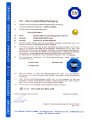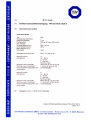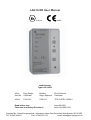
1
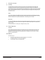
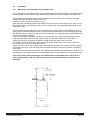
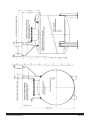
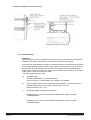
LAG14-ER User Manual ε χ II (1) G 0123 Leak Detector Type LAG 14 ER Afriso Reg. Design Item No. Certificate Building Regs. Approval EX-Conformity Certificate 43410 Z-65.24-1 TPS 03 ATEX 15639 6 70041113 Read before use! Take note of all Safety Directions! Issue 06.2003 Id.No. 854.000.0153 Supplied By: Afriso Eurogauge Ltd., Imberhorne Lane, East Grinstead, West Sussex, RH19 1RF. Tel.: 101342 323641 Fax.: 01342 315 513 email: [email protected] Page LAG14-ER User Manual Table of Contents 1. Safety 3 1.1. 1.2 1.3 1.4 1.5 1.6 1.7 1.8 Dangers inherent in the Equipment Safety directions and hints Design specific application Danger caused by Accessories Emissions Danger Sources Permitted Operators Safety Measures at the Site 3 3 4 4 4 4 5 5 2 Description of Product 6 2.1 2.2 2.3 2.4 2.5 2.6 2.7 2.8 Assembly Range of Application Components, operating and alarm elements Function Types of Operation Technical Data Certificates, Tests, Conformities Examples of Applications 6 6 8 9 9 10 11 11 3 Transport, Installation 12 3.1 3.2 3.3 3.4 3.5 Transport Storage Basic Calculations Installation Supply Connection 12 12 12 14 19 4 Operation 22 4.1 4.2 4.3 4.4 4.5 4.6 4.7 Commissioning Operation Testing Fault Clearance Servicing Maintenance Decommissioning, Disposal 22 23 23 24 24 24 25 5 Appendix 26 5.1 5.2 5.3 5.4 5.5 5.6 Certificate of Engineering Company Spares, Accessories List of leak detection fluids for leak detector Warranty Copyright Certificates 26 26 27 28 28 28 LAG14-ER User Manual Page 2 1. Safety 1.1 Dangers inherent in the Equipment The leak detector LAG 14ER conforms with state of the art technology and the approved safety regulations. Each leak detector undergoes function and safety testing prior to delivery. The leak detector is completely safe if used correctly. The leak detector should be used only if in perfect order and by following the operating instructions. Incorrect operation or misuse may cause danger to: • • • life and limb of the operator the equipment and other property of the owner the functioning of the equipment. All persons involved in the installation, commissioning, operating, servicing and maintenance of the equipment must: • • • be suitably qualified observe these operating instructions implicitly observe the approved safety regulations. It is your safety that is involved! 1.2 Safety directions and hints The following symbols are used in these operating instructions: Danger! warns of impending danger: Non-Compliance with these directions is likely to cause death or severe injuries Warning! points to possible dangerous situations. Non-compliance with these directions may result in death or severe injuries. Caution! points to possible dangerous situations. Non-compliance with these directions may cause minor injuries or damage to property. Important! Hints for the user and other useful information Page 3 LAG14-ER User Manual 1.3 Design specific application The leak detector LAG 14ER is designed exclusively for monitoring double wall tanks specified in paragraph 2.2 with leak detection fluid in the monitoring space during storage above or below ground of: • • flammable liquid in hazard classes A1, A11, A111 and B according to Section 12 of the VbF regulations non-flammable, water contaminating fluids Leaks in the container (tank) are recognised and shown by a lowering of the leak detection fluid level. Not intended for other applications! Unauthorised adaptations and changes of the product lead to considerable safety risks and are not permitted for reasons of safety! Afriso-Euro-Index will not accept any liability for resulting damages or damage caused by non-design specific use. Please note: Under CE requirements we are obliged to draw your attention to the following warnings and safety hints. Warning! Mains voltage (230V, 50Hz) in alarm unit Will cause severe burns, can kill you Do not bring alarm unit into contact with water and disconnect mains before opening up alarm unit Do not carry out manipulations on alarm unit. Important! Adhere strictly to operating servicing and maintenance requirements set out in these operating instructions. 1.4 Danger caused by Accessories Additional equipment for the transmission of the output signal may only be installed by a qualified electrician. 1.5 Emissions The A-rated sound level of the audible alarm must be at least 70 dB (A) at a distance of one metre. 1.6 Danger Sources The leak detector works with mains voltage (230V, 50Hz) Such voltages can cause the severest degree of burns. A person coming into contact with mains voltage can be killed. LAG14-ER User Manual Page 4 Disconnect mains voltage (remove fuses) before opening the alarm unit or prior to servicing and cleaning operations! The LAG 14ER alarm unit just be installed in a non-hazardous, safe area. The probe circuit of the Leak Alarm is certified Intrinsically Safe [EEx ia] IIC by TÜV Germany, Certificate Nr. TPS 03 ATEX 15639 6. Follow installation regulations and relevant Codes of Practice for Intrinsically Safe equipment. The leak detector may only be used: • • for the design-specific application if in a technically safe and perfect condition. Any faults which might affect safety must be remedied instantly! 1.7 Permitted Operators The leak detector may only be installed and commissioned by fully trained personnel. Electrical work should only be carried out by a trained electrician and comply with VDE regulations. Trainee personnel may only work on this product under supervision of an experienced person. The installing technician must make operating instructions available to the operator. The installing technician and the operator must have read and understood the operating instructions before beginning work. The minimum age of the operator is 16 years. 1.8 Safety Measures at the Site The leak alarm unit must be mounted in a clearly visible position on a level, firm and dry wall. The alarm unit must be out of reach of water or water splashes. The leak alarm unit must not be installed in hazardous areas! Important! Ensure with appropriate checks that the leak detecting device and its environment are clean, accessible and visible at all times. Page 5 LAG14-ER User Manual 2. Description of Product 2.1 Assembly The leak detector consists of an alarm unit a probe and a leak detection fluid header tank. The alarm unit and the probe are connected by a two core probe cable, max. length 50m. The probe fits in the top of the leak detection fluid header tank. If a leak occurs in the monitoring space the leak detection fluid level falls in the leak detection fluid header tank and the electrode rods of the probe will be uncovered. The alarm unit senses the changes in the resistance and operates the alarm. Probe The probe consists of two metallic electrode rods which are fixed at a set distance from each other. A 34mm diameter casing encloses the two electrode rods and fixes the probe in the leak detection header tank. The probe is fitted with a 1 metre long, two-core cable. Alarm Unit The LAG 14ER alarm unit contains alarm and operating elements and all electronic components for interpreting and transforming the probe signal into a digital output signal in an impact proof plastic housing. The output signal is a normally open voltage-free relay contact. 2.2. Range of Application Container Only double skinned storage tanks are permitted, which are unpressurised and conform with DIN standards 6608, 6616, 6618 part 3, 6619, 6623 and 6624 or have been issued with an inspection mark that states that the interstitial space is suitable for the connection of a leak detector for liquid systems. Stored Material: Permitted only for • • flammable liquids assigned to hazard classes AI, AII, AIII and B according to Section 12 of the VbF regulations non-flammable, water-incompatible fluids. LAG14-ER User Manual Page 6 Permitted storage systems When using unpressurised containers (tanks) and depending on the container design non-flammable, water-incompatible fluids of the following densities may be stored in the containers (tanks): 1. Container according to DIN 6608 2.5m dia. permissible density 2.9m dia. permissible density 2. Container according to DIN 6616, 76623 and 6624 2.5m dia. permissible density 2.9m dia. permissible density 3. 1.90 g/cm3 1.85 g/cm3 Container according to DIN 6618 part 3 for all design heights permissible density 4. 1.90 g/cm3 1.75 g/cm3 1.0 g/cm3 Container according to DIN 6619 2.60m height permissible density 2.76m height permissible density 2.84m height permissible density 1.90 g/cm3 1.84 g/cm3 1.78 g/cm3 Special conditions Important! The leak detection fluid must not cause a dangerous reaction with the stored material. In other respects the conditions of these operating instructions prevail, especially paragraph 1.3 design specific applications. Page 7 LAG14-ER User Manual 2.3 Components, Operating and Alarm Elements LAG14-ER User Manual Page 8 2.4 Function The leak detector LAG 14ER monitors the interstitial space of double skinned tanks, the space being filled with leak detection fluid. In the event of a leak in the inner or outer skin of the tank, above or below the levels of the stored material or groundwater, leak detection fluid escapes, causing the leak detection fluid level to fall in the header tank. The alarm unit recognises the change in resistance, provides a visual and audible alarm and activates the output relay. Probe The leak detection fluid header tank is mounted above the monitoring space. The underside of the leak detection fluid header tank is linked by a hose to the top side of the monitoring space. Thus the leak detection fluid header tank forms the highest point of the interstitial space. The space is filled with leak detection fluid up to the centre of the leak detection fluid header tank. The probe reaches from the top into the leak detection fluid header tank so that the ends of the electrodes are immersed in the leak detection fluid. Both electrodes are connected to the alarm unit via a two core cable. Alarm Unit The alarm unit provides constant monitoring of the electrical resistance between the two electrodes of the probe. When in operation the green Supply On light is always illuminated. If the probe resistance falls below 5kΩ the alarm unit indicates normal operation: the green light is on, the red Alarm light is off, the relay is open. If the resistance rises above 5kΩ, the alarm unit indicates a leak, the red Alarm light and the audible alarm sounds and the internal relay operates. In the event of an alarm the audible alarm can be silenced by using the mute pushbutton. In the event of mains failure no alarm occurs. When mains voltage is restored again the equipment is immediately operational and any leak that occurred in the meantime will be indicated. The green ‘Supply On’ light comes on as soon as the leak detector is connected to mains supply. The Test pushbutton provides a function check by simulating a leak alarm situation. 2.5 Types of Operation The leak detector LAG 14ER has an integral output relay with voltage-free output contact, which permits the alarm signal to be transmitted to auxilliary equipment. During normal operation the contact is open, in an alarm situation the contact will close. Page 9 LAG14-ER User Manual The leak detector 14ER can be operated with or without auxiliary equipment. Auxiliary equipment that can be used are: optical and audible alarm devices, remote controls, structural process controls, etc. 2.6 Technical Data Probe (probe and housing): Dimensions (W x D x H) Space requirements (W x D x H) Weight Electrode housing Electrode rods Resistance Cable connection - standard length - max. length Probe voltage Tank (conductive) black Surface resistance Capacity, working Total capacity Hose connection Mechanical connection Electrical connection Permitted ambient temperature Protection 300 x 150 x 380m 500 x 200 x 700mm 1.0 kg Plastic 34mm dia. V2A, 3mm dia. Leak detection fluid H05VV-F, 2 x 1mm2 1m 50m (shielded) max. 17V, AC Hostalen or Vestolen < 109 Ohm 4.5 litre 9.7 litre EPDM hose 14 x 3 (LW = IW14) (interior measurement) see paragraph 3.4 see paragraph 3.4 -5°C to + 50°C IP20 DIN 40 050 Alarm unit SE2: Dimensions (L x W x H ) Weight Supply voltage Rated output Appliance fuse Operating delay Intrinsically safe probe circuit Intrinsic safety Addit. connection Breaking capacity of output relay Relay contact fusing Permitted ambient temperature Safety group Safety type EMC Emissions EMC Immunity LAG14-ER User Manual 162 x 97 x 62mm 0.4 kg 230V AC +/- 10%, 50/60 Hz 5VA 32mA Ex none U <16.8V, 1<57mA [EEx ia] IIC 1 output relay (1 make contact) max. 250V, 2A, resistive load 2A -5° to 40°C II DIN 57 700 IP 30 DIN 40 050 acc. to EN 50081-1 acc. to EN 50082-2 Page 10 2.7 Certificates, Tests, Conformities The leak detector LAG 14ER has the design certificate 70041113 and has been approved under Building Inspectorate Certificate No. Z-65.24-1 and has passed the test for electrical equipment for hazardous areas and obtained the TÜV Germany, Certificate of conformity Nr. TPS 03 ATEX 15639 6. The leak detector LAG 14ER conforms with EMV Guidelines (89/336/EWG/ and 92/31/EWG) for low voltage guideline (73/23/EWG and 93/68/EWG) and EX framework guideline (76/117/EWG) * (* EWG = EEC) Page 11 2.8 Examples of Applications 1. Standard application: LAG14-ER User Manual 3. Transport, Installation 3.1 Transport The alarm unit, the probe and the leak detection fluid header tank are supplied together with these operating instructions, shrink-wrapped in PE-foil. The external dimensions are 380 x 380 x 150mm. The weight is 1.5kg. Do not throw or drop. The leak detector LAG 14ER may be damaged or scratched. Protect from wet, damp, dirt and dust. 3.2 Storage The leak detector LAG 14ER can be stored in a dry room and wrapped in this foil at temperatures ranging from -10°C to + 60°C. Protect from wet, damp, dirt and dust. 3.3. Basic Calculations 3.3.1 LAG 14ER fitted to tanks below ground (min. 30 cm covering) The active content of the leak detection fluid header tank is limited by the filler height screw in the centre of the tank and amounts to 4.5 litre. Below ground storage tanks require 1 litre leak detection fluid in the leak detection fluid header tanks per 100 litre capacity in the interstitial space. The leak detection fluid header tank is sufficient for a 450 litre capacity interstitial space. This equals storage containers with a storage capacity of up to 60,000 litres. The leak detector LAG 14ER can, together with additional header tanks of 4.5 litre active contents each, also be used for storage tanks with a larger interstitial space capacity. The additional header tanks must be connected up together and with the leak detection fluid header tanks by means of EPDM flexible hose. Amount of leak detection fluid in interstitial space of double skin tank. According to rating plate. 0 450 900 1350 1800 - 450 900 1350 1800 2250 LAG14-ER User Manual No. of leak detecting fluid header tanks (with probe) No. of additional tanks required (without probe) 1 1 1 1 1 0 1 2 3 4 Page 12 3.3.2 LAG 14ER with above ground containers/tanks (covering less than 30 cm) Above ground storage containers require 1 litre leak detection fluid in the leak detection fluid header tanks per 35 litre monitoring space capacity. One leak detection fluid header tank is sufficient for 157.5 litre capacity monitoring space. This is equal to storage containers with a capacity of up to 20,000 litres. The leak detector LAG 14ER can, together with additional header tanks of 4.5 litre active contents each, also be used for storage containers with a larger monitoring space capacity. The additional header tanks must be connected up together and with the leak detection fluid header tanks by means of EPDM-pipes. Amount of leak detection fluid in monitoring space of containers containers according to rating plate of container 0 -157.5 157.5 -315 315 - 472.5 472.5 - 630 630 - 787.5 Page 13 No. of required leak detecting No. of required additional fluid header tanks with probe: (without probe) 1 1 1 1 1 0 1 2 3 4 LAG14-ER User Manual 3.4 Installation 3.4.1 Mounting of the leak detection fluid header tanks Prior to installation the required amount of leak detection fluid must be ascertained on the rating plate of the storage tank and the number of leak detection fluid header tanks (see paragraph 3.3) determined. The leak detection fluid header tank can be installed directly at the alarm unit or near the monitored storage tank in Ex-hazardous areas to EEx ia IIC. (Observe Codes of Practice in relevant country). When fitting the leak detection fluid header tank in the Ex-area, the access shaft or in the open, ensure that neither surface or precipitation water nor dirt or drifting sand can penetrate the header tank or the cable junction box. The leak detection fluid header tank must be mounted high enough above the interstitial space for the static pressure of the leak detection fluid on all parts of the interstitial space to be sufficient to cause the leak detection fluid to escape in a leak situation and the fluid level in the leak detection fluid header tank to fall until the alarm is triggered. The minimum distance between the crown of the tank and the lower edge of the leak detection fluid header tank generally depends on the specific gravity of the stored material and, in the case of underground tanks, on possible groundwater or water levels above the crown of the tank. For storage containers below ground the leak detection fluid header tank must be mounted at least 30 cm above the crown of the storage container. Where the tested system over pressure of the interstitial space of the tank is 0.6 bar, the leak detection fluid header tanks may not be set higher than 5.5m above the base of the tank (in relation to the filling level screw). The minimum distance between the tank crown and the leak detection fluid header tank in relation to the specific gravity of the stored material can be ascertained from the three diagrams on the following page. To prevent a static charge building up in the leak detection fluid header tank in the Ex-area, it must be well earthed. This anti-static earth wire must be insulated and have a diameter of at least 4mm2. LAG14-ER User Manual Page 14 MINIMUM DISTANCE BETWEEN CONTAINER TOP AND LEAK DETECTION FLUID HEADER TANK IN RELATION TO DENSITY OF STORED MATERIAL Container: DIN 6608 Min. distance a min (cm) Example DIN 6608 D 25 x 2000 Q = 1.75 a min = 180 cm Density Q (g/cm3) Container - Diameter ≤ 2.5 m permitted density ≤ 1.9 ≤ 2.9 m permitted density ≤ 1.75 Container: DIN 6616, 6623 and 6624 see previous example Min. distance a min (cm) Example: DIN 6618 DA 60 x 2500 Q = 1.7 a min = 175cm Density Q (g/cm3) a min = D(Q-1) + 30 (cm) a max = 550-c-D (cm) Container- Diameter ≤ 2.5m permitted density ≤ 1.9 ≤ 2.9m permitted density ≤ 1.85 Container: DIN 6619 non-pressurised operation Ground and banked up water below container top. Min Distance etc. as previous example Min. Distance a min (cm) Example: DIN 6619 D7 x 2.6m Q = 1.65 a min = 200 cm Density Q (g/cm3) Container height ≤ 2.6m permitted density ≤ 1.9 ≤ 2.76m permitted density ≤ 1.84 ≤ 2.84m permitted density ≤ 1.78 Page 15 LAG14-ER User Manual LAG14-ER User Manual Page 16 Installation example for correct earthing 3.4.2. Pipe Installation Important! Piping and fittings must not be galvanised internally as zinc reacts with the permitted leak detection fluids which may lead to an accumulation of deposits and clogging. The connection pipes between storage tank and leak detection fluid header tank must have an even fall towards the tank and must not be capable of being turned off. All connections must be tight. Pipes and fittings must not be the sole support of the leak detection fluid header tanks. This must be fixed to a nearby wall, in an instrument housing or on a stand made of flat or angle iron at the dome shaft. The following piping may be used: a) 3/4" Steel Pipes. Surface coated outside, not galvanised inside. Same for Fittings. If used underground, insulate on the outside. b) Copper or Brass tubes factory-coated with plastic insulation, to be mounted with a separate insulating piece at the tank connection. Min. ID13 mm. Recommendation 15 x 1 mm. c) Only BAM certified hose pipes are permitted. EPDM-hose 14 x 3 (IW 14) in the AFRISO Assembly kit is approved under 3.12/BAM/2090/84 EPDM-hose 14 x 3 (IW 14) in the AFRISO Assembly kit is approved under 3.12/BAM/2090/84 Page 17 LAG14-ER User Manual Example of LAG Pipe Installation 3.4.3. Fitting of the Test Valve The LAG-Assembly Kit contains a test valve with 1" female thread and a hose connection piece for 12x2 mm hoses and all small items (AN 40540) required for connecting the leak detector. The test valve must be fitted to the connector point opposite the leak detector. The test valve must be fitted at least 100mm below the lower edge of the LAG-fluid container on the storage container. A free space is required below the test valve for a moveable collection container to catch the leak detection fluid escaping during function checks. During function checks leak detection fluid must escape from the test valve at the rate of approx. 0.5litres/min. LAG14-ER User Manual Page 18 3.4.4. Mounting the Alarm Unit Important! The alarm unit of the leak detector LAG 14ER must be mounted at eye level on an even, firm and dry wall. The alarm unit of the leak detector must be accessible and visible at all times. Select a site where the ambient temperature does not exceed - 5°C to + 40°C. If mounted in the open air, the alarm unit must be protected from direct weather influence. The alarm unit of the leak detector LAG 14 ER must not be mounted in a hazardous area. The leak detector may only be mounted and commissioned by qualified specialist personnel. To install the alarm unit undo the two Phillips screws at the front of the alarm unit and lift off the housing cover. The alarm and service elements of the housing cover are connected by a flat ribbon cable and plug strip to the printed circuit board. The plugstrip can be set vertically to the pc board. Fix the lower part of the housing with two fixing screws (mounting holes provided at top right and bottom left) to the wall. Electric connection to be carried out as per paragraph 3.5. Connect flat ribbon cables of the housing cover with the plug strip of the pc board. Do not twist the flat ribbon cable! Replace the housing cover and fix with the two Phillips screws. 3.5 Mains Connection Caution! Mains Voltage (230V, 50 Hz) Causes severe burns, can kill you. Electrical work must only be carried out by a qualified electrician. Install only when power is disconnected! Important! Follow IEE - Regulations, accident prevention rules and the operating instructions for the leak detector and tank installation requirements! Connect the LAG 14ER Alarm unit to a separate unswitched 230V supply! Page 19 LAG14-ER User Manual Wiring Diagram Mains Supply The LAG 14ER unit must be supplied via an unswitched fuse unit to prevent un-authorised isolation of the system. Feed the supply cable through the right hand cable entry into the alarm unit. Connect the live phase to the terminal L1, the neutral to terminal N and earth to terminal PE. The line to the alarm unit must be fused (13A). Probe If the alarm unit and the leak detection fluid header tank are installed next to each other, the probe cable can be connected directly to the alarm unit. Ensure that the probe can be removed easily from the header tank for routine maintenance checks. Do not shorten the probe cable. LAG14-ER User Manual Page 20 For increased distances install an IP 65 rated junction box permanently above and next to the leak detection fluid header tank. Ensure that the probe can be removed easily from the header tank for routine maintenance checks. To extend the probe cable use 2 x 1mm2 cable with blue outer sheathing suitable for intrinsically safe circuits. If the length exceeds 5 metres use screened cable. The total length of the cable must not exceed 50 metres. If cables are run in conduit or underground ducts 2 x 1.5mm2 must be used. Intrinsically safe and non-intrinsically safe circuits must not be run in the same conduit. Follow IEE regulations. Run probe cable separate from mains power cables. Provide the probe cable with adequate protection against damage. Pass the probe cable through the left hand cable entry of the LAG 14ER unit and connect accordingly to wiring diagram (page 20) Output The output of the leak detector consists of a voltage free relay contact. The relay closes when an alarm condition is reached. The relay contact is fused with an internal 2A fuse. IMPORTANT Voltage surges occur when inductive equipment is switched off. The functioning of electrical appliances may considerably affected and the switching contact destroyed. Inductive equipment must therefore be wired with RC combinations, e.g. 0.1µF/100ohm, common to the trade. Page 21 LAG14-ER User Manual 4. Operation 4.1. Commissioning Before commissioning check by using the following checklist that all conditions for a trouble free operation are met. Conditions Met Not Met Has number of header tanks been established? Have header tanks been installed according to 3.4.1. ? Have pipes been installed according to 3.4.2 ? Has test valve been installed according to 3.4.3 ? Has alarm unit been installed according to 3.4.4. ? Has electric connection been made according to 3.5 ? Has supply connection been made ? Is probe connected to alarm unit ? Is output relay wired (if required) ? Has flat ribbon cable been connected to pc board ? Has alarm unit housing been screwed down again ? When all conditions have been met, the leak detection fluid can be topped up: Filling Double walled containers/tanks are charged with leak detection fluid in the interstitial space. The leak detection fluid quantity must be ascertained and shown on the container rating plate. Only top up with listed leak detection fluid mixed with water at the prescribed ratio unless a BAM certificate states that the intended leak detection fluid can be moved with the leak detection fluid in the interstitial space. To commission, open the test valve, place a suitable container below the valve, and remove the probe from the leak detection fluid header tank. Remove the fill level screw from the leak detection fluid header tank and start filling. Do not close the test valve until leak detection fluid emerges from the valve. Continue filling with leak detection fluid until the overflow opening at the filling level mark is reached. Refit the fill level screw and insert probe. The 5mm diameter aeration opening at the neck connector of the leak detection fluid header tank must remain open! The unit is now ready for operation. Switch on electric supply with own mains fuse. The green operating light will come on. The specialist firm must enter installation, commissioning and testing details of the leak detector on the form given in paragraph 5.1. LAG14-ER User Manual Page 22 4.2. Operation The leak detector monitors double skin storage tanks. When a leak occurs, leak detection fluid runs out and the leak detector activates the alarm. Operating the leak detector is therefore limited to its regular monitoring. + + + green operating light on? red alarm light off? sound alarm off? OK OK OK When pressing the Test pushbutton or withdrawing the probe from the leak detection fluid header tank the red alarm light must light up and the audible alarm sound. Carry out this test at weekly intervals. In the event of an alarm: In the event of an alarm top up the leak detection fluid, mixed with water in the prescribed ration, up to the marked filling height. If the alarm is repeated a leak has occurred. The audible alarm can be silenced by pressing the Mute pushbutton. The red alarm light continues to be lit. Inform the installation specialist immediately. 4.3. Testing - by simulation To guarantee safe functioning carry out a function check at least once a year by simulating a real alarm situation. Open the test valve and catch the emerging leak detection fluid in a suitable container. The leak detection fluid must emerge at a rate of approx. 0.5 litres/min. As soon as the leak detection fluid header tank has emptied a visual and audible alarm should operate. Close the test valve and return the drained fluid to the header tank. The visual and audible alarm signals should cancel automatically. - at the probe: Once a year and after each and every service or repair carry out the following test: Remove the probe from the leak detection fluid header tank. The red alarm light must light up and the audible alarm sound. Re-insert the probe. The visual and audible alarm signals should cancel automatically. -at the alarm unit: Correct functioning of the leak detector can be checked at any time by operating the Test pushbutton. When pressing the Test pushbutton, the connection to the probe is interrupted. The red alarm light must light up and the audible alarm must sound. Page 23 LAG14-ER User Manual 4.4. Fault Finding: Fault Remedy Green operating light is off Check supply voltage! Check fuse! Has flat ribbon cable been connected to PC board? Red alarm light is on Is there a leak? Top up leak detection fluid! Is probe connected? Is there a line interruption in the probe cable? Red alarm light is on continuously even if probe is immersed in leak detection fluid: Line interruption in the probe cable? Line interruption in the probe? Line interruption in the alarm unit? Activating the Test pushbutton does not produce results: Change the alarm unit! Removing the probe from header tank does not give alarm: Short in the probe? Short in the probe cable? Short in the alarm unit? 4.5 Servicing The functioning of the leak detector must be tested once a year by simulating an alarm situation. Ensure with suitable tests that the leak detector and its environment are clean, accessible and visible at all times. Other than that the leak detector requires no maintenance. It is recommended to take out a service agreement with a specialist firm listed in TRbF 180 and/or 280. 4.6. Maintenance Warning! Leak detectors are safety devices and faults can only be repaired by the manufacturer. Interference with, or modification of, the product causes considerable safety risks! LAG14-ER User Manual Page 24 WARNING! Mains voltage (230V, 50 Hz) Causes severe burns, can kill you. Electrical work must be carried out by a qualified electrician. Switch off current before installing! In situ repairs must be carried out by a qualified electrician while current is switched off. The current must be safety disconnected during repairs. Exchanging mains fuse F1: Switch off mains power Remove housing cover Remove transparent cover from fuse Change fuse F1: M32mAEx Snap on transparent cover over fuse Connect flat ribbon cable with plug strip Replace housing cover and screw tight Switch on mains power Changing the relay fuse F2: Switch off mains power Remove housing cover Open black vertical fuse holder with a screw drive (1/4 turn anti-clockwise) and remove insert. Replace fuse F2: M 2A Plug insert with replaced fuse into fuse holder and lock in place with a 1/4 turn clockwise Connect flat ribbon cable with plug strip Replace housing cover and screw tight Switch on mains power. 4.7 Decommissioning, Disposal Switch off mains power for decommissioning. For disposal detach the housing parts of the alarm unit from the PC board and dispose of according to local regulations (e.g. recycling yards) sorted into the appropriate grades. Page 25 LAG14-ER User Manual 5. Appendix 5.1 Certificate of Engineering Company (under TRbF 180 and/or 280) I herewith confirm installation of the leak detector together with the function check of the leak detection device in accordance with operating instructions for ……….. tank according to or in line with DIN 66 ………………… Serial No. …………………… Capacity in litres …………… Leak detection fluid: Reference: …………………… Quantity in litres: ……………. in the monitoring space. User and address of plant Engineering Firm: ……………………………… ……………………………….. ……………………………… ……………………………….. 5.2. Spares, accessories LAG 14ER alarm unit LAG container, black LAG probe LAG assembly kit LAG assembly kit (add.cont.) Hose nipple 3/4" (LAG-cont.) Hose connector piece 1" Test valve 1" EPDM-hose 14 x 3mm Leak detection fluid concentrate Cable extension fitting Mounting frame for alarm unit Event reporting device AM1 Event reporting device AM2 RC combination 0.1µF/100A Mains fuse F1 (M 32mA Ex) Relay fuse F2 (M 2A) LAG14-ER User Manual Item No. 40642 40731 40510 40540 40542 40558 40557 40560 40543 43645 40041 43520 90001 90002 Id. No. 608 001 5100 941571 0032 941571 2000 Page 26 5.3 List of Leak Detection Fluids for Leak Detector The leak detection fluids listed, have been tested in accordance with the building and testing principles for leak detectors for containers and pipes TRbF 501 and 502 by the Federal Department for Material Research and Testing (BAM) and may be used for leak detectors for fluid systems. They have been tested for their fungicidal effect and their compatibility with combustible fluids; heating oil EL, diesel fuel and petrol fuels. No other leak detection fluids can now be used in interstitial spaces in double skin tanks. The leak detector LAG 14ER is suitable for use with all the leak detection fluids mentioned below. The following leak detection fluids may be mixed together for the purpose of filling or topping up of the leak detection fluid header tanks: Hoechst AG “Antifrogen N” “Leak Detection Fluid Hoechst” and the following can be mixed with each other: German Avia “Avilub-Leak Detection Fluid” Metasco “Fauch 950 Leak Detection Fluid” BASF “Glymin” Leak Detection Fluid BAM test ref. 1.3/9790-5.1/3436 with BAM test ref. 1.3/10723/5.1/3833 BAM test ref. 1.3/11477-N1-5.14372-N1 BAM test ref. 1.3/11477-N2-5.1/4372-N2 BAM test ref. 1.3/11477-5.1/4372 Other leak detection fluids may not be mixed with each other! Company Hoeschst AG 8261 Gendorf Dow Chemical Europe CH-8810 Horgen Chem Werke Hüls 4370 Marl Gunter Schröder 2100 Hamburg 90 Deutsche Pentosin W. 2000 Wedel Deutsche Shell 6000 Frankfurt Wilhelm E.H. Biesterfeld 2100 Hamburg 90 BASF Ludwigshafen Chemische Industrielle GmbH 2000 Hamburg 1 Dow Chemical Europe CH-8810 Horgen Deutsche Avia Mineralöl GmbH 8000 Munich 80 Metasco Chem. Techn. Prod. 6200 Wiesbaden Page 27 Type Antifrogen N Leak detection fluid Hoescht DOWCAL 20 Leak detection fluid ILEXAN -Leak detection fluid concentrate WBC 961 Leak detection fluid Pentosin-Indikol-Concentrate Glycoshell 1 Leak detection fluid WBC 962 Leak detection fluid Glymin Leak detection fluid KOREX TB 86 IV Leak detection fluid DOWCAL 10 Leak detection fluid AVILUB Leak detection fluid FAUCH 950 Leak detection fluid BA Test Ref 1.3/9790 - 5.1/3436 1.3/10723 - 5.1/3833 1.3/9577 - 5.1.3371 1.3/9829 - 5.1/3465 1.3/8981 - 5.1/3347 1.3/8758 - 5.1/3398 1.3/4281 - 5.1/3457 1.3/11805 - 5.1/4836 1.3/11477 - 5.1/4372 1.3/11622 - 5.1/4570 1.3/11621 - 5.1/4543 1.3/11477-N1-5.1/4372-N1 1.3/11477-N2-5.1/4372-N2 LAG14-ER User Manual 5.4 Warranty The manufacturers, Afriso-Euro-Index GmbH warrant this appliance for 6 months from the date of purchase. During this warranty period we will correct all material or manufacturing faults free of charge either by repairing or replacing the appliance as we deem fit. This warranty does not cover: damage caused through inappropriate use, normal wear and tear only marginally affecting the value or the performance capability. Work by unauthorised persons or the use of other than the original AFRISO spares render the warranty invalid. Claims will be valid in all countries where these appliances are sold by Afriso-Euro-Index or their authorised dealers. 5.5. Copyright The copyright for these operating instructions remains the property of Afriso-Euro-Index gmbH. Reprinting, translating and copying, even in the form of extracts require written permission. We reserve the right to alter technical specifications shown in text or illustrations of the operating instructions. 5.6 Certificates continued on the following three pages. LAG14-ER User Manual Page 28