1
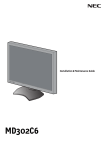
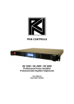
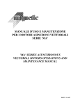
PKN AUDIO
PKN 3PHASE-20K / PKN 3PHASE-40K
User Manual
All PKN AUDIO products designed and made in HUNGARY / EUROPEAN
UNION
Index of Contents
1. Technical Specifications
2. Safety Instructions
3. AC Powering
1. Three phase operation
2. Single phase operation
4. Front panel / back panel
1. Front panel
2. Rear panel
5. Display
1. PKN 3PHASE-20K display
2. PKN 3PHASE-40K display
6. Menu system
6.1 Turn ON / OFF device
6.2 The INPUT settings
6.3 Gain settings
6.4 Bridged mode
6.5 Limiter settings
6.6 AC Power limiter
6.7.1 Language settings
6.7.2 LCD display
6.7.3 LED bars
6.7.4 Network settings
6.7.5 Remote mode
6.7.6 Service
6.7.7 Power-ON sequence
6.7.8 Protections
6.7.9 Cooling
6.8 User Profiles
6.9 Device information
7. Input signal connectors
7.2 Output power connections
1. Technical Specifications
Parameter
Channel number
Output Power 8 Ohms
PKN 3PHASE-40K
PKN 3PHASE-20K
4 input/ 4 output
2 input/ 2 output
4 x 4000W
2 x 4000W
Output Power 4 Ohms
4 x 7500W
2 x 7500W
Output Power 2.6 Ohms
4 x 10000W
2 x 10000W
Bridged Output Power 8 Ohms
2 x 8000W
1 x 8000W
Bridged Output Power 4 Ohms
2 x 15000W
1 x 15000W
Bridged Output Power 2.6 Ohms
2 x 20000W
1 x 20000W
Peak Output Voltage per Channel
256V (181Vrms)
Peak Output Current per Channel
130A
Power Supply
Dual, Two independent High Frequency Resonant Switching with active Power Factor Correction
Typical Power Factor
>0.92 above 2000W
AC Power input in Three Phase mode
3x 400V (25A**) no Neutral connection needed
AC Power input in Single Phase mode
Operational AC Voltage range in Three Phase mode
Operational AC Voltage range in Single Phase mode
230V (63A**)
3X 208V- 3X480V 45...65Hz Still operational in case of single phase loss
90V- 275V** 45...65Hz 400Vac proof in single-phase mode
Maximum AC line current draw in Three Phase mode
3X 32A (Separated AC Power limiter for AB and CD
Channels)
3 x 16A
Maximum AC line current draw in Single Phase mode
80A
40A
Inrush current limiting
Yes, very soft turn-on with programmable turn-on sequencer for larger systems
Minimum Operational AC input
AC Overvoltage Proof
65V (Single Phase mode)
1.5 KV in Three Phase mode, 0.75 KV in Single Phase mode
Signal to Noise ratio (with “A-weighed” filter)
112dB
Frequency response (+/- 0,05dB)
20Hz – 30KHz
Frequency response (+/- 3dB)
5Hz - 60Khz (High Frequency filter off)
Damping factor (20-100Hz, 8R****)
>12000
Damping factor (1KHz, 8R****)
>6500
THD + IMD (20Hz - 20kHz full power)
0.15% max (typical <0.05%)
Output Slew Rate
100V/us (Input and HF filters bypassed)
Crosstalk (A <-> B), (C <-> D)
Crosstalk (AB <-> CD)
Output protections
Input sensitivity (analog inputs)
>75dB
>106dB
CCM (0 Ohm STABLE), Overload, Short circuit, HF, unmatched loads, DC fault, lost connection, Programmable
limiters
0.775Vrms or 2Vrms (configurable from the menu)
Input impedance
Output connectors
Input connectors
10K+10K, Balanced
4X NEUTRIK NLT4M*
2X NEUTRIK NLT4M*
4X NEUTRIK XLR
2X NEUTRIK XLR
Networking
Standard Ethernet
Built-in DSP
Size
Limiter
Optional
1RU, 455mm depth
Output Voltage (1V/step), Sustained Output Power Limiter (10W/step)
Latency from the analog inputs
Weight
Operational temperature range
Cooling
1RU, 385mm depth
< 0.025 ms
13,7 Kgs
8 Kgs
0C - +45C
Forced air cooling with hidden high-performance FANS , Front to rear airflow
** There is a possibility of multiple line-current limiting methods from the menu booth in three and single phase mode
*** Please note that best performance is around 3X400V or 230V operation, bellow 208V the sustained output power performance drops
**** Measured directly on the output points with special connections, output connector excluded from the measurement circuit
Specifications are subject to change without prior notice
2. Safety Instructions
This device is a very high power professional amplifier indented only for real professional use. Operation and set-up shall
be made only by well-trained personnel who understands the risks and potential hazards of the device. Non proper installation or setup of this amplifier due its power capabilities and unusual high-voltage operation may causes serious risk of fire or potentially lethal
electric hazard.
Warning Signs applied on the device and their meanings
CAUTION! RISK OF ELECTRIC SHOCK.
NOT OPEN! THE DEVICE MAY
DANGER DO
STORES DANGEROUS ENERGY EVEN
HIGH VOLTAGE LONG PERIODS AFTER TURNED OFF.
CAUTION! TO PREVENT ELECTRIC SHOCK DO NOT
REMOVE TOP COVER. THERE ARE NO USER
SERVICEABLE PARTS INSIDE! REFER SERVICING TO
QUALIFIED SERVICE PERSONNEL. SERVICING IS
REQUIRED WHEN THE DEVICE HAS BEEN DAMAGED IN ANY WAY.
INSIDE
DO NOT OPEN
The lightning bolt triangle is used to alert the users to the risk of electric shock. The exclamation point triangle is used to alert the
users to important operating or maintenance instructions.
WARNING: TO REDUCE THE RISK OF ELECTRIC SHOCK OR FIRE, DO NOT
EXPOSE THIS DEVICE TO RAIN OR MOISTURE!
THIS DEVICE MUST BE GROUNDED
Always ensure proper protection earth (PE) connection prior use. Do not use
or turn on the device if there any sign of AC power cable or ground
connection interrupted or cable/connectors cracked.
BADLY ESTABLISHED OR MISSING GROUND (PE) CONNECTION
COULD MAKE SERIOUS RISK OF ELECTRIC HAZARD.
NEVER DISCONNECT POWER CABLE UNDER LOAD OR WHEN THE AMPLIFIER IS TURNED ON.
ALWAYS TURN OFF (GO STADBY MODE) PRIOR DISCONNECT AC LINE CONNECTOR.
INDOOR USE ONLY
This equipment needs solid rack-mounted installation for safe and reliable operation. Use rear rack
mounting supports every time when the amplifier(s) moved or for mobile racks.
Install the amplifier in a well ventilated location where it will not be exposed to high temperature or
excessive levels of humidity. Do not install the amplifier in a location that is exposed to direct rays of
the sun, or near to hot appliance or radiators.
Do not exceed the operational temperature range of the device. If necessary to ensure safe operation
add extra active cooling for the rack chambers or rooms where the equipment operated.
CAUTION! HIGH MAGNETIC FIELDS!
DO NOT locate sensitive highgain equipment such as pre-amplifiers, DSPs, EQ, tape decks directly above or bellow the unit.
This power amplifier has a high power density, it may has a strong magnetic field which can induce hum into unshielded or weak
protected sensitive low-signal devices that are located nearby. The field is strongest just above and below the unit.
If an equipment rack is used, we recommend locating the amplifiers in the bottom of the rack and the sensitive equipments at the top.
SPEAKER OUTPUT SHOCK HAZARD!
These very high power amplifiers are capable of producing hazardous output voltages. To avoid
electrical shock, do no touch any exposed speaker wiring while the amplifiers are operating.
The operational power level requires proper cross-section area wiring with class-III type insulation
capabilities. Bad or undersized cabling would not only affects sound quality but could easily make
fire or electric shock hazard. We recommend to use so called “High voltage AC insulation tester” for
checking the insulation strength of output cables and connectors at least with 500Vac (50Hz).
Always connect every inputs, outputs properly to the amplifiers prior turned on. Never disconnect
output connections or signal inputs under load or when the device turned on.
If you have any questions, contact your PKNC dealer, or send an email: [email protected]
3. AC Powering
There are two possible ways of AC powering the PKN 3PHASE series . Please note that the best performance delivered
when the amplifier powered by three-phase 400Vac line if the device heavily loaded and pushed close to its maximum power
boundaries.
Two different type of AC cable sets are supplied for each 3PHASE amplifiers, type1 AC cable set is a three phase while type2 cable
set is the single phase power cord. The amplifier automatically sets the operational mode by itself once the AC line(s) applied.
1. Three phase powering mode ( 3x 208Vac – 460Vac )
In the true three phase operational mode the device needs L1, L2, L3 line conductors and protection earth (PE)
conductor for safety reasons. No NEUTRAL connection needed, but proper grounding is essential.
CAUTION. DO NOT CONNECT NEUTRAL CONDUCTOR IN THREE-PHASE
CONFIGURATION. THIS DEVICE MUST BE GROUNDED
Pin label Wire markings Wire color coding Required min. wire size Conductor
connector ( wire label )
40K / 20K
A
NC*
--
--
--
B
PE
Green-Yellow
6mm^2 / 4mm^2
Protection Earth
C
L1
Black
4mm^2 / 2.5mm^2
Line 1
D
L2
Black
4mm^2 / 2.5mm^2
Line2
E
L3
Black
4mm^2 / 2.5mm^2
Line 3
SHELL
Permanently connected to PE
* NC = Not connected
The sequence of line phases are insignificant. The device balances the load perfect symmetrically between phase
conductors by itself automatically. In case of one phase line lost the amplifier remain operational with two phases but
sustained
output power performance may affected while peak power capability maintained.
2. Single phase powering mode ( 90Vac – 275Vac )
For maximum flexibility there is a possibility of single phase AC powering of the device. Please note that the
device needs high current source for proper operation, much higher than operated in three phase mode. Higher AC line current needs
heavy and higher copper cross-sectional area cabling than three phase mode.
CAUTION. THIS DEVICE MUST BE GROUNDED
Pin label Wire markings Wire color coding Required min. wire size Conductor
connector (wire label )
40K / 20K
A
NEUTRAL
Blue
10mm^2 / 6mm^2
Neutral
B
PE
Green-Yellow
10mm^2 / 6mm^2
Protection Earth
L
Black
10mm^2 / 6mm^2
Line*
C
D
E
SHELL
Permanently connected to PE
* C, D, E pins connected together for multiple current handling capability
4. Front panel / Back panel
4.1 The front panel
PKN 3PHASE-20K
PKN 3PHASE-40K
1.
Left side front rack mounting*
2.
Left side handler
3.
AB channel cooling air inlets**
4.
Channel A control jog wheel
5.
--
6.
7.
Channel B control jog wheel
Channel A combined LED bar display
--
Channel B combined LED bar display
8.
Main LCD display
9.
--
Channel C combined LED bar display
10.
Channel B combined LED bar display
Channel D combined LED bar display
11.
Channel B control jog wheel
Channel C control jog wheel
12.
--
Channel D control jog wheel
13.
Power supply cooling air inlets
CD channels cooling air inlets
14.
Right side handler
15.
Right side front rack mounting
* Please check carefully the mounting instructions in section XXX
** CAUTION! Never cover the cooling air slots and take care of free air ventilation in the rack chamber otherwise the heat protection maybe
activated
4.2 The back panel
PKN 3PHASE-20K
PKN 3PHASE-40K
1.
Left side rear mounting flange
2.
ETHERNET connection
3.
Output A
4.
Input A
5.
Cooling air exhaust
6.
Input B
7.
Output B
8.
AC Input connector
9.
--
10.
--
Input C
11.
--
Input D
12.
–
Output D
13.
Output C
Right side mounting flange
5. Display
5.1 PKN 3PHASE-20K main screen
1. Type / Device name information displayed alternating
2. Internal heatsink hotspot temperature
3. Warnings displayed (If any of protections activated)
4. Line 1 Actual AC Voltage
5. Line 2 Actual AC Voltage
6. Line 3 Actual AC Voltage
7. Reserved area for notifications of NET/AVB interface
8. Channel A Gain control settings
modified)
9. Channel A Peak Voltage limiter setting
10. Channel A Input sensitivity
11. Channel A actual output Voltage bar display
12. Channel marker (flashes when c+hannel parameters are modified)
13. Channel A actual loading impedance
14. Channel A measured peak output Voltage
15. Channel A measured peak output Current
16. Reserved notifications area for Channel A DSP
17. Channel A Automatic Gain Reduction is activated
18. Channel B Gain control settings
19. Channel B Peak Voltage limiter settings
20. Channel B Input sensitivity
21. Channel B actual output Voltage bar display
22. Channel marker (flashes when channel parameters
23. Channel B actual loading impedance
24. Channel B measured peak output Voltage
25. Channel B measured peak output Current
26. Reserved notifications area for Channel B DSP
27. NET icon displays active ETHERNET connection
5.2 PKN 3PHASE-40K main screen
1. Type / Device name information displayed alternating
2. A-B Internal heatsink hotspot temperature
3. Warnings displayed (If any of protections activated)
4. Line 1 Actual AC Voltage
5. Line 2 Actual AC Voltage
6. Line 3 Actual AC Voltage
7. C-D Internal heatsink hotspot temperature
8. Reserved area for notifications of NET/AVB interface
9. NET icon displays active ETHERNET connection
19. Automatic Gain Reduction is activated
10. Gain control setting of actual channel
11. Peak Voltage limiter setting of actual channel
12. Input Gain setting
13. Output Voltage bar display
14. Output loading impedance
15. Channel identifier
16. Peak output Voltage measured
17. Peak output Current measured
18. Scrolling notifications area for optional DSP module
6. Menu system
You can go to the menu by long pressing any of the jog buttons on the front panel
M ENU 1. ON / STANDBY
2. Input
1. Signal s ource
1. A
2. B
3. C
Analog / digital
4. D
2. Se ns itivity
1. A
2. B
3. C
-99dB .. +6dB
4. D
3. Grouping inputs
4. M ute channe ls
1. M ute ALL
2. M ute s pe cific channe l
3. Gain
1. A
2. B
-99dB .. 0dB
3. C
4. D
4. Bridge
1. A+B
2. C+D
5. Lim ite r s e ttings
1. A
2. B
U_pe ak , U_ave rage ( t ) P_pe ak P(AES) @Z
3. C
4. D
6. AC pow e r lim iter
1. A+B
Fus ing type & ratings
2. C+D
7. Control pane l
English / Germ an / M agyar
1. Language se ttings
2. LCD Dis play
1. Display contras t
2. LCD Brightne ss
3. Ke ep alive tim e
3. LED bars
1. LED Brightne s s
2. Displaying m ode
IP addre s s
4. Ne tw ork s ettings
Subnet m as k
Gate w ay
M AC addres s
Dis able d / Enabled / Auto
5. Ne tw ork (re m ote) m ode
6. Se rvice
1. Vie w s ervice param e te rs
2. Re se t device
3. Te m pe rature calibration
4. Factory s e t
7. Pow e r on se que nce
Se rvice pass w ord IS re quire d to e nte r
Pow e r on de lay
Ne tw ork w ak e -up
8. Prote ction
Stop / Autos tart
9. Cooling
Sile nt m ode / m ax. perform ance
8. Us e r profiles
1. [ 1,2,3,4,5... ]
9. De vice inform ation
1. Vie w de vice inform ation
Se rial num be r, Work ing hours , His tory
2. Se t device nam e
3. Se t device group
4. Lock de vice
10. Exit to m ain s cree n
* C and D channels are only valid in 3PHASE-40K
6.1 Turn ON / OFF device
Connect your power cord safely and then push one of the front panel jog buttons for a half second and the following display
will appear. Here you can turn ON the device by selecting [ON] button or choose sleep mode by the [OFF]. The device will
remember your selection and if the AC power disappear causing turn off the amplifier will turn ON automatically once the AC line
restored. You can turn-OFF the device by long pressing (>1s) any of jog wheels, going to menu and choose the first 1.
ON/STANDBY. CAUTION! Always connect or disconnect any connectors while the device turned off, never disconnect any wires
under load or when the amplifier is operational.
Once the device gets power and turned ON the main information screen will display actual (measured) AC Voltage values on the
middle top part of the screen. When three phases connected the following information bubbles will appear with the measured values
of line Voltages:
If the single phase power cord connected the following single information bubble will appear with the value of single AC line.
6.2 The INPUT settings
6.2.1 Signal source
There is a possibility to choose multiple sources of input signal per each channels in case of the optional DSP module
inserted. Without DSP module the [Signal source] menu item remains inactive. Further information of PKN Digital Signal Processor
extension module please check the following document: http://www.pknaudio.com/DSP2B.pdf
6.2.2 Input sensitivity
Each amplifier channel has its separated [Input sensitivity] settings. For improved noise immunity across long analog signal
transmission lines the analog inputs may be driven by larger amplitude (like +6dBu) signal. The input sensitivity can be set in 0.5dB
steps from -99dB up to +6dB*.
CAUTION! The maximum allowed signal level on the analog inputs are +20dBu, do not exceed this maximum value.
* Using the “positive gain region, above 0dB” may affects the nominal signal to noise ratio.
6.2.3 Input grouping settings
With grouping one channel settings will affect other channel(s) linked to the same group. This could be useful when all
channel has same function and drives similar loads. When grouping is active other channel parameters, like limiter or gain values
will follow the group master channel. In this menu point the grouping settings could be disabled by settings back each channels to its
previous values.
6.2.4 Channel muting and disable
Unused channels can be muted or disabled in this menu point. Disabling an unused channel has the advantage of further
reducing power draw and lowering waste heat production. The [Mute] function does not disable the channel just removes the input
signal from it. Please note that do not activate [Disable] counterpart channel, like channel B when bridge mode [A+B] is used
otherwise the bridged output signal would disappear. For easier check of important operational parameters the state of muted or
disabled channel is always displayed on the main screen by a small icon in place of the actual gain value.
6.3 Gain settings
In the [Gain] menu point you can set the actual gain values of each channel independently in 0.5dB steps from -99dB up to
0dB. It can be used so called “Volume control” of amplifier channel.
Please note once the [mute] or [channel disable] modes deactivated the amplifier channel will immediately set back to the gain
value which was previously set up. Also when device turned on the previous gain parameters will be restored from the memory. If the
channels are linked to same group they all will follow the master settings.
6.4 Bridged mode
There is a possibility of bridged output mode for reaching even more power on higher loading impedance. When bridge
mode activated the A input becomes master in the 3PHASE-20K model while the A and C inputs are active in the 3PHASE-40K
model.
Please note that the signal connected to the slave channels (B, D channels) will be ignored by the amplifier.
If the bridge mode activated it locks and merge control parameters of the channels and just single meters will be displayed instead of
two channels involved in the bridging.
CAUTION! Very high Voltage levels will appear on the outputs in bridge mode. Make sure that connectors and cables are in good
conditions and the speaker will safely tolerate the extreme levels of power. The Voltage levels between the output points may exceed
512Vp (360Vrms) which poses risk of lethal electric shock or fire if terminals are exposed. Please check and understand the safety
instructions [2.] before installation.
6.5 Limiter settings
PKN 3PHASE series amplifiers have advanced configurable limiter allow reliable and safe operation of wide range
various speakers. Each channel has its own independent limiter cell with two possible limiter actions, one is the peak limiter while
the other is the “sustained” long term average limiter. There are also two ways the define the limiter values. The first is if you know
the exact peak and average Voltage values and timings (t) of action how the limiter would act.
1. Peak power limiter
Allowed peak Voltage [ ### V ]
Attack time 0.5ms / Release time 2s
2. Average power limiter
Allowed average Voltage [ ### V ]
Integrating time [ ### s]
The peak power limiter has fixed very fast attack time (typical <0.5ms) and relative slow release time (typical >2s). In the allowed
output peak Voltage menu you can define the maximum output Voltage will appear on the output. It is easy to calculate the max. peak
Voltage aloowed for the speaker from the following formula:
U_peak = 1.41 x √( P x R )
Where U_peak is the Voltage what you need to set on the limiter
P is the peak power allowed on your speaker
R is the nominal impedance of your speaker
Another configuration of peak limiter possibility is to define the loading impedance [Z] and allowed peak power [P-peak] and the
amplifier will calculate the corresponding peak Voltage [U_peak] values.
After leaving the limiter settings menu only the Voltage values will be displayed on the main information screen.
In the average power limiter you can define the allowed AES ratings of your low-frequency transducer in Watts after the nominal
loading impedance declared in the peak limiter configuration steps previously.
Once the output current limit exceeded or the amplifier would go out from the linear operational region from any reason the limiter
will be activated to prevent any clipping or distortion.
Bright red colored AGR lamps of each channel (AGR = Automatic Gain Reduction) would inform the user about activated limiter.
Main information screen displays the actual reason of AGR event in a small bubble icon above the
Output
Voltage bar display. If the AGR:V icon appears it means the Voltage limiter activated, while
the AGR:I
means the activated current limiter. Activated current limiter could be a precursor
of coming speaker
problem or sign of fault in the load circuit like speaker cable or
connector problem.
CAUTION! Please note that in case of non proper limiter settings the amplifier may permanently destroy loading speaker(s) resulting
risk of fire, large loss of value, etc.. PKN Audio is NOT responsible for any damages occurred due mis-configuration of limiter,
protections or other parameters of the amplifier.
6.6 AC Power limiter
For the safest operation on various power sources the amplifier has built-in AC line power limiter. The AC power limiter
lets to define the loading behavior of device to best matching of power source and circuit breakers. The 3PHASE amplifiers are
highly efficient pulling out just fraction higher power from the AC line what is necessary for the operation however in same cases
the AC power limiter ability would be highly useful when AC power availability is limited.
Three phase operation
PKN 3PHASE-20K
PKN 3PHASE-40K*
Fuse type 5A* - 16A
Fuse type, AB: 5A – 16A | CD: 5A -16A
Single phase operation
Fuse type 8A* - 45A
Fuse type, AB: 8A – 45A | CD: 8A - 45A
* The 3PHASE-40K contains two independent power supply modules, it lets to configure the AC power limiter each modules independently
** Please not that very low AC current limiter settings may affect the sustained power capabilities and especially the low-frequency response of the
amplifier.
Type “B
Standard type of fusing, most common in buildings (up to 2x In for short periods)
Type “C
Slower-acting type of breakers (capability of pulsed current up to 4x In for short periods)
Type “D
Very slow acting breakers (capability of pulsed current up to 8x In for short periods)
The activation of power limiter feature does not affect the line power factor.
6.7.1 Language settings
You can go quickly to the [language settings] menu by entering the following menu numbers [7-1]. Default settings is the
English language of the device.
6.7.2 LCD display
For the best viewing experience various parameters of display can be controlled by the user. The preset values will be
memorized in the actual user profile. The display has wide viewing angle and its high brightness allows easy readout even in hash
backstage environment.
6.7.2.1 LCD Display Contrast
The contrast of front LCD display can be set between 5% and 95% for best viewing. Please note that very low or very high
contrast settings may affect readability of displayed information.
6.7.2.2 LCD Display backlight
LCD Display backlight brightness can be set by the user in 5% steps if the environmental conditions need higher brightness
for easy readout or the display would be disturbing in certain conditions, like in very low illuminated areas.
6.7.2.3 Keep alive time
There is a possibility of reducing the display brightness or even completely turn off the display when unused. Once the time
set and this control is activated the display will turn off after given time if control jog wheels untouched.
6.7.3.1 LED bars brightness
Actual brightness of output signal displaying LED bars can be set by the user adopting for the best viewing conditions.
Very high brightness levels are possible for easiest readout of actual output parameters even in harsh environment of backstages.
To eliminate uncomfortable experience the brightness of LED bars are reduced while parameters modified in the menu until the jog
wheels untouched for at least 5s.
6.7.3.2 LED bars display behavior
6.7.4 Network settings
The PKN 3PHASE amplifiers have standard ETHERNET remote connection ability and contains a built-in webserver for
the easiest monitoring and control with widely common networkable devices, laptops or smartphones.
For proper remote mode operation you must define the following network parameters matching to your local ETHERNET.
1. IPv4 IP ADDRESS
2. SUBNET MASK
3. GATEWAY ADDRESS
4. MAC ADDRESS
for example: 192.168.1.125
for example: 255.255.255.0
for example: 192.168.1.1
It is important that every device must have its unique IP ADDRESS and MAC ADDRESS. There should not be connected two
devices with the same IP or MAC address in the same network. If same values used the remote mote will not work and may causing
traffic collusion on your whole network. The Gateway address must be matching your network’s actual gateway otherwise the control
computer(s) will not see the devices. The actual IP address with other parameters will be displayed in a scrolled information bubble
on the left upper part of the main screen. The changes are set immediately and stored in the settings of actual profile, and restart the
webserver in approximately 2 seconds.
6.7.5 Remote mode
Turning on [Remote mode] will override internal user settings by the parameters received across the network. This way
several amplifiers can be controlled together very simple. Once the remote mode activated the amplifier will continue the operations
with the previous parameters until receive commands by remote control host computer. For detailed description of remote operation
please check the manual of control software on our webpage:
http://www.pknaudio.com/AMPControl.pdf
6.7.6 Service
6.7.6.1 View service parameters
6.7.6.2 Reset device
Resetting device sets back factory default parameters and storing user memory. Use it carefully if you want to keep your
profile data(s) do not activate it. CAUTION! By reset device ALL of user settings will be lost.
6.7.6.3 Temperature calibration
No user accessible feature, needs service access to the amplifier, password protected.
6.7.6.4 Factory set
No user accessible feature, needs service access to the amplifier, password protected.
6.7.7 Power-ON sequence
Every PKN 3PHASE amplifier has very slow start feature which minimizes the current transient effects caused by device
start-up or connection to the AC line network. There is a possibility of further reducing current transient in critical periods* when
large amount of amplifiers are connected into the same AC line network. Each device has a built-in time delay ability for delaying
start of power-up sequence. In the power-ON sequence menu the turn-on delay can be defined from the default 500ms up to 5s in
100ms steps. Typically a ~200ms start-up delay between devices almost completely eliminates the peak transient when lost AC line
restored.
6.7.8 Protections
The protections menu allows the user to set the overload protection of channel permanent or autostart mode. If the amplifier
sees very low loading impedance on the output for prolonged periods it will activate the short circuit protection of the channel.
Activating the [Autostart] mode will resulting re-starting of shorted channel otherwise the channel stay muted [Permanent] mode.
The default setting is the permanent mode.
CAUTION: Please note that 3PHASE amplifiers can be operational even loaded by bellow 1 Ohm impedance due their advanced
current mode control and current limiter feature. However it may result elevated risk of fire or electric hazard if the [Autostart] mode
is activated and the amplifier channel will not turn of by protection due let current pushing to the shorted/damaged load.
6.7.9 Cooling
These amplifiers have very high airflow tightly speed controlled FANs embedded for active cooling. These fans makes
acoustics noise which is clearly recognizable near the equipment when they are operating. There are three user defined possible
behaviors of cooling system which affect the induced acoustics noise level of device and cooling performance.
1. Silent option
Lets higher internal temperatures for minimum cooling fan speed and lowest noise emission
2. Normal Automatic
Automatically balances for optimal temperature of operation and fan speed (recommended)
2. Maximum performance
Once the signal applied give the maximum cooling capability with relative high fan speeds
6.8.1 Profiles
The device has five user profile. With these profiles you can store 5 independent install parameters. Please note that the
parameters always stored of actual profile!
6.9.1 Device information
In the device information window the actual and recorded operational parameters displayed together with serial number,
device identifier, device name and working hours counter.
6.9.2 Set device name
For easy remote control of amplifiers each device could get an easily recognizable “device name”. This parameter can be
set also via network by control software if the remote mode enabled. The actual device name is scrolled on the LCD display in the
upper left corner together with IP address and type on the main information screen:
6.9.3 Set device group
Set device group could make easier to set several devices together via remote. This parameter can be set also via network
by control software if the remote mode enabled. Once the group names enabled all devices will follow the settings of the group
master control.
6.9.4 Lock device
The settings of the device can be locked from other users after activating this function there is no possibility to set the
parameters or enter the menu. Only with the unlock code you can enter into the menu and modify parameters. This way the risk of
damages due unauthorized access can be greatly reduced.
CAUTION! If you loose your code you will not be able to access your device only across network. In the remote control software the
locking can be disabled. Please contact to PKN Audio for requesting new unlock code, serial number of your device will be required.
7.1 Input signal connectors
The amplifier is equipped with NEUTRIK heavy duty metal shell XLR version with extra EMC shield
Pin number
Function
1
Signal Ground connection
2
+ Positive input (symmetric)
3
- Negative input (symmetric)
Shell
Protection Earth (PE) connected like metal case
CAUTION! Please never connect or disconnect input when amplifier is operational.
7.2 Output power connectors
Four pole NEUTRIK heavy duty metal shell output connectors used as output terminals.
PKN 3PHASE-20K
Pin number
Connector OUT A
Connector OUT B
1+
A OUT+
--
1-
GND
GND
2+
B OUT+
B OUT+
2-
GND
GND
When Bridge mode enabled connect load between A OUT+ and B OUT+ on Connector OUT A. The A OUT+ becomes the phase
positive output (+).
PKN 3PHASE-40K
Pin
number
Connector OUT A
Connector OUT B
Connector OUT C
Connector OUT D
1+
A OUT+
--
C OUT+
--
1-
GND
GND
GND
GND
2+
B OUT+
B OUT+
D OUT+
D OUT+
2-
GND
GND
GND
GND
When [A+B] Bridge mode enabled connect load between A OUT+ and B OUT+ on Connector OUT A. The A OUT+ becomes the
phase positive output (+). If [C+D] Bridge mode enabled connect load between C OUT+ and D OUT+ on Connector OUT C.
The C OUT+ becomes the phase positive output (+).