1
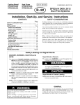
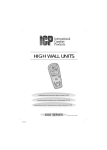
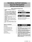
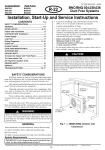
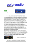
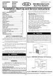
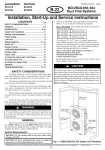
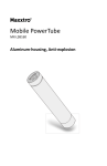
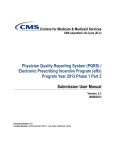
51302618915 0106 421 01 9217 00 Cooling Model DFS2A309J1A DFS2A312J1A DFS2A318K1A Heat Pump DFS2H309J1A DFS2H312J1A DFS2H318K1A DFS2A/H 09,12,18 Duct Free Systems Installation, Start-Up and Service Instructions CONTENTS Page SAFETY CONSIDERATIONS . . . . . . . . . . . . . . . . . . . . . . . . .1 GENERAL . . . . . . . . . . . . . . . . . . . . . . . . . . . . . . . . . . . . . . . . . 1-4 INSTALLATION . . . . . . . . . . . . . . . . . . . . . . . . . . . . . . . . . . . 4-11 Indoor Unit Installation . . . . . . . . . . . . . . . . . . . . . . . . . . . . . 4 Outdoor Unit Installation . . . . . . . . . . . . . . . . . . . . . . . . . . . .6 Power Supply. . . . . . . . . . . . . . . . . . . . . . . . . . . . . . . . . . . . . . . .7 Leak Test . . . . . . . . . . . . . . . . . . . . . . . . . . . . . . . . . . . . . . . . . . . .7 START-UP . . . . . . . . . . . . . . . . . . . . . . . . . . . . . . . . . . . . . . . . . .11 System Checks . . . . . . . . . . . . . . . . . . . . . . . . . . . . . . . . . . . . .11 CARE AND MAINTENANCE. . . . . . . . . . . . . . . . . . . . . . . . .11 Outdoor Units . . . .. . . . . . . . . . . . . . . . . . . . . . . . . . . . . . . . . .11 Indoor Units. . . . . . . . . . . . . . . . . . . . . . . . . . . . . . . . . . . . . . . .11 To Clean the Indoor Unit Front Panel . . . . . . . . . . . . . . .11 To Clean Indoor Coil. . . . . . . . . . . . . . . . . . . . . . . . . . . . . . . .11 Air Filters for Indoor Units . . . . . . . . . . . . . . . . . . . . . . . . . .11 SERVICE . . . . . . . . . . . . . . . . . . . . . . . . . . . . . . . . . . . . . . . . . . .11 TROUBLESHOOTING . . . . . . . . . . . . . . . . . . . . . . . . . . . . 12-15 SAFETY CONSIDERATIONS Installing, starting up, and servicing air-conditioning equipment can be hazardous due to system pressures, electrical components, and equipment location (roofs, elevated structures, etc.). Only trained, qualified installers and service mechanics should install, start-up, and service this equipment. Untrained personnel can perform basic maintenance functions such as cleaning coils. All other operations should be performed by trained service personnel. When working on the equipment, observe precautions in the literature and on tags, stickers, and labels attached to the equipment. Follow all safety codes. Wear safety glasses and work gloves. Keep quenching cloth and fire extinguisher nearby when brazing. Use care in handling, rigging, and setting bulky equipment. Consult local building codes and National Electrical Code (NEC, U.S.A.) for special installation requirements. Max. cable length. Total voltage drop should not exceed 1V. Therefore max. length: For #18 AWG 24.3 Feet (7.4 m) For #16 AWG 37.7 Feet (11.5 m) For #14 AWG 50.0 Feet (18 m) Use only type G or C fuses. Use single length power cable without extension. Allow sufficient space for airflow clearance on condensing units for wiring, refrigerant piping, and servicing unit. See Fig. 1 and 2 for minimum required distances between unit and walls or ceilings. Indoor and outdoor units should be installed at a Maximum line length of 50 ft, and vertical separation of 30 ft. Do not install indoor units near a direct source of heat such as direct sunlight, steam or flame. Do not bury more than 36 in. of refrigerant pipe in the ground. If any section of pipe is buried, there must be a 6 in. vertical rise to the valve connections on the outdoor units. If more than the recommended length is buried, refrigerant may migrate to the cooler buried section during extended periods of system shutdown. This causes refrigerant slugging and could possibly damage the compressor at start-up. LEFT (min.) 6 (0.15m) REAR (min.) 6 (0.15m) FRONT (min.) 2 (0.6m) Before installing or servicing system, always turn off main power to system and install lockout tag on disconnect. There may be more than one disconnect switch. Electrical shock can cause personal injury. TOP (min.) 2 (0.6m) RIGHT (min.) 2 (0.6m) Fig. 1A Outdoor Unit Clearances GENERAL These instructions cover the installation, start-up and servicing of DFC2A/DFC2H outdoor and DFF2A/DFF2H indoor units cooling only and heat pump duct free systems. See Table 1 for parts included. See Tables 2 and 3 for Physical Data. System Requirements IMPORTANT: The Indoor unit & the inter units cable voltage is 30 VDC IMPORTANT: Each refrigerant line must be insulated separately. See line sizing requirements in table 2. LEFT(min.) 6 (0.15m) TOP(min.) 2 (0.6m) REAR(min.) 6 (0.15m) FRONT(min.) 2 (0.6m) RIGHT(min.) 2 (0.6m) Fig. 1B Outdoor Unit Clearances Manufacturer reserves the right to discontinue, or change at any time, specifications or designs without notice and without inc Printed in Israel Pg 1 Table 1 Parts List High Wall Units ITEM QTY Mounting Bracket 1 DIAGRAM DFF2A/DFF2H 09, 12 Long Screws 8 Outdoor Sensor Connecting Cable 1 Absorption Cushions 4 Electric Terminals 8 Remote Controller Rack 1 rack with 2 screws Remote Controller and Batteries 1 or (Available for HEAT PUMP ONLY) ECONOMY Insulation for indoor Fittings 1 Owners Manual 1 1 Wall mounted Receiver RTX DFF2A/DFF2H 18 (OPTIONAL) (Not included) NADA001TW 2 TURBO-JET Table 2 Physical Data Cooling Only DFF2AH09J1A INDOOR UNIT DFF2AH12J1A DFF2AH18J1A COOLING CAPACITY (Btuh) SEER 9,000 13 11,600 13 SYSTEM CHARGE (lb)* MOISTURE REMOVAL (pt/hr) AIRFLOW High Cfm 2.7 2.6 3.1 4.5 4.1 5.3 350 400 670 DIMENSIONS L x H x W (in.) 32 3/32 x 10 15/64 x 7 9/32 NET WEIGHT (lb) OUTDOOR UNIT TUBE CONNECTIONS Vert Lift/Vert Drop/Max Length (ft) 32 3/32 x 10 15/64 x 7 9/32 19.0 27.5 DFC2A309J1A DFC2A312J1A DFC2A318K1A 1/ DIMENSIONS L x H x W (in.) 42 1/2 x 11 5/8 x 7 9/32 19.0 30/30/50 NOMINAL LINE SIZING Mixed Phase...Suction (in.) 19,000 13 30/30/50 1/ 1 4... /2 1 4... /2 28 3/4 X 21 1/4 X 10 7/16 35 7/16 X 25 3/16 X 12 9/32 73 114 NET WEIGHT (lb) 30/30/50 3/ 5 8... /8 43 5/16 X 25 3/16 X 15 3/4 136 LEGEND SEER Seasonal Energy Efficiency Ratio *Units are shipped with a factory charge based on 25 ft of refrigerant lines. Table 3 Physical Data Heat Pump INDOOR UNIT COOLING CAPACITY (Btuh) SEER HEATING CAPACITY (Btuh) HSPF DFF2HH09J1A DFF2HH12J1A DFF2HH18J1A 9,000 13.0 8,600 7.7 11,600 13.0 11,800 7.7 19,000 13.0 18,300 7.7 SYSTEM CHARGE* (lb) 2.7 3.1 4.1 MOISTURE REMOVAL (pt/hr) 2.6 4.5 5.3 AIRFLOW High Cfm 350 400 670 32 3/32 x 10 15/64 x 7 9/32 32 3/32 x 10 15/64 x 7 9/32 DIMENSIONS L x H x W (in.) NET WEIGHT (lb) OUTDOOR UNIT TUBE CONNECTIONS Vert Lift/Vert Drop/Max Length (ft) NOMINAL LINE SIZING Mixed Phase...Suction (in.) DIMENSIONS L x H x W (in.) SHIPPING WEIGHT (lb) 19.0 19.0 DFC2H309J1A DFC2H312J1A 30/30/50 1/ 42 1/2 x 11 5/8 x 7 9/32 30/30/50 1 4... /2 1/ 28 3/4 X 21 1/4 X 10 7/16 1 4... /2 35 7/16 X 25 3/16 X 12 9/32 73 114 LEGEND HSPF Heating Seasonal Performance Factor SEER Seasonal Energy Efficiency Ratio *Units are shipped with a factory charge based on 25 ft of refrigerant lines. NOTE: Standard Ambient Operating Limitations 55 ºF to 125 ºF (12.7 ºC to 51.6 ºC). 3 27.5 DFC2H318K1A 30/30/50 3/ 5 8... /8 43 5/16 X 25 3/16 X 15 3/4 136 6" (0.15m) min. 8" (0.2m) 8" (0.2m) min. min. 3 2 1 4 Fig. 3 Refrigerant Lines 6'-8'3" (1.8-2.5m) 09, 12 25 17 11 16 9 23 32 2 19 32 3 5 32 3½ 1¾ 21 8 Fig. 2 Indoor Unit Clearances 11 INSTALLATION 32 10 1 4 1¾ Plan the installation carefully to avoid component failures and make installation easier. 5 10 5 8 Indoor Unit Installation 2¾ Fig. 4 Mounting Bracket DFF2A/DFF2H 09, 12 REFRIGERANT LINE ROUTING The refrigerant lines may be routed in any of the four directions shown in Fig. 3. 18 INSTALL THE MOUNTING BRACKET 2¾ 1. Carefully remove the mounting bracket, which is connected to the back of the indoor units base with screws. 1 2. Position the mounting bracket on the wall and level it using a spirit level (see Fig. 2 for minimum required clearance distances). 3. Mark the four drilling holes on the wall, as they appear in Fig. 4. 4. Drill the holes, insert the wall plugs and use four long screws to attach the mounting bracket to the wall. 5. Check that the bracket is leveled and securely fastened to the wall. DRILL A HOLE IN THE WALL FOR DRAINAGE AND INTER-UNIT CONNECTIONS To make the connections between the indoor and outdoor units, drill a 3-in. hole through the wall for the refrigerant lines, drainage hose and control cable passage as shown in Fig. 5. 1. Mark the center of the hole to be drilled according to the refrigerant line routing used and dimensions shown in Fig. 4. 2. Make sure to drill outwards and downwards, so that the opening in the outside wall is at least 1/2-in. lower than the opening on the inside. 3. Make sure the drainage hose is at the bottom side of the hole. 4 . If refrigerant line route no. 1, 2 or 4 are used, use a small saw blade to carefully remove the corresponding plastic covering on the side panel. 5. Run the outdoor sensor cable, electrical cable, refrigerant lines, and drainage tube through the hole. 6. Fill the remaining wall hole gap with an appropriate sealant material. 35 15 2¾ 7¾ 3½ 2 2 13¾ 6 2¾ Fig. 4 Mounting Bracket DFF2A/DFF2H 18 3-IN. (Optional for HEAT PUMP SYSTEMS) OUTDOOR SENSOR CABLE REFRIGERANT LINES 1/2.IN. MIN INDOOR OUTDOOR ELECTRICAL CABLE Fig. 5 Drill Holes 4 DRAINAGE TUBE WIRE THE INDOOR UNIT REASSEMBLE 1. Strip the cables back 1/ 4 inch. 2. Remove the unit's front panel by lifting the lower part and pulling it gently outward and upward. See Fig. 6. 3. Remove the two screws from the control box cover and take off the cover. See Fig. 7. Save the screws to reassemble. NOTE: In general wiring the indoor unit does not require the removal of the grille frame but in case of need do as follow: 4. Remove the two screws from the air discharge opening. Save the screws to reassemble. See Fig. 7A. 5. Pull downwards and outwardston the bottom of the grille and gently raise the frame of the top of the unit. 6 . Once all covers are off, mount the unit onto the wall mounting bracket. See Fig. 8 . NOTE: Leave covers off until after the Making Drainage Connections section. 7 . Route the interconnecting units electric cable and the outdoor sensor cable towards the lower right hand corner of the indoor unit. 8. Make sure that the wires are connected in accordance with the wiring diagram on the inside of the unit front cover or within this instruction manual. 9. Secure the control cables to the strain relief. 10. For heat pump systems only, connect the outdoor sensor TH3 to its mating black terminal. See Fig. 9. 1. Connect the display connector to the display panel printed circuit board. 2. Put the control box cover and grille frame back on using the appropriate screws (Steps 3 and 4 of Wire the Indoor Unit section). Put the grille insert back on. Fig. 6 Remove Grille Insert POWER/AIRCOND POWER/AIRCOND TIMER TIMER FILTER FILTER IRIR RECEIVER RECEIVER Fig. 7 Remove Control Cover Make sure that all wires and screws are firmly fastened. Loose wires or connections can cause damage and present a fire hazard. MAKE DRAINAGE CONNECTIONS 1. Connect the unattached end of the drainage tube to the drainage hose outlet. 2. Seal the drainage connection to prevent leakage. 3. Make sure there are no kinks, U bends or flattened sections in the tube. 4. Check that the drainage functions properly. Fill the pan below the units coil with water and observe that it freely drains out. 5. Make sure the drainage hose is at the bottom side of the wall through-hole (see Fig. 5). Fig. 7A---Remove the screws from the air discharge opening. Mount the indoor unit on the mounting bracket 1 2 Gently push with the arrow direction Fig. 8 Indoor Unit Mounting Standard Dip Switches status from the factory HEAT PUMP Model-12 DIP Switches location (on the Control Box side) HEAT PUMP Models-09,18 DIP Switches location (on the Control Box side) COOLING ONLY Model-12 DIP Switches location (on the Control Box side) COOLING ONLY Models-09,18 DIP Switches location (on the Control Box side) ON 123456 Inter unit terminal block 30 VDC 123456 Display connection ON ON 123456 TH1 ON TH2 TH3 (Heat pump only) 123456 Inter unit cable clamp Fig. 9 Outdoor Sensor Connection 5 CONNECT REFRIGERANT LINES Connect the ends of the refrigerant lines to their appropriate fittings, following these guidelines: To connect the refrigerant lines use only L type sealed, dehydrated copper refrigerant tubing. No other type of tubing may be used. Use of other types of tubing will void the manufacturers warranty. Do not open service valves or remove protective caps from tubing ends until all the connections are made. Take care to avoid kinks or flattening of the tubing. Bend tubing with special bending tools to avoid the formation of sharp bends. Keep the tubing free of dirt, sand, moisture and other contaminants to avoid damaging the refrigerant system. Avoid sags in the suction line to prevent the formation of oil traps. Insulate both refrigerant lines separately with 3/8-in. walled thermal pipe insulation. Inserting the tubing into the insulation before making the connections can save time and improve insulation. The suction and mixed phase lines should never come in direct contact. ATTACH THE REMOTE CONTROLLER RACK 1. Use the two screws supplied with the controller to attach the rack to the wall in the location selected by the customer (see Fig. 10 ). 2. Install batteries in the remote control. 3. Place remote control into remote control rack. 4. For remote control operation, refer to the unit Owners Manual. MAKE REFRIGERANT PIPING CONNECTIONS (OUTDOOR UNIT) To connect the refrigerant lines: Use only L type sealed, dehydrated copper refrigerant tubing. No other type of tubing may be used. Use of other types of tubing will void the manufacturers warranty. Do not open service valves or remove protective caps from tubing ends until all the connections are made. Bend tubing with special bending tools to avoid the formation of sharp bends. Take care to avoid kinks or flattening of the tubing. Keep the tubing free of dirt, sand, moisture, and other contaminants to avoid damaging the refrigerant system. Avoid sags in the suction line to prevent the formation of oil traps. Insulate each tube with 3/8-in. walled thermal pipe insulation. Inserting the tubing into the insulation before making the connections will save time and improve installation The suction and mixed-phase lines should never come in direct contact. POWER SUPPLY TERMINAL BLOCK INTER UNIT TERMINAL BLOCK L2 L1 208-230 VAC 1 FAN (H) 3 R.V.S 4 HIGH/LOW VOLTAGE METAL BARRIER 24 VAC 2 FAN (L) COMP. 5 COMMON 6 L2 L1 280-230 VAC 1 3 4 COMP. 5 COMMON 1 FAN (H) 2 FAN (L) 3 R.V.S 4 24 VAC 2 FAN (L) R.V.S 24 VAC FAN (H) COMP. 5 COMMON Outdoor Unit Installation TH3 SENSOR (HEAT PUMP ONLY) METAL CONDUIT CONNECTION PLATE NOTE: The outdoor unit must be installed on a solid surface (mounting base). 1. Place the rubber absorption cushions (supplied with the outdoor unit) under the units feets to prevent vibrations. 2. Fasten the outdoor unit legs to the mounting base, as shown in Fig. 12. The cushion goes between the legs and the mounting base. 3. Be sure that the unit is leveled. POWER SUPPLY CABLE INTER UNIT CABLE 4 ABSORPTION CUSHION TO BE PUT UNDER EACH FEET Fig. 12 --- Legs Mounting Base and Wiring Outdoor Units Models: DFC2A/H 12, 18 REMOTE CONTROL REMOTE CONTROL RACK ECONOMY TURBO-JET Fig. 10 Attach Rack to the Wall (OPTIONAL) NADA001TW Fig. 11 Wall Mounted Unit - RTX 6 1 2 3 4 COMP (+30V) 30 VDC FAN RVS 5 L2 DC RTN 6 L1 115 VAC 1 6 Neutral 7 Contact 8 h) S(3p 9 h) T(3p d HI spee 2 p Com 3 RVS d4 spee Med d5 spee Low p. INDOOR UNIT 09,12,18 * 6 FUSE 5 4 3 2 1 PRESSURE COMPRESSOR IMPEDANCE TH1 TH2 TH3 POWER/AIRCOND. Fig. 12A --- Legs Mounting Base and Wiring POWER/AIRCOND. AUTO OFF REMOTE TIMER TIMER Outdoor Units FILTER Model DFC2A/H 09 POWER/AIRCOND POWER/AIRCOND IR RECEIVER IR RECEIVER TIMER TIMER FILTER FILTER IR RECEIVER IR RECEIVER FILTER Plastic Cover Fig. 12B --- Indoor unit Leds and Wiring 3. Disconnect the vacuum pump. Unit should maintain 500 microns for 5 minutes. FLARING AND CONNECTING REFRIGERANT LINES 1. Remove the protective cap from the flare fitting. 2. Remove the protective cap from the tubing and cut to the required length. Be sure that the cut is perpendicular and clean, without burrs. 3. Slip the flare nut on the tubing and flare the tube end using standard flaring tools. 4. Tighten the nut until resistance is met. Mark the nut and the fitting. Using a suitable wrench tighten an additional 1/ turn. Use the following specified torque, according to 4 connection size: Mixed-Phase line: Suction line: 1/ -in. (12.3 ft-lb) 1/ -in. (36 ft-lb) 4 2 3/ -in. (29 ft-lb) 5/ -in. (47 ft-lb) 8 8 NOTE: The service valves on the outdoor unit must remain closed until all 4 connections have been made. EVACUATE TUBING AND CHARGE THE SYSTEM When all the fittings are connected, air must be expelled, then refrigerant charge must be checked and adjusted. Follow the steps below. 1. Open the service port cap on the suction line valve (large valve). 2. Connect the vacuum pump to the service port via the pressure gage and evacuate to 500 microns to eliminate contamination and moisture. 4. Remove the service port caps from the mixed-phase valve and suction line valve 5. Open the mixed-phase valve (small valve) with an Allen wrench. 6. Open the suction line valve (large valve) with an Allen wrench. 7. The outdoor unit is supplied with sufficient R-22 refrigerant up to 25 ft piping length. Add 0.9 oz of refrigerant for each additional 3 ft of tubing used. 8. Make sure that the valves are properly opened. Be careful not to open them more than required as this may damage the thread. 9. Replace the service port cap. Using refrigerant oil, lubricate the cap beam and hand tighten until resistance is met. Use a suitable wrench to tighten the cap by an additional 1/ turn. 2 Power Supply See Tables 4 and 5 for electrical data and Fig. 13-16 for system wiring diagrams. Leak Test Leak test all fittings with appropriate test equipment. 7 Table 4 — Electrical Data, Indoor Units — 115, 208/230-1-60 UNIT 09,12 18 DFF2A/DFF2H DFF2A/DFF2H MCA* MOCP* FULL LOAD AMPS FAN MOTOR AMPS 0.1 0.1 10 10 1.8 2.4 1.2 2.0 LEGEND MCA — Minimum Circuit Amps MOCP — Maximum Overcurrent Protection COMPRESSOR LOCKED ROTOR AMPS COMPRESSOR AMPS NA NA . *If indoor unit is powered from outdoor terminal block, the MOCP for the outdoor unit is for both sections NOTE: Specifications and performance data are subject to change without notice. Table 5 — Electrical Data, Outdoor Units — 115, 208/230-1-60 UNIT DFC2A/DFC2H DFC2A/DFC2H 09,12 18 MCA* MOCP* 10 10 20 20 FULL LOAD AMPS FAN MOTOR AMPS 8 8 1 1 LEGEND MCA — Minimum Circuit Amps MOCP — Maximum Overcurrent Protection *If indoor unit is powered from outdoor terminal block, the MOCP for the outdoor unit is for both sections NOTE: Specifications and performance data are subject to change without notice. 8 COMPRESSOR AMPS 6 6 COMPRESSOR LOCKED ROTOR AMPS 42, 58 42 J12 1 3 K7 K9 FAN L RED 7130C CC -Compressor Capacitor COMP-Compressor FC -Fan Capacitor GRD -Ground RVS -Reversing Valve Solenoid HLTV -Heating Low Temp. Valve TB -Terminal Block TH -Thermistor TAC 670 control WH FANH BLUE +30V +12V RED -12V BLK COMP. RVS H.L.T.V FAN 5 6 4 3 2 1 J4 J1 123 VSP M LEGEND BLDC MOTOR GRD WHT+ 12 VDC YEL RED GR/YEL *** -16 AWG ** -14 AWG * -12 AWG ALL OTHER WIRES 18 AWG -Splice -Terminal (Unmarked) Factory Wiring Field Control Wiring Field Power Wiring Accessory or Optional Wiring TAC 672 Motor Control 5 4 3 2 1 J3 1 3 J5 TB 1 2 WH 3 OR 4 RED 5 GREEN 6 BLK YEL **GREEN **OR **RED **YEL **WH **BLK 0 GRD GRD DC RTN +30 VDC HLTV COMP 1 RVS FAN ***RED Mains AC Supply ~ L2 L1 1 2 3 4 5 6 TB RVS COMP 1 DC RTN HLTV FAN DC RTN (-) DC Out (+) TAC 673 Relay Board 1 2 3 4 5 J1 RVS FAN AC IN BLK C R COMP. S CC HLTV FC 9 *OR BLK *BLUE BLK RVS BLK DC ~ RTN GRD FAN MOTOR 247915 WHT 0 NOTES: 1. If any of the original wire furnished must be replaced, it must be replaced with Type 90° C wire or its equivalent. 2. Wire in accordance with National Electrical Code (NEC) and local codes. 3. Thermistor wiring cable 32 ft long provided with indoor unit. 4. Compressor and fan motors are protected by internal thermal overloads. ***GREEN ~ BR 0 BLUE FUSE 6A 30VDC Power Supply DC Out *** GR/YEL GR/YEL * BLUE GREEN GREEN * BR PH-AC COMP 1 K1 K2 K3 K4 TB 1 BLK TH3 Fig. 13 Heat Pump System Wiring Schematic DFF2A/DFF2H 09 Fan Coil with DFC2A/DFC2H 09 Condensing Unit 6 FAN T BLK 4 5 1 J11 2 3 4 5 J8 J18 K8 J14 K2 K1 K5 K6 J7 TAC 671 Main Board STEPPER MOTOR J6 TH3 *BR TH3 *GR/YEL TH2 *BLK TH1 *BLUE OUTDOOR UNIT *BR *BR Model 09 Wiring Diagram WHT BRN INDOOR UNIT GR/YEL BLK OR BRN WH YEL/GR RED BLK TB J12 1 3 K7 K9 FAN L RED 7137D CC -Compressor Capacitor COMP-Compressor FC -Fan Capacitor GRD -Ground RVS -Reversing Valve Solenoid HLTV -Heating Low Temp. Valve TB -Terminal Block TH -Thermistor TAC 670 control WH FANH BLUE +30V +12V RED -12V BLK COMP. RVS H.L.T.V FAN 5 6 4 3 2 1 J4 J1 123 VSP BLDC MOTOR M LEGEND WHT+ 12 VDC YEL RED + 30 VDC BLK DC RTN *** -16 AWG ** -14 AWG * -12 AWG ALL OTHER WIRES 18 AWG -Splice -Terminal (Unmarked) Factory Wiring Field Control Wiring Field Power Wiring Accessory or Optional Wiring TAC 672 Motor Control 5 4 3 2 1 J3 1 3 J5 GR/YEL WH OR GRD TB 1 2 3 4 RED 5 GREEN 6 BLK YEL **GREEN **OR **RED **YEL **WH **BLK 0 GRD DC RTN +30 VDC HLTV COMP 1 RVS FAN TB ***RED Mains AC Supply ~ L2 L1 1 2 3 4 5 6 FAN RVS COMP 1 DC RTN HLTV DC RTN (-) DC Out (+) TAC 673 Relay Board 1 2 3 4 5 J1 RVS FAN AC IN BLK C R COMP. S CC HLTV BLK FC *OR BLK *BLUE BLK RVS BLK 10 DC ~ RTN GRD FAN MOTOR 123456 WHT 0 NOTES: 1. If any of the original wire furnished must be replaced, it must be replaced with Type 90° C wire or its equivalent. 2. Wire in accordance with National Electrical Code (NEC) and local codes. 3. Thermistor wiring cable 32 ft long provided with indoor unit. 4. Compressor and fan motors are protected by internal thermal overloads. ***GREEN ~ BR 0 BLUE FUSE 6A 30VDC Power Supply DC Out *** GR/YEL GR/YEL * BLUE GREEN GREEN * BR PH-AC COMP 1 K1 K2 K3 K4 TB 1 TH3 Fig. 14 Heat Pump System Wiring Schematic DFF2A/DFF2H 12,18 Fan Coil with DFC2A/DFC2H 12,18 Condensing Unit 6 FAN T BLK 4 5 1 J11 2 3 4 5 J8 J18 K8 J14 K2 K1 K5 K6 J7 TAC 671 Main Board STEPPER MOTOR J6 TH3 *BR TH3 *GR/YEL TH2 *BLK TH1 *BLUE OUTDOOR UNIT *BR *BR Models 12 / 18 Wiring Diagram WHT BRN WH BRN RED YEL/GR INDOOR UNIT GR/YEL BLK BLK TB START-UP Indoor Units System Checks 1. Conceal the tubing where possible. 2. Make sure that the drainage tube slopes downward along its entire length. 3. Ensure all tubing and connections are properly insulated. 4. Fasten tubes to the outside wall. 5. Seal the hole through which the cables and tubing pass. 6. Connect the air conditioner to the power source and turn it on. 7. Check all air conditioner operating modes. Refer to Owners Manual for operating details. INDOOR UNIT 1. Do all the remote controller buttons function properly? 2. Do the display panel lights work properly? 3. Does the air deflection louver function properly? 4. Does the drainage work? OUTDOOR UNIT 1. Are there unusual noises or vibrations during operation? 2. Is noise, drain water or airflow from the unit likely to disturb the neighbors? 3. Are there any gas leaks? EXPLAIN THE FOLLOWING ITEMS TO THE CUSTOMER, WITH THE AID OF THE OWNERS MANUAL: 1. How to turn the air conditioner on and off; selecting cooling, heating and other operating modes; setting a desired temperature; setting the timer to automatically start and stop air conditioner operation; and the other features of the remote controller and display panel. 2. How to remove and clean the air filter. 3. How to set the air deflection louver. 4. Explain care and maintenance. 5. Present the Owners Manual and installation instructions to the customer. To avoid the possibility of electric shock, before performing any cleaning and maintenance operations, always turn off power to the system by pressing the ON/OFF button on the remote control and turn off the separate disconnect switch located near the unit. If the indoor unit is on a separate switch, be sure to turn this disconnect off as well. Do not wash filter in water over 120 F (to avoid shrinkage). Do not expose filter to fire (to avoid fire damage). Do not expose filter to direct sunlight. Clean filter more frequently when air is extremely dirty. Do not attempt to clean or service components in control box. To Clean the Indoor Unit Front Panel If the front panel of the unit becomes dirty or smudged, wipe the outside of the panel with a soft dry cloth. Use a mild liquid detergent and wipe off carefully with a dry cloth. To Clean Indoor Coil To clean the coil, remove indoor unit front panel and vacuum the coil fins, using care not to bend or damage fins. LUBRICATION The indoor-fan, automatic air sweep, and the outdoor-fan motors are factory lubricated and require no oiling. Air Filters for Indoor Units Operating your system with dirty air filters may damage the indoor unit and, in addition, can cause reduced performance, intermittent system operation, frost build up on the indoor coil, and blown fuses. Inspect and clean or replace the air filters monthly. CARE AND MAINTENANCE The following may be performed by the equipment owner. TO REMOVE AIR FILTERS Open the unit's front panel by lifting the lower part and pulling it gently outward and upward. Pull out the filters. Outdoor Units Before performing recommended maintenance, be sure unit main power switch is turned off. Failure to do so may result in electric shock or injury from rotating fan blade. TO CLEAN OR REPLACE FILTERS Filters can be vacuumed or washed in warm water. Shake filter to remove any excess water, and replace it back. If the filter has begun to break down or is torn, replace it. Replacement filters are available through a local dealer. CLEANING COILS Coil should be washed out with water or blown out with compressed air. Clean coil annually or as required by location and outdoor air conditions. Inspect coil monthly and clean as required. Fins are not continuous through coil sections. Dirt and debris may pass through first section, become trapped between the row of fins and restrict outdoor unit airflow. Use a flashlight to determine if dirt or debris has collected between coil sections. Clean coil as follows: 1. Turn off unit power and install lockout tag. 2. Using a garden hose or other suitable equipment, flush coil from the outside to remove dirt. Be sure to flush all dirt and debris from drain holes in base of unit. Fan motors are waterproof. SERVICE 11 The following should be performed by a qualified service technician. Clean Condensate Drains Clean all drains and drain pans at the start of each cooling season. Check the flow by pouring water into the drain. Clean or Replace Drain Pan The drain pan should only be cleaned or replaced by a qualified service technician. 1. Place a plastic sheet on the floor to catch any water that may spill from the drain pan. 2. Remove the intake grille and distribution assembly. 3. Remove the condensate water in the drain pan by letting water drain into a 3-gallon bucket. TROUBLESHOOTING (Tables 6-8, and Fig. 17) Be sure to check for broken wires or loose cable lugs before troubleshooting system. Table 6 Service Indicators LAMP STATUS INDICATION 1 Flash Faulty TH1 Sensor 2 Flashes Faulty TH2 Sensor 3 Flashes Low Pressure 4 Flashes High Pressure 5 Flashes Low Voltage 6 Flashes High Voltage CORRECTION ACTION Check the TH1 thermistor for correct resistance. Check for proper connection. Replace thermistor if necessary. Check the TH2 thermistor for correct resistance. Check for proper connection. Replace thermistor if necessary. Check system pressures. Check refrigerant charge. Check thermistors (TH1 and TH2) for correct resistance. Check system pressures. Check refrigerant charge. Check thermistors (TH1 and TH2) for correct resistance. Check operating voltage. Check electrical connections. Check operating voltage. Check electrical connections. OPERATION LED. INDICATES ERROR VA C POWER LED. OFF WHEN SYSTEM IS OPERATING AND FLASHES WHEN SYSTEM IS IN ERROR. (DOES NOT INDICATE ERROR CODE) Fig. 17 Indicator Lights CLEAN FILTER INDICATOR. FLASHES AFTER 250 HOURS OF OPERATION 12 Table 7 DFS2A/DFS2H Thermistor TH-1, TH-2, and TH-3 Temperature to Resistance Conversion TEMPEATURE (0F) TEMPERATURE (0C) 4.0 2.2 0.4 1.4 3.2 5.0 6.8 8.6 10.4 12.2 14.0 15.8 17.6 19.4 21.2 23.0 24.8 26.6 28.4 30.2 32.0 33.8 35.6 37.4 39.2 41.0 42.8 44.6 46.4 48.2 50.0 51.8 53.6 55.4 57.2 59.0 60.8 62.6 64.4 66.2 68.0 69.8 71.6 73.4 75.2 77.0 78.8 80.6 82.4 84.2 86.0 87.8 89.6 91.4 93.2 95.0 96.8 98.6 20 19 18 17 16 15 14 13 12 11 10 9 8 7 6 5 4 3 2 1 0 1 2 3 4 5 6 7 8 9 10 11 12 13 14 15 16 17 18 19 20 21 22 23 24 25 26 27 28 29 30 31 32 33 34 35 36 37 TEMPERATURE TOLERANCE (0F) ±2.0 ±2.0 ±2.0 ±2.0 ±2.0 ±2.0 ±2.0 ±2.0 ±2.0 ±2.0 ±1.8 ±1.8 ±1.8 ±1.8 ±1.8 ±1.8 ±1.8 ±1.8 ±1.8 ±1.8 ±1.8 ±1.8 ±1.8 ±1.8 ±1.8 ±1.8 ±1.8 ±1.8 ±1.8 ±1.8 ±1.8 ±1.8 ±1.8 ±1.6 ±1.6 ±1.6 ±1.6 ±1.6 ±1.6 ±1.6 ±1.6 ±1.6 ±1.6 ±1.6 ±1.6 ±1.6 ±1.6 ±1.6 ±1.6 ±1.8 ±1.8 ±1.8 ±1.8 ±1.8 ±1.8 ±1.8 ±2.0 ±2.0 TEMPERATURE TOLERANCE (0C) ±1.1 ±1.1 ±1.1 ±1.1 ±1.1 ±1.1 ±1.1 ±1.1 ±1.1 ±1.1 ±1.0 ±1.0 ±1.0 ±1.0 ±1.0 ±1.0 ±1.0 ±1.0 ±1.0 ±1.0 ±1.0 ±1.0 ±1.0 ±1.0 ±1.0 ±1.0 ±1.0 ±1.0 ±1.0 ±1.0 ±1.0 ±1.0 ±1.0 ±0.9 ±0.9 ±0.9 ±0.9 ±0.9 ±0.9 ±0.9 ±0.9 ±0.9 ±0.9 ±0.9 ±0.9 ±0.9 ±0.9 ±0.9 ±0.9 ±1.0 ±1.0 ±1.0 ±1.0 ±1.0 ±1.0 ±1.0 ±1.1 ±1.1 NOTE: Resistance tolerance ± 3%. 13 MINIMUM RESISTANCE (KΩ ) 30.89 29.46 28.12 26.84 25.64 24.49 23.40 22.38 21.40 20.47 19.59 18.74 17.94 17.17 16.44 15.75 15.10 14.47 13.87 13.31 12.77 12.25 11.75 11.28 10.83 10.40 9.986 9.595 9.222 8.866 8.526 8.197 7.883 7.583 7.296 7.022 6.761 6.510 6.271 6.042 5.822 5.611 5.408 5.214 5.028 4.850 4.675 4.508 4.347 4.193 4.046 3.904 3.767 3.637 3.511 3.391 3.275 3.164 MEAN RESISTANCE (KΩ) 32.44 30.93 29.51 28.16 26.88 25.66 24.52 23.43 22.39 21.41 20.48 19.59 18.74 17.93 17.16 16.43 15.74 15.08 14.46 13.86 13.29 12.74 12.22 11.73 11.25 10.80 10.370 9.960 9.569 9.196 8.840 8.496 8.167 7.853 7.553 7.267 6.993 6.731 6.481 6.242 6.013 5.793 5.581 5.379 5.185 5.000 4.821 4.650 4.486 4.329 4.179 4.033 3.894 3.760 3.631 3.508 3.390 3.276 MAXIMUM RESISTANCE (KΩ) 34.05 32.45 30.94 29.51 28.15 26.87 25.66 24.50 23.41 22.38 21.40 20.45 19.56 18.71 17.90 17.13 16.40 15.71 15.05 14.42 13.83 13.25 12.70 12.18 11.68 11.21 10.76 10.33 9.921 9.530 9.157 8.797 8.453 8.125 7.812 7.513 7.227 6.954 6.693 6.444 6.205 5.975 5.755 5.544 5.343 5.150 4.968 4.793 4.626 4.466 4.312 4.163 4.020 3.884 3.752 3.626 3.505 3.389 Table 7 DFS2A/DFS2H Thermistor TH-1, TH-2, and TH-3 Temperature to Resistance Conversion (cont) TEMPEATURE (0F) TEMPERATURE (0C) 100.4 102.2 104.0 105.8 107.6 109.4 111.2 113.0 114.8 116.6 118.4 120.2 122.0 123.8 125.6 127.4 129.2 131.0 132.8 134.6 136.4 138.2 140.0 141.8 143.6 145.4 147.2 149.0 150.8 152.6 154.4 156.2 158.0 38 39 40 41 42 43 44 45 46 47 48 49 50 51 52 53 54 55 56 57 58 59 60 61 62 63 64 65 66 67 68 69 70 TEMPERATURE TOLERANCE (0F) ±2.0 ±2.0 ±2.0 ±2.0 ±2.0 ±2.2 ±2.2 ±2.2 ±2.2 ±2.2 ±2.3 ±2.3 ±2.3 ±2.3 ±2.3 ±2.3 ±2.3 ±2.5 ±2.5 ±2.5 ±2.5 ±2.5 ±2.5 ±2.7 ±2.7 ±2.7 ±2.7 ±2.7 ±2.9 ±2.9 ±2.9 ±2.9 ±2.9 TEMPERATURE TOLERANCE (0C) ±1.1 ±1.1 ±1.1 ±1.1 ±1.1 ±1.2 ±1.2 ±1.2 ±1.2 ±1.2 ±1.3 ±1.3 ±1.3 ±1.3 ±1.3 ±1.3 ±1.3 ±1.4 ±1.4 ±1.4 ±1.4 ±1.4 ±1.4 ±1.5 ±1.5 ±1.5 ±1.5 ±1.5 ±1.6 ±1.6 ±1.6 ±1.6 ±1.6 NOTE: Resistance tolerance ± 3%. 14 MINIMUM RESISTANCE (KΩ ) 3.058 2.956 2.857 2.762 2.671 2.583 2.498 2.417 2.339 2.264 2.192 2.122 2.055 1.990 1.928 1.867 1.809 1.753 1.699 1.647 1.597 1.549 1.503 1.458 1.414 1.372 1.332 1.293 1.255 1.219 1.184 1.150 1.117 MEAN RESISTANCE (KΩ) 3.167 3.062 2.961 2.864 2.770 2.679 2.593 2.509 2.429 2.352 2.227 2.206 2.137 2.070 2.006 1.943 1.883 1.826 1.770 1.717 1.665 1.615 1.567 1.521 1.476 1.432 1.391 1.350 1.311 1.274 1.237 1.202 1.168 MAXIMUM RESISTANCE (K Ω) 3.277 3.169 3.066 2.966 2.870 2.777 2.688 2.602 2.520 2.441 2.364 2.291 2.220 2.151 2.085 2.021 1.959 1.900 1.842 1.787 1.734 1.683 1.633 1.585 1.539 1.494 1.451 1.409 1.369 1.330 1.292 1.256 1.221 Table 8 General System Troubleshooting Guide SYMPTOM PROBABLE CAUSE Power supply from outdoor unit to indoor unit is not connected. Check for proper connection of power at disconnect. Power supply to unit not connected (POWER LED Off). Unit Fails to Start. Fuse blown (POWER LED Off). ON/SEND button has not been pressed. Indoor unit does not receive transmitted commands. The selected mode is Fan Only, or Cool when heating is desired. Only Indoor Fan Works when Cooling or Heating is Desired. NOTE: Indoor fan runs continuously in cooling mode. Temperature is set to a value which is too high (in Cool mode). Only Indoor Fan Motor and Outdoor Fan Motor are Working. No Cooling and/or Heating Takes Place. No Air Supply at Indoor Unit (Compressor Operates). Low Capacity. In Heat Mode, Only Compressor Runs. Outdoor and Indoor Fan Motors are Stopped. Water Accumulates and Overflows from Evaporator Drain Pan. Unit Does Not Operate in Desired Mode. The Unit Receives Interference from Other Remote Control or the Remote Control Interferes with Other Instruments. CORRECTIVE ACTION Overload safety device on compressor is cut out due to high temperature. Compressor run capacitor is burnt. Compressor winding shorted. Indoor fan motor is blocked or turns slowly. Indoor fan motor capacitor is burnt. Indoor fan motor winding is burnt. In Heat mode: Delayed start for indoor fan motor. Clogged air filters. Lack of refrigerant. Ice formation on the evaporator coil. Clogged air filters. A/C operating in defrost cycle. Reset circuit breaker or replace line fuse. Press ON/SEND button on remote control. Make sure that nothing is blocking the remote control transmission to the unit. Check if the remote control is in the desired mode. If not, select the correct mode (refer to User manual). Also note that every 15 minutes (maximum) the compressor will be switched minimally on for 3 minutes. Observe the temperature setting on the remote control. Also note that each 15 minutes (maximum), the compressor will be switched on minimally for 3 minutes. Switch off power and try again after one hour. Replace compressor run capacitor. Replace compressor. 1. Check voltage. Repair wiring if necessary. 2. Check indoor fan wheel if tight on motor shaft. Tighten if necessary. Replace indoor fan motor capacitor. Replace indoor fan motor. Normal software delay (maximum of 20 sec). Clean filters. Unit must be charged (according to the nameplate) after localizing the gas leak. Clean filters. Wait 10 minutes (maximum) until the unit resumes normal operation. Drain pan pipe or hose is clogged or the spout of drain pan is clogged. Disassemble plastic drain pipe from spout of evaporator drain pan. Flush with clean water. The unit is in the Auto. (emergency) mode. Faulty remote control settings. Push button once to cancel Auto. (emergency) mode. 1. If remote control symbols respond to the commands correctly, check the unit ID Code (Standard or Alternative). Refer to Changing Unit ID Code in the Owner's Manual. 2. If Cool commands are OK, but Heat symbol is skipped on LCD, refer to setting the remote to cooling only or heat pump on the Owner's Manual. 3. Replace remote control. Replace remote control batteries. Modify the Remote Control IR transmission code. Refer to Changing Unit ID Code in the Owners Manual. Remote control low battery. Common Infrared Code. Copyright 2006 ICP International Comfort Products Manufacturer reserves the right to discontinue, or change at any time, specifications or designs without notice and without incurring obligations. Printed in Israel Pg 15