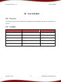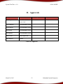
1
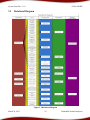
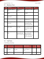
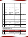
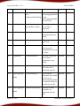
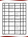
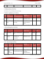
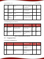
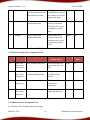
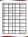
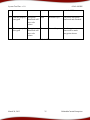
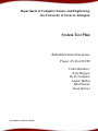
Department of Computer Science and Engineering
the University of Texas at Arlington
System Test Plan
BehindtheCurtain Enterprises
Project AVALANCHE
Team Members:
Kyle Burgess
Kyle Crumpton
Austen Herbst
Bilal Nawaz
Jason Sprowl
Last Updated: 3/24/2013 7:00 pm
System Test Plan – v1.0
AVALANCHE
Table of Contents
Document Revision History ........................................................................................................................5
List of Figures..............................................................................................................................................6
List of Tables ...............................................................................................................................................7
1. Introduction..........................................................................................................................................8
1.1 Document Overview .....................................................................................................................8
2.
1.2
Purpose..........................................................................................................................................8
1.3
Scope.............................................................................................................................................8
1.4
Acronyms ......................................................................................................................................8
References..........................................................................................................................................10
2.1 Overview..........................................................................................................................................10
2.2 System Requirement Specification..................................................................................................10
2.3 Architecture Design Specification ...................................................................................................11
2.4 Detailed Design Specification .........................................................................................................17
3.
4.
Test Items...........................................................................................................................................21
3.1 Overview.....................................................................................................................................21
3.2
Relational Diagram .....................................................................................................................22
3.3
Hardware Tests ...........................................................................................................................23
3.4
Unit Tests ....................................................................................................................................23
3.5
Component Tests.........................................................................................................................28
3.6
Integration Tests..........................................................................................................................31
3.7
System Verification Tests ...........................................................................................................32
Risks ..................................................................................................................................................33
4.1 Overview.....................................................................................................................................33
4.2
5.
Risk Table ...................................................................................................................................33
Testable Features ...............................................................................................................................36
5.1 Overview.....................................................................................................................................36
5.2
Customer Requirements..............................................................................................................36
March 24, 2013
2
BehindtheCurtain Enterprises
System Test Plan – v1.0
AVALANCHE
5.3
Packaging Requirements.............................................................................................................39
5.4
Performance Requirements .........................................................................................................40
5.5
Safety Requirements ...................................................................................................................41
5.6
Maintenance and Support Requirements ....................................................................................41
5.7
Other Requirements ....................................................................................................................42
6. Non Tested Requirements.....................................................................................................................44
6.1 Overview.....................................................................................................................................44
7.
8.
9.
6.2
Customer Requirements..............................................................................................................44
6.3
Packaging Requirements.............................................................................................................44
6.4
Performance Requirements .........................................................................................................44
6.5
Safety Requirements ...................................................................................................................44
6.6
Maintenance and Support Requirements ....................................................................................45
6.7
Other Requirements ....................................................................................................................45
Overall Test Strategy .........................................................................................................................46
7.1 Overview.....................................................................................................................................46
7.2
Overall Test Strategy ..................................................................................................................46
7.3
Methodology ...............................................................................................................................46
7.4
Testing Metrics ...........................................................................................................................47
7.5
Testing Requirements .................................................................................................................47
Acceptance Criteria ...........................................................................................................................48
8.1 Overview.....................................................................................................................................48
8.2
Hardware Tests ...........................................................................................................................48
8.3
Unit Tests ....................................................................................................................................48
8.4
Component Tests.........................................................................................................................48
8.5
Integration Tests..........................................................................................................................49
8.6
System Verification Tests ...........................................................................................................49
Test Deliverables ...............................................................................................................................50
March 24, 2013
3
BehindtheCurtain Enterprises
System Test Plan – v1.0
AVALANCHE
9.1
Overview.....................................................................................................................................50
9.2
Deliverables ................................................................................................................................50
10.
Test Schedule..................................................................................................................................52
10.1
Overview .................................................................................................................................52
10.2
11.
Schedule ..................................................................................................................................52
Approvals........................................................................................................................................53
March 24, 2013
4
BehindtheCurtain Enterprises
System Test Plan – v1.0
AVALANCHE
Document Revision History
Revision Revision
Number Date
0.1
1.0
3/20
3/24
March 24, 2013
Description
Rationale
Initial Draft
STP Review Draft
Revised according to peer review.
5
BehindtheCurtain Enterprises
System Test Plan – v1.0
AVALANCHE
List of Figures
Figure #
2-1
2-2
2-3
3-1
March 24, 2013
Title
Page #
Architecture Overview
Subsystem Overview
Module Decomposition
Relational Diagram
12
14
18
22
6
BehindtheCurtain Enterprises
System Test Plan – v1.0
AVALANCHE
List of Tables
Table #
Title
2-1
2-2
2-3
3-1
3-2
3-3
3-4
3-5
3-6
3-7
3-8
3-9
3-10
3-11
3-12
3-13
3-14
3-15
4-1
10-1
11-1
Data Elements
Requirements Mapping
Requirements Traceability Matrix
Hardware Tests
GUI Layer Unit Tests
Data Processing Layer Unit Tests
Data Acquisition Layer Unit Tests
Local Storage Layer Unit Tests
Network Layer Unit Tests
Cloud Storage Layer Unit Tests
GUI Layer Component Tests
Data Processing Layer Component Tests
Data Acquisition Layer Component Tests
Local Storage Layer Component Tests
Network Layer Component Tests
Cloud Storage Layer Component Tests
Integration Tests
System Verification Tests
Risks
Test Schedule
Approvals
March 24, 2013
Page #
7
15
17
20
23
24
27
27
27
28
28
29
29
30
30
30
31
32
32
35
52
53
BehindtheCurtain Enterprises
System Test Plan – v1.0
AVALANCHE
1.
1.1
Introduction
Document Overview
This document covers the System Test Plan for Team BehindtheCurtain’s Project AVALANCHE.
Included in this document will be the various test plans for Project AVALANCHE. The details of this
System Test Plan have been thoroughly explored and discussed and will be including Unit Testing,
Component Testing, Integration Testing, and System Validation Testing. The tests covered in this
System Test Plan cover requirements specified in the SRS, ADS and DDS.
1.2
Purpose
This purpose of this document is to detail plans for system verification as they relate to each component
and integration as a whole. The project will be verified on both a high level (system architecture) and on
a low level which will cover our DDS. Each requirement will be verified and given a testing priority
which reflects the total impact the test has on the system ranging from high to low. The primary purpose
of the STP will be to verify that each requirement specified in the SRS is met on an acceptable level.
1.3
Scope
Project AVALANCHE exists as a modification to a racing gauge provided by Team BehindtheCurtain’s
sponsor. The project is designed to take an existing racing gauge using an LCD screen and move it to a
mobile application framework for ease of use and advanced user features. Server software will also be
provided as Project AVALANCHE includes a cloud storage feature.
The scope of the STP detailed in this document is to verify each requirement detailed in the SRS and
assure proper system functionality as specified in the DDS. This document will include details on how
Project AVALANCHE will be Unit Tested, Component Tested, Integration Tested and Validated.
1.4
Acronyms
BLE- Bluetooth Low Energy 4.0
CAN Bus- Controller Area Network Bus
March 24, 2013
8
BehindtheCurtain Enterprises
System Test Plan – v1.0
AVALANCHE
iOS- iPhone Operating System
MCU- Microcontroller Unit (MC9S12C128)
RSM- Redline Gauge Remote Sensor Module
SCI- Serial Communications Interface
TX- Transfer
RX- Receive
RTS- Request to Send
CTS- Clear to Send
UART- Universal Asynchronous Receiver/Transmitter
STP- System Test Plan
DDS- Detailed Design Specification
ADS- Architectural Design Specification
SRS- System Requirements Specification
March 24, 2013
9
BehindtheCurtain Enterprises
System Test Plan – v1.0
AVALANCHE
2.
References
2.1 Overview
This section describes the requirements, laid out in the SRS, and design aspects, laid out in the ADS and
DDS, that will be considered when designing tests cases for each phase of testing.
2.2 System Requirement Specification
The system requirement specification outlines the system requirements of the AVALANCHE system.
2.2.1 Customer Requirements
2.2.1.1
Read Data from CAN BUS
2.2.1.2
Profile Each Run
2.2.1.3
Bluetooth Capability
2.2.1.4
Mobile iPhone App
2.2.1.5
Mobile Android App
2.2.1.6
Microcontroller Data Acquisition
2.2.1.7
Microcontroller Packaged Output
2.2.1.8
Interface to CAN BUS
2.2.1.9
Configuration Support Page
2.2.1.10 Multi-Gauge Graphical User Interface
2.2.1.11 App Consistency
2.2.1.12 Hardware Identification
2.2.2 Packaging Requirements
2.2.2.1
User Manual
2.2.2.2
Secured Enclosure
March 24, 2013
10
BehindtheCurtain Enterprises
System Test Plan – v1.0
2.2.2.3
Printed Circuit Board
2.2.2.4
Server Software
2.2.2.5
App Store Submissions
AVALANCHE
2.2.3 Performance Requirements
2.2.3.1
Real-Time Output
2.2.3.2
Reliable Data Transfer
2.2.3.3
Mobile Cross-Compatibility
2.2.3.4
Multi-threading
2.2.4 Safety Requirements
2.2.4.1
Secured Fastening
2.2.4.2
Electric Safety
2.2.5 Maintenance and Support Requirements
2.2.5.1
Support Future Mobile Operating System
2.2.5.2
Code Documentation
2.2.5.3
Testing
2.2.5.4
Maintenance Cutoff Date
2.2.6 Other Requirements
2.2.6.1
Statistics Database
2.2.6.2
User Accounts
2.2.6.3
Encryption of Web Traffic
2.2.6.4
Salt and Hash Passwords
2.2.6.5
Accurate Gauge Display
2.3 Architecture Design Specification
The architecture design specification outlines the planned architecture of the AVALANCHE system.
2.3.1 Layer Overview
March 24, 2013
11
BehindtheCurtain Enterprises
System Test Plan – v1.0
AVALANCHE
Figure 2-1 Architecture Overview
2.3.1.1 GUI Layer
The GUI Layer acts as the intermediary between users and Project AVALANCHE. It displays
the data from the physical gauge in a graphical form, providing both sensor readouts and charts
and metrics for past runs, as well as parsing user input into the system.
2.3.1.2 Data Processing Layer
The Data Processing Layer processes raw data received from the physical gauge via the
Bluetooth Layer and uses user inputted configuration data to format the device input into an user
readable form which is outputted to the user through the GUI Layer. It will also send this data to
be saved in the Local Storage Layer, either locally or on the server via the Network Layer. These
saved runs will be able to analyzed by the Data Processing Layer to create charts, graphs, and
metrics for run analysis by the user.
2.3.1.3 Bluetooth Layer
March 24, 2013
12
BehindtheCurtain Enterprises
System Test Plan – v1.0
AVALANCHE
The Bluetooth Layer will handle the Bluetooth pairing between the hardware module and the
mobile device and will be responsible for transferring gauge sensor data from the Data
Acquisition Layer to the Data Processing Layer over Bluetooth.
2.3.1.4 Data Acquisition Layer
The Data Acquisition Layer encompasses the hardware module and will be responsible for
pulling gauge data off the CAN Bus and packaging that data for transfer over the Bluetooth
Layer.
2.3.1.5 Local Storage Layer
The Local Storage Layer will be responsible for storing saved runs for later analysis. The Local
Storage Layer will encompass local device storage on the mobile phone. The Local Storage
Layer will be accessed by the Data Processing Layer directly through the mobile device file
system.
2.3.1.6 Network Layer
The Network Layer is responsible for secure and reliable data transfer between the Data
Processing and Cloud Storage Layer. It will use AES and RSA encryption to make sure that all
communication between the layers is secure and private and TCP to ensure that the data is
transferred successfully between the layers.
2.3.1.7 Cloud Storage Layer
The Cloud Layer will be responsible for storing saved runs for later analysis. The Cloud layer
will encompass the database storage on the server. The Cloud Storage Layer will be accessed by
the Storage Layer directly through the Network Layer. The Cloud Storage Layer will also store
user account information on the database for access by any mobile device with the required
applications.
2.3.2 Subsystem Overview
Each layer in the AVALANCHE System is broken down into smaller subsystems as defined by
Figure 2-2.
March 24, 2013
13
BehindtheCurtain Enterprises
System Test Plan – v1.0
AVALANCHE
Figure 2-2 Subsystem Overview
2.3.3 Subsystem Overview
The data flows illustrated by Figure 2-2 are defined in Table 2-1.
Data Flow
Description
A1
Real time unformatted byte stream data being pulled from the CAN Bus on the
existing gauge describing the status of each gauge sensor.
A2
Real time unformatted sensor data that was pulled from the CAN Bus.
A3
Gauge sensor data that has been packaged and formatted for Bluetooth
transmission.
B1
Gauge sensor data that has been transmitted through the Bluetooth Layer.
B2
Bluetooth protocol data for Bluetooth sync between the Data Processing and
Bluetooth Layers.
B3
Sync State is delivered to MCU.
March 24, 2013
14
BehindtheCurtain Enterprises
System Test Plan – v1.0
AVALANCHE
P1
Processed real time sensor data to be saved.
P2
Processed real time sensor data to be outputted in the GUI Layer.
P3
Post processed run data that has been put analyzed for graphs and metrics.
P4
Run data that is being stored locally in the Storage Layer.
P5
Gauge Sensor data that has been transmitted to Data Processing Layer
P6
Saved run data information
G1
User input detailing configurations, preferences, and desired output formats.
G2
Description of user desired output format.
G3
User configuration settings.
G4
Vehicle specific configuration settings needed to process raw sensor data.
G5
Details the requested run to be analyzed.
G6
GUI output to the user. The GUI will only be able to display up to 12 sensors at one
time.
G7
Current Configuration to Display
L1
Saved run data to be analyzed from local storage.
L2
Saved run data that is being transferred to the Network.
C1
Saved run data that has been requested by Post Processing Subsystem being
transferred via the Network Layer. Being sent from the cloud to the mobile device.
N1
Run data to be sent over the internet using TCP. Will be encrypted if data contains
usernames or passwords.
N2
Run data being sent over the internet.
N3
Decrypted run data to be post processed. Transferred from the cloud to the mobile
device.
N4
Run data to be saved in server database. Transferred from the mobile device to the
cloud.
Table 2-1 Data Elements
March 24, 2013
15
BehindtheCurtain Enterprises
System Test Plan – v1.0
AVALANCHE
2.3.4 Requirements Mapping
Req
#
Requirement
Data
Acquisition
Layer
Bluetooth
Layer
Data
Processing
GUI
Layer
4.1
Read Data from
CAN BUS
4.2
Profile Each Run
4.3
Bluetooth
Capability
4.4
Mobile iPhone
App
X
X
4.5
Mobile Android
App
X
X
4.6
Microcontroller
Data Acquisition
X
4.7
Microcontroller
Packaged Output
X
4.8
Interface to CAN X
BUS
4.9
Configuration
Support Page
X
X
Reliable Data
Transfer
6.3
Mobile CrossCompatibility
March 24, 2013
X
X
4.11 App Consistency
6.2
X
Network
Layer
X
X
Real-Time
Output
Cloud
Storage
Layer
X
4.10 Multi-Gauge
Graphical User
Interface
6.1
Local
Storage
Layer
X
X
X
X
16
X
BehindtheCurtain Enterprises
System Test Plan – v1.0
AVALANCHE
6.4
Multi-threading
X
9.1
Statistics
Database
X
9.2
User Accounts
X
9.3
Encryption of
Web Traffic
X
9.4
Salt and Hash
Passwords
X
9.5
Accurate Gauge
Display
X
X
Table 2-2 Requirements Mapping
2.4 Detailed Design Specification
The detailed design specification provides a more detailed breakdown of the AVALANCHE system,
than provided in the architecture design specification.
2.4.1 Module Decomposition Chart
The subsystems in the subsystem overview are broken down even further into modules with
dataflows as described in Figure 2-3.
March 24, 2013
17
BehindtheCurtain Enterprises
System Test Plan – v1.0
AVALANCHE
Figure 2-3 Module Decomposition
2.4.2 Requirements Traceability Matrix
March 24, 2013
18
BehindtheCurtain Enterprises
System Test Plan – v1.0
AVALANCHE
9.5 Accurate Gauge Display
9.4 Salt and Hash Passwords
X
X
X
Notify MCU
X
X
Wait For Sync
X
X
Receive from MCU
X X
X
X
X
X X
X
9.3 Encryption of Web traffic
X
Send Data
GaugeSerializer
9.2. User Accounts
X
Package Data
BLEGaugeAlarmService
9.1 Statistics Database
X
X
Send Data
6.4 Multi-threading
6.2 Reliable Data Transfer
6.1 Real-Time Output
4.4 Multi-Gauge Graphical User
Set Sync Status
4.9 Configuration Support Page
X
4.2 Interface to CAN Bus
4.7 Microcontroller Packed Output
X
4.6 Microcontroller Data Acquisition
4.4 Mobile iPhone App
4.3 Bluetooth Capability
4.2 Profile Each Run
4.1 Read Data From CAN BUS
Get Raw Data
X
X
SensorSnapshotModel
X
X
X
RealTimeBuilder
X
X
X
SensorAgggregateModel
X
X
X
GaugeModel
X
X
X
PostBuilder
X
X
RunListModel
X
X
GaugeAnalysisModel
X
X
SensorAnalysisModel
X
X
Run Storage
X
X
User Account Storage
User Information
X
X
X
Gauge Information
March 24, 2013
X X X
X X X X X
19
X
BehindtheCurtain Enterprises
System Test Plan – v1.0
AVALANCHE
Package User Data
X X
Send Packaged Data
X X
User Information
X X
Gauge Information
Run Storage
X
X X
X
X
X
X
User Account Storage
X
Drag & Drop Controller
X
Page Slider Controller
X
Preferences Controller
X
Pop-Out Menu Controller
X
Post Process Controller
X
Real Time Controller
X X
Configuration Controller
X X
Help Controller
X
Configuration Model
X X
Configuration Model Map
X X
User Accounts Model
X
X
Table 2-3 Requirements Traceability Matrix
March 24, 2013
20
BehindtheCurtain Enterprises
System Test Plan – v1.0
AVALANCHE
3.
3.1
Test Items
Overview
This section provides details about the different items that will be tested in the hardware, unit,
component, integration and system verification phases of testing. All of the dependent tests in the
earlier phases of testing must be passed before each test item can be tested correctly. This relationship
can be viewed below in Figure 3-1. Each phase of testing will attempt to verify both product correctness
and adherence to the requirements set by the SRS document.
March 24, 2013
21
BehindtheCurtain Enterprises
System Test Plan – v1.0
3.2
AVALANCHE
Relational Diagram
Figure 3-1 Relational Diagram
March 24, 2013
22
BehindtheCurtain Enterprises
System Test Plan – v1.0
3.3
AVALANCHE
Hardware Tests
Test ID
Hardware
Input
Expected Output
Risk
HB1
Bluetooth: Wait for
Sync
Phone Pairs to
Module
Pin 2 drives 3.3 Volts
Low
HB2
Bluetooth: Notify
MCU
None
Pin 2 Drives 3.3 Volts
to MCU
Low
HB3
Bluetooth: Receive
From MCU
SCI Packaged Data
None
Low
HB4
Bluetooth: Send Data
SCI Packaged Data
Data transmitted to
mobile device
Low
HD1
Data Acquisition: Get
Raw Data
CAN BUS Data
Structure Containing
Message ID, and 8
Bytes of Sensor Data
Low
HD2
Data Acquisition: Set
Sync Status
Pin 2from Bluetooth
goes High
Pin 1 of PORTA goes
high and MCU pushes
data onto the transmit
queue.
Low
HD3
Data Acquisition: Send
Data
Structure Containing Transmit interrupt
Message ID, and 8
goes off when SCI
Bytes of Sensor Data Transmit register is
empty. Next value on
queue is transmitted
Low
Table 3-1 Hardware Tests
3.4
Unit Tests
3.4.1 GUI Layer Unit Tests
Test
ID
Module
Input
Expected
Output/Action
Risk
UG1
Drag & Drop
Controller
Simulated user hold and
drag input.
The widgets have
moved within the
view.
High
UG2
Page Slider
Simulated user swipe
The grid view has
High
March 24, 2013
23
Associate
d Risks
BehindtheCurtain Enterprises
System Test Plan – v1.0
AVALANCHE
Controller
input.
changed to a different
view.
UG3
Preferences
Controller
Simulated user input.
The preferences menu
opens when selected.
High
UG4
Pop-Out Menu
Controller
Simulated 2 finger left to
right swipe.
The main menu will
be reviled.
High
UG5
Post Process
Controller
Mock saved run data
values.
Gauge to accurately
render with input
values.
High
UG6
Real Time
Controller
Random run data
changing at timed
intervals.
Gauge to accurately
render with input
values.
High
UG7
Configuration
Controller
Mock sensor inputs.
Gauges and charts are
modified according to
input data.
Medium
UG8
Help Controller
Simulated user menu
selection.
Correctly display hard
coded text.
Low
UG9
Configuration
Model
Mock user input single
sensor configuration
settings.
Correctly formatted
single sensor
configuration object.
Medium
UG1
Drag & Drop
Controller
Simulated user hold and
drag input.
The widgets have
moved within the
view.
High
UG2
Page Slider
Controller
Simulated user swipe
input.
The grid view has
changed to a different
view.
High
R8
R8
R8
Table 3-2 GUI Layer Unit Tests
3.4.2 Data Processing Layer Unit Tests
Test
ID
Module
UP1
RealTimeBuilder Mock
ConfigurationModelMap
March 24, 2013
Input
24
Expected
Output/Action
Risk
Associate
d Risks
The configurations for
the current run are set.
Medium
R8
BehindtheCurtain Enterprises
System Test Plan – v1.0
AVALANCHE
object.
UP2
RealTimeBuilder Mock byte array and
mock
ConfigurationModelMap
Correct GaugeModel, High
SensorAggregateMode
l, and
SensorSnapshotModel
are generated.
R4, R2
UP3
RealTimeBuilder Mock Gauge data point
and transform constant
Correctly formatted
sensor data is
generated.
High
R4, R2
UP4
RealTimeBuilder beginProcessing
The data being
inputted begins to be
saved.
Medium
R4, R2
UP5
RealTimeBuilder endProcessing
The run is finalized
and saved.
Medium
R4
UP6
GaugeModel
getInstance
Make sure that only
one instance of
GaugeModel can exist
at a time.
Low
R13
UP7
GaugeModel
serialize(String file)
The object and all the
sensor data is
serialized to a run
folder.
Medium
R6, R7, R9
UP8
GaugeModel
initFromFile(String file)
The model and all of
the sensor data is
initialized from file.
Medium
R6, R9
UP9
SensorAggregate serialize(String file)
The metadata
contained in the model
as well as the
SensorSnapshotModel
s contained within are
serialized to the file.
Medium
R6, R9
The object and its
snapshots are
initialized from the
file.
Medium
R6, R9
Model
UP10
SensorAggregate initFromFile(String file)
Model
March 24, 2013
25
BehindtheCurtain Enterprises
System Test Plan – v1.0
UP11
SensorSnapshot
AVALANCHE
serialize
Serialize the snapshot
and return a string.
Medium
R6, R9
initFromDataString(Strin
g data, String name,
String type, int ID)
Initialize from the
string
Medium
R6, R9
Bluetooth device ID
Device and mobile
phone are synced
High
R5
Mock Byte stream from
Bluetooth module
Byte stream is
received and split up
into snapshots to be
processed by
RealTimeBuilder.
High
R5
Model
UP12
SensorSnaphot
Model
UP13
BLEGaugeAlar
m
Service
UP14
BLEGaugeAlar
m
Service
UP15
GaugeSerializer
Mock GaugeModel to
serialize
GaugeModel is
serialized into a folder
in the application
storage.
Medium
R6, R9
UP16
RunListModel
Mock run names
The correct run list
with the specified run
names is generated
Low
R7
UP17
PostBuilder
Mock run to analyze
The
GaugeAnalysisModel
and the
SensorAnalysisModel
are created
High
R9
UP18
GaugeAnalysis
Serialized GaugeModel
data.
The GaugeModel is
analyzed and the
analytic information is
stored in the
GaugeAnalysisModel.
High
R13
Serialized
SensorAggregateModel
data.
The
High
SensorAggregateMode
l is analyzed and the
analytic information is
stored in the
R13
Model
UP19
SensorAnalysis
Model
March 24, 2013
26
BehindtheCurtain Enterprises
System Test Plan – v1.0
AVALANCHE
SensorAnalysisModel.
Table 3-3 Data Processing Layer Unit Tests
3.4.3 Bluetooth Layer Unit Tests
See Hardware Tests for Bluetooth related testing.
3.4.4 Data Acquisition Layer Unit Tests
Test
ID
Module
Input
Expected
Output/Action
Risk
Associated
Risks
UD1
Encode/Package
Data
CAN BUS interrupt
Message Id, and 8 one
Byte sensor values
Low
R11, R1
UD2
Encode/Package
Data
Pin 2 from Bluetooth
goes high
Sensor Values are
placed in transmit
queue
Low
R11, R1
Table 3-4 Data Acquisition Layer Unit Tests
3.4.5 Local Storage Layer Unit Tests
Test
ID
Module
Input
Expected
Output/Action
Risk
Associated
Risks
UL1
Run Storage
Folder Containing mock
runs.
Run data saved.
Medium
R6
UL2
User Account
Storage
Mock User account model
containing user
information.
User account
information saved.
Medium
Table 3-5 Local Storage Layer Unit Tests
3.4.6
Network Layer Unit Tests
Test ID
Module
Input
Expected
Output/Action
Risk
Associated
Risks
UN1
Encrypt User
Information
Mock UserInformation
Object
EncryptedDataPackage
Low
R15
UN2
Encrypt
Gauge
Information
Mock byte
GaugeInformation Object
EncryptedDataPackage
containing
GaugeInformation
Low
R15
March 24, 2013
27
BehindtheCurtain Enterprises
System Test Plan – v1.0
AVALANCHE
UN3
Package User
Data
EncryptedDataPackage
Object
Readable encrypted
byte stream prepared to
be transferred
Medium R10
UN4
Send User
Data
Host, Port, ByteStream
Object
Successful transfer to
server host:port
Medium R10
UN5
Decrypt User
Information
EncryptedByteStream
Object
Decrypted Byte Stream
/ user information
Medium R16
UN6
Decrypt
Gauge
Information
EncryptedByteStream
Object
Decrypted byte stream
with gauge information
Medium R16
Table 3-6 Network Layer Unit Tests
3.4.7 Cloud Storage Layer Unit Tests
Test
ID
Module
Input
Expected
Output/Action
Risk
Associated
Risks
UC1
Run Storage
Mock byte stream of
decrypted run data.
Run Data successfully
saved in Cloud.
Low
R10
UC2
User Account
Storage
Mock byte stream of
decrypted user account
data.
User account data
successfully saved in
Cloud.
Low
R10
Table 3-7 Cloud Storage Layer Unit Tests
3.5
Component Tests
3.5.1 GUI Layer Component Tests
Test
ID
Module
Input
Expected
Output/Action
Risk
CG1
User Input
Simulated user input.
The appropriate object
is modified or the view
is changed.
Medium
CG2
Data Output
Users view selection from The appropriate set of
menu.
graphs and charts is
rendered.
March 24, 2013
28
Associated
Risks
High
BehindtheCurtain Enterprises
System Test Plan – v1.0
AVALANCHE
CG3
Data Output
User selects gauge
configuration preset from
the preferences menu.
The gauge
High
configuration is applied
the current view and it’s
gauges and charts.
R8
CG4
Configure
Mock users account
configuration data.
Account information
correctly stored and
attached to the correct
configuration model
map.
High
R8
CG5
Configure
Mock single gauge
configuration data.
Single gauge data is
correctly stored and
attached to the correct
configuration model
map.
High
R8
Table 3-8 GUI Layer Component Tests
3.5.2 Data Processing Layer Component Tests
Test ID
Subsystem
Input
Expected
Output/Action
Risk
Associated
Risks
CP1
Real Time
Processing
Subsystem
Mock snapshot data array
Real Time models are
generated in near real
time.
High
R2
CP2
Real Time
Processing
Subsystem
Mock
ConfigurationModelMap
Configurations are set
for all Real Time
models.
Medium
R8
CP3
Sync
Subsystem
Bluetooth protocol data
The Bluetooth
connection is
maintained.
High
R5
CP4
Post
Processing
Subystem
User choice of run to load.
The correct run is
loaded and analyzed.
Medium
R6, R7, R9
Table 3-9 Data Processing Layer Component Tests
3.5.3 Bluetooth Layer Component Tests
See Hardware Tests for Bluetooth related testing.
March 24, 2013
29
BehindtheCurtain Enterprises
System Test Plan – v1.0
AVALANCHE
3.5.4 Data Acquisition Layer Component Tests
Test
ID
Module
Input
Expected
Output/Action
Risk
Associated
Risks
CD1
packageData()
CAN BUS interrupt
Message Id, and 8 one
Byte sensor values
Low
R1, R11
Table 3-10 Data Acquisition Layer Component Tests
3.5.5
Local Storage Layer Component Tests
Test ID
Subsystem
Input
Expected
Output/Action
Risk
Associated
Risks
CL1
Device
Memory
Mock data containing
runs data and user
account information.
Folder containing runs
data and user account
data saved locally.
Low
R6
Table 3-11 Local Storage Layer Component Tests
3.5.6
Network Layer Component Tests
Test ID
Subsystem
Input
Expected
Output/Action
Risk
Associated
Risks
CN1
Encryption
Subsystem
Mock UserInformation
and GaugeInformation
User information
encrypted in an
EncryptedDataPackage
object with
GaugeInformation
Low
R15
CN2
Transfer
Subsystem
EncryptedDataPackage
Byte stream of
EncryptedDataPackage
Object ready for
transfer
Medium
R10
CN3
Transfer
Subsystem
Byte[]
encryptedDataPackage,
Host name, Host port
Data successfully
transferred to server
Medium
R10
CN4
Decryption
Subsystem
Byte[]
encryptedDataPackage
Readable User
Information and Gauge
data
Medium
R16
Table 3-12 Network Layer Component Tests
March 24, 2013
30
BehindtheCurtain Enterprises
System Test Plan – v1.0
3.5.7
AVALANCHE
Cloud Storage Layer Component Tests
Test ID
CC1
Layer
Database
Input
Expected
Output/Action
Risk
Mock data containing runs
data and user account
information.
Folder containing runs
data and user account
data saved in cloud.
Medium
Associated
Risks
R6
Table 3-13 Cloud Storage Layer Component Tests
3.6
Test ID
Integration Tests
Layer
Input
Expected
Output/Action
Risk
Associated
Risks
I1
Data
Processing
Layer
Byte stream from
Bluetooth Layer.
Real Time models
containing gauge data
and a saved run folder.
High
R14, R9,
R2
I2
Data
Processing
Layer
Run to load
Post Processing models
are generated.
High
R14, R6,
R7
I3
Data
Acquisition
Layer
CAN Bus data
SCI Data to Bluetooth
Module
Medium
R1, R11
I4
Bluetooth
Layer
SCI Data to Bluetooth
Module
Data transmitted via
Bluetooth to mobile
Device
Medium
R5, R11
I5
Local
Storage
Layer
Runs Data and User
Account Information.
Runs Data and User
Account Information
saved successfully on
local device.
Medium
R6
I6
Network
Layer
User Account Data and
Run Storage from Local
Storage Layer
Data encrypted and
transferred to Cloud
Storage Layer
Medium
R10
March 24, 2013
31
BehindtheCurtain Enterprises
System Test Plan – v1.0
AVALANCHE
I7
Cloud
Runs Data and User Account Runs Data and User
Storage Layer Information from the
Account Information
Network Layer.
saved successfully on
Cloud.
Medium
R10
I8
GUI Layer
High
R8
A user sign into their user
account and select either
Real Time View or Post
Run View.
The correct view, data
set, configuration
settings and user
account are displayed.
Table 3-14 Integration Tests
3.7
System Verification Tests
Test ID
Input
Expected Output
Risk
SV1
User starts processing a
run.
Sensor data is displayed to the user.
High
SV2
User stops processing a
run.
Real Time models are saved.
Medium
SV3
User loads a run.
The run analytics are displayed.
High
SV4
User connects hardware
module to existing gauge
Hardware module begins receiving
CAN Bus interrupts
Low
SV5
User pairs mobile device to LCD display indicates synced status.
Bluetooth module
Pin 2 goes high to alert MCU
Low
SV6
User stores data in cloud
Data successfully stored into
MYSQL table on server
Medium
SV7
User pulls run data from
cloud
Data successfully pulled from
MYSQL table on server
Medium
SV8
User changes app
configurations
The configurations are saved and
retained.
Medium
Table 3-15 System Verification Tests
March 24, 2013
32
BehindtheCurtain Enterprises
System Test Plan – v1.0
AVALANCHE
4.
4.1
Risks
Overview
This section attempts to identify any risks associated with the testing process for Project AVALANCHE.
It will also identify the severity and management plan for each risk.
4.2
Risk Table
ID
Risk
Impact
Severity
Affected
Components
Management Plan
R1
PCB malfunction
PCB will have
to be replaced.
Medium
Data Acquisition
Layer, Bluetooth
Layer
Order multiple PCBs.
R2
Gauge output not
in real time
Application will High
not be able to
be used as a
gauge reliably.
Data Processing
Layer
Test continuously
throughout development
for response time and
make changes to design if
needed.
R3
Network data loss
File transfer and Medium
user
authorization
could
malfunction.
Network Layer
Use protocols with built in
RDT like FTP and HTTP.
R4
Memory
management
Application will High
start
experiencing
problems during
long runs.
Data Processing
Layer
Test memory use and set a
maximum run time if
needed.
R5
Bluetooth
reliability
Gauge data will
not transfer.
Bluetooth Layer
Allow the application to
reconnect in the event of
March 24, 2013
Low
33
BehindtheCurtain Enterprises
System Test Plan – v1.0
AVALANCHE
Bluetooth connection loss.
R6
Runs are not
loaded correctly
User will not be
able to analyze
past runs.
Medium
Local Storage
Layer
Store runs in plaintext for
easy reading and
compatibility with
multiple devices.
R7
Run list not
generated
correctly
User will not be
able to see a list
of past runs.
Low
Data Processing
Layer
Store run names in the
applications property list.
R8
Configurations
not loaded
User
configurations
will be lost.
Low
GUI Layer
Save configurations in an
easy to read format and
load at startup.
R9
Models not
serialized
correctly
Runs will not be Low
saved.
Data Processing
Layer
Serialization models in
plaintext for easy
debugging.
R10
File transfer
problems
Run transfer
between server
and application
could fail
Medium
Local Storage
Layer, Network
Layer, Server
Layer.
Use FTP for run transfer.
R11
Hardware
Important
component failure components
could fail.
Medium
Data Acquisition
Layer, Bluetooth
Layer
Make sure to use correct
voltage during testing and
order multiple parts as
backup.
R12
PCB design
inadequate
Any ordered
High
PCB using the
design will have
to be replaced
Bluetooth Layer,
Data Acquisition
Layer.
Test PCB design
extensively before sending
out order.
R13
Inadequate unit
testing
Major bugs
could go
undetected.
Low
Project
AVALANCHE
Set minimum code
coverage standard and
making sure to catch
branches that are likely to
fail.
R14
Integration tests
fail
Interfaces will
have to be reimplemented.
High
Project
AVALANCHE
Make sure that each
person is implementing
their aspect of the project
based on the design laid
March 24, 2013
34
BehindtheCurtain Enterprises
System Test Plan – v1.0
AVALANCHE
out in the DDS.
R15
Data not properly
encrypted
Encryption
framework will
have to be
redone
Low
Network Layer
Use proven encryption
framework and standards.
R16
Data not properly
decrypted
Decryption
framework will
have to be
redone
Low
Network Layer
User decryption
framework to match
encryption scheme.
Table 4-1 Risks
March 24, 2013
35
BehindtheCurtain Enterprises
System Test Plan – v1.0
AVALANCHE
5.
5.1
Testable Features
Overview
This section of the System Test Plan lists all of the features that are to be tested to assure that the
Avalanche system fulfills the requirements that the team has set forth in the System Requirements
Specification.
5.2
Customer Requirements
5.2.1 Read Data from CAN Bus
5.2.1.1 Risk
Low
5.2.1.2 Description
Our product shall have a hardware module that will read its data from the existing gauges CAN
BUS line.
Our team has evaluated this to be low risk due to the sponsors existing knowledge of
Bus interfacing.
CAN
5.2.2 Profile Each Run
5.2.2.1 Risk
Low
5.2.2.2 Description
Our product shall be able to record all of the data transferred to the cellular device. The gathered
data shall be displayed to the user in a very visually satisfying fashion.
Our team has evaluated this to be low risk because the process of saving data is not a difficult
task.
5.2.3 Bluetooth Capability
March 24, 2013
36
BehindtheCurtain Enterprises
System Test Plan – v1.0
AVALANCHE
5.2.3.1 Risk
Medium
5.2.3.2 Description
The hardware module shall have Bluetooth capability to transfer the data from the module
to the phone.
Our team has evaluated this to be of medium risk due to the teams original lack of
Bluetooth knowledge
5.2.4 Mobile iPhone App
5.2.4.1 Risk
Low
5.2.4.2 Description
Since we are using an iPhone as one of our supported devices, we shall write an app in
objective C that reads the transmitted data from the Bluetooth module, processes the data,
and displays the information to the user in a visually stimulating fashion.
If there is a cellular connection to the internet at the racing site, the Bluetooth connected phone
shall transmit the already packaged data to a centralized server where other cellular devices with
the app installed can also obtain the same data and visuals at a reduced delay time.
Our team has evaluated this to be low risk because it is such a critical requirement, and our team
has spent a significant amount of time learning OS development.
5.2.5 Microcontroller Data Acquisition
5.2.5.1 Risk
Low
5.2.5.2 Description
Our hardware module shall have a microcontroller that reads the data in from the
existing CAN BUS line.
Our team has evaluated this to be of low risk because of the sponsors existing system.
5.2.6 Microcontroller Packaged Output
5.2.6.1 Risk
Low
March 24, 2013
37
BehindtheCurtain Enterprises
System Test Plan – v1.0
AVALANCHE
5.2.6.2 Description
After the microcontroller has received the data from the CAN BUS line, it shall process and put
the data into packages that can be sent to the Bluetooth transmitter for data transmission.
Our team has evaluated this to be of low risk because of the sponsors existing CAN Bus message
system.
5.2.7 Interface to CAN BUS
5.2.7.1 Risk
Low
5.2.7.2 Description
AVALANCHE shall have a hardware interface that can tap into the existing line.
Our team has evaluated this to be of low risk due to the fact that our sponsor has already
provided our team with a split CAN Bus line.
5.2.8 Configuration Support Page
5.2.8.1 Risk
Low
5.2.8.2 Description
AVALANCHE shall have a user configuration page where they can input the same user inputs
that the existing gauge also requires.
Our team has rated this to be of low risk due to the simplicity of the requirement.
5.2.9 Multi-Gauge Graphical User Interface
5.2.9.1 Risk
Medium
5.2.9.2 Description
The cellular devices shall have an appealing user interface that supports all existing sensor
displays on the existing gauge.
The user interface shall be able to display multiple gauges per screen to accommodate for
the vast quantity of data we need to display.
March 24, 2013
38
BehindtheCurtain Enterprises
System Test Plan – v1.0
AVALANCHE
Our team has rated this to be of medium risk due to the fact that the available screen size on the
mobile device is very limited.
5.2.10 Hardware Identification
5.2.10.1 Risk
Low
5.2.10.2 Description
Each hardware unit shall have a unique identification number so as to easily recognize a pairing
when syncing with the app.
Our team has evaluated this to be of low risk due to the fact that the Bluetooth chips come preconfigured with unique identification names.
5.3
Packaging Requirements
5.3.1 User manual
5.3.1.1 Risk
Low
5.3.1.2 Description
The system shall be packaged with a user manual explaining how to use AVALANCHE.
Our team has evaluated this to be of low risk due to the fact that documenting the operating
process is simple.
5.3.2 Secured Enclosure
5.3.2.1 Risk
Medium
5.3.2.2 Description
The system shall be packaged with a secured enclosure which shall connect to the CAN Bus and
hold the microcontroller which interfaces with the current standing system.
Our team has evaluated this to be of medium risk due to the fact that our team will have minimal
time to create a secured enclosure between the close of the project and the creation of the printed
circuit board.
March 24, 2013
39
BehindtheCurtain Enterprises
System Test Plan – v1.0
AVALANCHE
5.3.3 Printed Circuit Board
5.3.3.1 Risk
Medium
5.3.3.2 Description
System will be delivered with a printed circuit board loaded with the embedded code to run
AVALANCHE.
Our team has evaluated this to be of medium risk due to the fact that our team has no experience
with constructing PCB’s, and has minimal development time.
5.3.4 Server Software
5.3.4.1 Risk
Low
5.3.4.2 Description
AVALANCHE will include server software to host documented races, users, and possibly
statistics.
Our team has evaluated this to be of low risk due to the fact that our team has a fair amount of
networking experience
5.4
Performance Requirements
5.4.1 Real-Time Output
5.4.1.1 Risk
Low
5.4.1.2 Description
The system shall be able to transmit data over Bluetooth to be output to the mobile device at a
real time speed.
Our team has evaluated this to be of low risk due to the fact that we have calculated a necessary
baud rate that is far less than what our microcontroller and Bluetooth module can handle.
5.4.2 Reliable Data Transfer
5.4.2.1 Risk
Low
March 24, 2013
40
BehindtheCurtain Enterprises
System Test Plan – v1.0
AVALANCHE
5.4.2.2 Description
The system shall have a high success rate on packet transfers. System should implement error
detection, receiver feedback, and retransmission to the receiver.
Our team has evaluated this to be of low risk due to the fact that our Bluetooth module already
has error checking built into the system.
5.5
Safety Requirements
5.5.1 Electric Safety
5.5.1.1 Risk
Low
5.5.1.2 Description
The system shall be packaged in such a way that there is no risk of electrical shock to the user.
Our team has evaluated this to be of low risk due to the fact that safe PCB design is easy and
standardized.
5.6
Maintenance and Support Requirements
5.6.1 Code Documentation
5.6.1.1 Risk
Low
5.6.2.2 Description
Code shall be well documented with UML, use-cases, and comments detailing information
regarding variables and methods.
Our team has evaluated this to be of low risk due to the fact that code documentation is necessary
to development.
5.6.2 Testing
5.6.2.1 Risk
Low
5.6.2.2 Description
March 24, 2013
41
BehindtheCurtain Enterprises
System Test Plan – v1.0
AVALANCHE
Verification process shall include detailed unit and module tests covering every aspect of
implementation.
Our team has evaluated this to be of low risk due to the fact that we have written this System
Test Plan to dictate how we are to test our final product.
5.7
Other Requirements
5.7.1 Statistics Database
5.7.1.1 Risk
Low
5.7.1.2 Description
A remote server database will store the data gathered from the gauge sensors for later use. Driver
will be able to look back at the mobile application and go through the statistics of race.
Our team has evaluated this to be of low risk due to the fact that we have extensive database
experience.
5.7.2 User Accounts
5.7.2.1 Risk
Low
5.7.2.2 Description
The mobile application will allow users to create accounts and access race statistics and
information.
Our team has evaluated this to be of low risk due to the fact that we have extensive database
experience.
5.7.3 Salt and Hash Passwords
5.7.3.1 Risk
Medium
5.7.3.2 Description
User passwords and sensitive details should be salted and hashed before being stored in server
database.
March 24, 2013
42
BehindtheCurtain Enterprises
System Test Plan – v1.0
AVALANCHE
Our team has evaluated this to be of medium risk due to the fact that we may not have the
development time to complete the requirement.
5.7.4 Accurate Gauge Display
5.7.4.1 Risk
Low
5.7.4.2 Description
Any gauge data being displayed shall be as accurate as existing gauge.
Our team has evaluated this to be of low risk due to the fact that we are reading the data directly
off of the existing gauge and have plenty of processing time to transmit the read data.
March 24, 2013
43
BehindtheCurtain Enterprises
System Test Plan – v1.0
AVALANCHE
6. Non Tested Requirements
6.1
Overview
This section lists and describes requirements that our team has set forth in our System Requirements
Specification, which due to insufficient test capability, high risk, or limited development time will not be
able to be tested.
6.2
Customer Requirements
Although we will be able to meet and test many of our customer requirements, due to limited
development time our team will not be able to test the following two requirements.
•
Mobile Android App
•
App Consistency
6.3
Packaging Requirements
Although we will be able to meet and test many of our Packaging requirements, due to limited
development time our team will not be able to meet the following requirement.
•
6.4
App Store Submissions
Performance Requirements
Although we will be able to meet and test many of our Performance requirements, due to limited
development time our team will not be able to meet the following two requirements
•
Mobile Cross-Compatibility
•
Multi-Threading
6.5
Safety Requirements
Although we will be able to meet our other safety requirements, due to the fact that we don’t have a
suitable vehicle we will not be able to test the following requirement.
•
Secured Fastening
March 24, 2013
44
BehindtheCurtain Enterprises
System Test Plan – v1.0
6.6
AVALANCHE
Maintenance and Support Requirements
Although we are able to meet our other Maintenance and Support Requirements, we have no real way to
verify that the following requirement has been met.
•
6.7
Support Future Mobile Operating System
Other Requirements
Although we are able to meet many of our Other Requirements, we simply won’t have a way to verify
that the following requirement has actually been met.
•
Encryption of Web Traffic
March 24, 2013
45
BehindtheCurtain Enterprises
System Test Plan – v1.0
AVALANCHE
7.
7.1
Overall Test Strategy
Overview
Team BehindtheCurtain’s overall test strategy shall detail the approach to testing the Project
AVALANCHE prototype. Testing procedures will be designed in such a way to ensure Project
AVALANCHE meets all of the system requirements, architectural design specifications and detailed
design specifications. The tests will cover a large scope from mock testing to integration testing.
7.2
Overall Test Strategy
The overall strategy will involve various use cases written by Team BehindtheCurtain and design test
software with generated test data for each testing stage. The test software will be broken into different
stages including hardware testing, software testing and server testing. The test software will automate
the testing process using different frameworks for each phase. Each phase will have its own mock
instance to unit test. Integration testing will include individually testing the integration of each stage and
vary based on the stage. Hardware will be hand-tested, GUI / application will be user-tested, and the
server will be tested by the system administrator.
7.3
Methodology
Team BehindtheCurtain test plan for Project AVALANCHE will include Unit Testing, Component
Testing, Integration Testing and System Verification. Unit Testing will be the first phase of testing and
include Mock Hardware Instances and Mock Server Instances. Component Testing will be the next
phase in which each subsystem will be individually tested to verify the quality assurance specified in the
Detailed Design Specification. Integration testing will begin only after each component has been
individually tested and will test how each component interacts with one another inside each layer.
System Verification will require the following and be designed based on the use case:
•
Input(s)
•
Expected Output(s)
•
Actual Output
•
Result (pass / fail)
• Problems
March 24, 2013
46
BehindtheCurtain Enterprises
System Test Plan – v1.0
7.4
AVALANCHE
Testing Metrics
Each test will have a priority associated with it determined by the metrics put forth by Team
BehindtheCurtain. The level of each test will be set based on the System Requirements Specification and
the level of impact the respective component has on Project AVALANCHE. The priorities will be
defined as follows:
7.4.1 High
Failure of this component will greatly impact the most important system functionalities. A failure will
yield design reconsideration or part replacement.
7.4.2 Medium
Failure of this component will hinder the most important functionalities at a slight level. A failure may
yield design reconsideration or part replacement.
7.4.3 Low
Failure of this component does not hinder the most important functionalities of the system. A failure
may yield design reconsideration.
7.5
Testing Requirements
Team BehindtheCurtain requires automated testing and Unit Testing where applicable. Automated
potions will include the GUI, server and hardware. Non-automated test cases will be broken down into
step-by-step test cases to be executed by the members of Team BehindtheCurtain.
March 24, 2013
47
BehindtheCurtain Enterprises
System Test Plan – v1.0
AVALANCHE
8.
8.1
Acceptance Criteria
Overview
Team BehindtheCurtain is going to use the Acceptance Criteria with the aim of evaluating each test on a
pass or fail criteria. The pass/fail basis will be used to understand the outcomes of a test. All types of
tests have different criteria to evaluate whether it has passed or failed. The Acceptance Criteria is
divided in accordance with the sort of test under evaluation namely hardware, unit, component,
integration and system verification.
8.2
Hardware Tests
8.2.1 Pass
The hardware performs and behaves as expected and delivers the anticipated result or operation.
8.2.2 Fail
The hardware does not perform and behave as expected and does not provide the anticipated result or
operation.
8.3
Unit Tests
8.3.1 Pass
The module accepts valid inputs and gives an anticipated response for the provided input.
8.3.2 Fail
The module does not give an anticipated response for the provided input.
8.4
Component Tests
8.4.1 Pass
A component responds appropriately to all the inputs that apply to that specific component.
8.4.2 Fail
March 24, 2013
48
BehindtheCurtain Enterprises
System Test Plan – v1.0
AVALANCHE
One or more than one components do not responds appropriately to all the inputs that apply to that
specific component.
8.5
Integration Tests
8.5.1 Pass
The integrated components that are responsible for working together communicate in the way
anticipated when given a particular data as specified by System Requirements Specification.
8.5.2 Fail
The integrated components that are responsible for working together do not communicate in the way
anticipated when given a particular data and do not operate in the way specified by System
Requirements Specification.
8.6
System Verification Tests
8.6.1 Pass
The project AVALANCHE by team BehindtheCurtain fulfills the requirements and performs as
described in the System Requirements Specification.
8.6.2 Fail
The project AVALANCHE by team BehindtheCurtain does not fulfill the requirements and does not
perform as described in the System Requirements Specification.
March 24, 2013
49
BehindtheCurtain Enterprises
System Test Plan – v1.0
AVALANCHE
9.
9.1
Test Deliverables
Overview
Team BehindTheCurtain shall document all test cases, results, code, and known defects. A
comprehensive report will be complied containing all of these items and submitted with the delivery of
the project.
9.2
Deliverables
9.2.1 System Test Plan
The system test plan consists of test items, risks, features to be tested, features verified by design,
overall testing strategy, acceptance criteria, test deliverables and test schedule. This information will
be derived from the System Requirement Specification, Architecture Design Specification, and
Detailed Design Specification.
9.2.2 Test Cases
The test cases shall be documented and will include the following:
o Test ID
o Input(s)
o Expected Output(s)
o Results
o Further Action
o Comments
o Tester Signoff
9.2.3 Test Results
All test cases results will be documented in detail and include the following:
o Result of the test (pass or fail)
o Any returned errors or exceptions
March 24, 2013
50
BehindtheCurtain Enterprises
System Test Plan – v1.0
AVALANCHE
9.2.4 Test Code
All test code used in the project will be documented and included with the project closeout
documentation.
9.2.5 Known Defects
If for any reason, any defects are found in the code that can’t be resolved by the time of delivery,
they will be documented in detail so they can be tracked for future development and bug fixes.
March 24, 2013
51
BehindtheCurtain Enterprises
System Test Plan – v1.0
AVALANCHE
10. Test Schedule
10.1 Overview
This section of the System Test Plan gives the planned start and finish date for each test item laid out in
section 3.
10.2 Schedule
Test Phase
Expected Start
Expected Finish
Hardware
4/1/13
4/8/13
Unit
4/8/13
4/15/13
Component
4/15/13
4/19/13
Integration
4/19/13
4/24/13
System Verification
4/24/13
5/1/13
Table 10-1 Test Schedule
March 24, 2013
52
BehindtheCurtain Enterprises
System Test Plan – v1.0
AVALANCHE
11. Approvals
Name
Position
Kyle Burgess
Team BehindtheCurtain
Project Lead
Kyle Crumpton
Team BehindtheCurtain
Austen Herbst
Team BehindtheCurtain
Bilal Nawaz
Team BehindtheCurtain
Jason Sprowl
Team BehindtheCurtain
Mike O’Dell
Project Supervisor
Brian Burgess
Sponsor
Signature
Date
Table 11-1 Approvals
March 24, 2013
53
BehindtheCurtain Enterprises