1
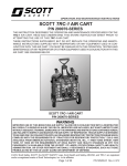
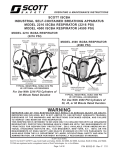
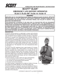
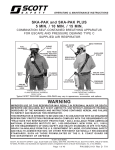
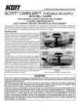
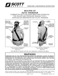
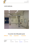
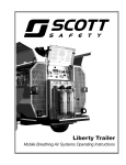
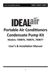
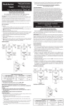
OPERATION AND MAINTENANCE INSTRUCTIONS
SCOTT MOBILE AIR SUPPLY CART
P/N 805825-SERIES, 805826-SERIES, 805827-SERIES
THIS INSTRUCTION DESCRIBES THE OPERATION AND MAINTENANCE PROCEDURES FOR THE
MOBILE AIR SUPPLY CART. READ AND UNDERSTAND THIS ENTIRE INSTRUCTION SHEET PRIOR TO
ATTEMPTING THE USE OF THIS MOBILE AIR SUPPLY CART.
THESE INSTRUCTIONS SUPPLEMENT, BUT DO NOT REPLACE THE OPERATING AND MAINTENANCE
INSTRUCTIONS SUPPLIED WITH RESPIRATORS OR ANY EQUIPMENT USED IN CONJUNCTION
WITH THIS AIR SUPPLY CART. YOU MUST BE FAMILIAR WITH THE OPERATION, TESTING AND
MAINTENANCE OF ANY RESPIRATOR OR OTHER EQUIPMENT USED IN CONJUNCTION WITH THIS
AIR SUPPLY CART.
END-OF-SERVICE
ALARM WHISTLE
HIGH PRESSURE
INLET
RESPIRATOR OUTLETS
(4 OUTLET SHOWN)
TOOL SUPPLY
(P/N 805827-SERIES
ONLY)
WARNING
IMPROPER USE OF THIS BREATHING AIR SUPPLY ALONE OR IN CONJUNCTION WITH A RESPIRATOR
MAY RESULT IN SERIOUS INJURY OR DEATH. IMPROPER USE INCLUDES, BUT IS NOT LIMITED TO USE
WITHOUT ADEQUATE TRAINING, DISREGARD OF THE WARNINGS AND INSTRUCTIONS CONTAINED HEREIN,
AND FAILURE TO INSPECT AND MAINTAIN THE AIR SUPPLY OR RESPIRATOR. THIS AIR SUPPLY IS INTENDED
TO BE USED ONLY IN CONJUNCTION WITH AN ORGANIZED RESPIRATORY PROTECTION PROGRAM WHICH
COMPLIES WITH THE REQUIREMENTS OF “PRACTICES FOR RESPIRATORY PROTECTION,” Z.88.2-1992
AVAILABLE FROM AMERICAN NATIONAL STANDARDS INSTITUTE, INC., 11 WEST 42ND STREET, NEW
YORK, NY 10036 OR THE REQUIREMENTS OF OSHA SAFETY AND HEALTH STANDARD 29 CFR 1910
PARAGRAPH 134 AVAILABLE FROM THE US DEPT. OF LABOR, OCCUPATIONAL SAFETY AND HEALTH
ADMINISTRATION, OR OTHER PERTINENT NATIONALLY RECOGNIZED STANDARDS, SUCH AS THOSE
PROMULGATED BY THE US COAST GUARD OR DEPARTMENT OF DEFENSE.
© 2012 Scott Safety. SCOTT, the SCOTT SAFETY Logo, Scott Health and Safety, and AIR-PAK are registered and/or
unregistered marks of Scott Technologies, Inc. or its affiliates.
Page 1 of 16
P/N 595270-01 Rev. A 6/12
GENERAL DESCRIPTION
The SCOTT Mobile Air Supply Cart can be used as a breathing air supply
for up to four respirators that have an operating pressure range that can be
maintained by this unit, such as the SCOTT AIR-PAK 2.2, 4.5, or 5.5 respirator
or Industrial SCBA equipped with extended duration hose line option, or Type
C air line respirators when used with combination Type C/Escape respirators
such as the SCOTT SKA-PAK respirator.
The Mobile Air Supply Cart is available in configurations as follows:
• 805825-SERIES
Two outlet breathing RESPIRATOR SUPPLY
• 805826-SERIES
Four outlet breathing RESPIRATOR SUPPLY
• 805827-SERIES
Four outlet breathing RESPIRATOR SUPPLY with
a separate Two outlet TOOL SUPPLY to supply up
to two air powered tools.
The Mobile Air Supply Cart can be fitted with two cylinders filled with clean
breathing air. The two cylinders may be either 2216 psi, 3000 psi, 4500 psi,
5500 psi, or any combination of these. The minimum NIOSH duration of any
cylinder shall be thirty (30) minutes. All units are fitted with a high pressure
inlet which permits connection of the Mobile Air Supply Cart to a remote
high pressure breathing air source for continuous service while saving the
cylinders as reserve.
The Mobile Air Supply Cart consists of a wheeled frame unit containing the
air supply cylinders with all controls. The cart handle extends to facilitate
transport. Each cylinder supply connection has its own vent valve, allowing
replacement of one cylinder while the other is in use. An inlet high pressure
gauge on the high pressure manifold and low pressure gauges on the installed
low pressure manifolds indicate the pressure at each stage of the system.
A low pressure warning alarm whistle indicates, along with the supply pressure
gauge, when the selected cylinder supply is low or when the high pressure
breathing air source has dropped to approximately 500 psi.
The standard RESPIRATOR SUPPLY outlets have an adjustable regulated
outlet pressure between 0 and 100 psi as indicated by the outlet pressure
gauge. The outlets are available in a number of quick disconnect configurations to match the various respirator air lines available from SCOTT. When
installed, the separate TOOL SUPPLY has a dedicated pressure regulator
and supplies up to two air powered tools.
MOBILE AIR SUPPLY CART
OPERATION AND USE GUIDELINES
The operation instructions contained herein are intended only as guidelines.
It is intended that an organized respiratory protection program be used in
conjunction with this Mobile Air Supply Cart .
When the Mobile Air Supply Cart is supplying air to respirators, its operation
and air supply must be monitored by an attendant. The attendant monitoring
the Mobile Air Supply Cart must be familiar with the operation of the Mobile
Air Supply Cart and all instructions in this document and must insure that
replacement cylinders are available.
The attendant monitoring the Mobile Air Supply Cart must be ready to
switch to the unused cylinder supply when the selected cylinder supply has
reached the low cylinder point, the low cylinder warning alarm has been
activated, or there is an indication on the supply pressure gauge that the
supply pressure (whether from a cylinder or from a remote high pressure
supply source) is low whether the alarm has gone off or not. After switching
to the unused cylinder, the used cylinder should be immediately replaced
with a fresh fully charged cylinder.
P/N 595270-01 Rev. A 6/12
Page 2 of 16
If a replacement cylinder is not available, the respirator users must be
recalled from the hazardous environment until additional air supplies
can be obtained or the cylinders on hand can be recharged. The attendant monitoring the air supply must have a means of communicating
with the respirator users. Use of a two way communication system is
recommended.
SERVICE LIFE
Each size of breathing air cylinder for use with a self-contained breathing
apparatus (SCBA) is certified by NIOSH and assigned a “service life” classification for a duration time (30 minute, 45 minute, etc.). The service life
duration time of each cylinder is determined by NIOSH using a breathing
machine designed to simulate an average adult respirator user performing
work at a “moderate work rate.”
This Mobile Air Supply Cart is to be used with two breathing air cylinders each
with a minimum duration of 30 minutes. Do not expect to obtain the NIOSH
rated service life duration time from any one cylinder. When used to supply
breathing air to respirator users, the work being performed may be more or
less strenuous than that used in the NIOSH test. Where work is more strenuous, the duration may be less than one half the NIOSH rated service life. The
end of service indicator alarm actuates when approximately 500 psi pressure
remains in the cylinder and valve assembly regardless of the total pressure
of the cylinder when full. This does not necessarily correspond to the NIOSH
requirement for an end of service indicator alarm that notifies the user of one
quarter (25%) of the total cylinder capacity remaining. The end of service
indicator alarm will continue to operate until the cylinder is nearly depleted.
The duration time of the respirator will depend on such factors as:
WARNING
ACTUATION OF THE END OF SERVICE INDICATOR ALARM WARNS THAT APPROXIMATELY 500 PSI REMAINS IN THE AIR SUPPLY CYLINDER THAT IS CURRENTLY IN USE
OR THAT THE REMOTE HIGH PRESSURE AIR
SUPPLY HAS DROPPED BELOW APPROXIMATELY 500 PSI. AFTER ALARM ACTUATION, A DELAY IN CORRECTING THE PROBLEM OR IN NOTIFYING THE RESPIRATOR
USERS TO LEAVE THE AREA MAY RESULT
IN SERIOUS INJURY OR DEATH.
1. the degree of physical activity of the user;
2. the physical condition of the user;
3. the degree to which the user’s breathing is affected by emotional
factors;
4. the degree of training or experience which the user has with this
or similar equipment;
5. loose or improperly fitting facepiece;
6. the condition of the respirator.
7. whether or not the cylinder is fully charged at the start of the work
period;
8. the possible presence in the compressed air of carbon dioxide
concentrations greater than .04% normally found in atmospheric
air;
9. the atmospheric pressure; for example, if used in a pressurized
tunnel or caisson at 2 atmospheres (15 psi gauge or approximately
30 psi absolute) the duration will be one-half as long as when
used at 1 atmosphere; and at 3 atmospheres will be one-third as
long;
10.the additional use of the air supply to power pneumatic tools.
See the OPERATION AND USE GUIDELINES section of this instruction for more information.
QUESTIONS OR CONCERNS
If you have any questions or concerns regarding use of this equipment, contact
your authorized SCOTT distributor, or contact SCOTT at 1-800-247-7257 (or
704-291-8300 outside the continental United States).
Page 3 of 16
P/N 595270-01 Rev. A 6/12
AIR SUPPLY REQUIREMENTS
It is the responsibility of the organized respiratory protection program
under which this unit is used to provide a source of air that is clean
and safe for breathing and to ensure that all other requirements of the
breathing air supply system stated herein are met.
The compressed air cylinders or hose line supply feeding the Mobile Air Supply Cart must contain or supply breathing air meeting
the requirements of the Compressed Gas Association, Inc. (CGA)
Commodity Specification for Breathing Air, G-7.1, grade D or better, available from the CGA, Inc., 1235 Jefferson Davis Highway,
Arlington, Virginia 22202. In addition to meeting the requirements
of Grade D or higher, the air must be dry to a dew point of -65° F
(-54° C) or less. See SCOTT Specialist Level Maintenance Manual
available upon request from SCOTT for additional information on
refilling SCOTT breathing air cylinders.
NOTE
IF THE MOBILE AIR SUPPLY CART IS USED TO SUPPLY AIR
FOR AIR TOOLS, THE AIR SUPPLY MUST STILL BE MAINTAINED TO THE ABOVE STANDARD. LUBRICATION FOR THE
AIR TOOLS MUST BE ADDED AFTER THE MOBILE AIR SUPPLY
CART OUTLETS TO PREVENT CONTAMINATION OF THE AIR
PATHS OR DAMAGE TO INTERNAL SEALS WITHIN THE MOBILE
AIR SUPPLY CART. HOSES USED FOR TOOL SUPPLY MUST
BE CLEARLY IDENTIFIED AND NEVER USED FOR SUPPLY OF
BREATHING AIR.
The two cylinders may be either 2216 psi, 3000 psi, 4500 psi, 5500
psi, or any combination of these. The minimum NIOSH duration of any
cylinder shall be thirty (30) minutes.
Check the latest cylinder hydrostatic test date to ensure it is current.
All cylinders used with SCOTT Mobile Air Supply Cart must be visually
inspected and hydrostatically tested by a licensed cylinder retester in
accordance with the appropriate US Department of Transportation
(DOT) specification or the applicable DOT exemption. For a complete listing of retest date requirements, refer to the current revision
of Safety Precautions for Air-Pak Cylinders, SCOTT P/N 89080-01,
available on request from SCOTT Safety. Composite cylinders (those
cylinders utilizing fiber over wrap) must be tested in accordance with
the DOT exemption status up to the maximum life of fiber overwrapped
cylinders which, at the time of the publication of this instruction, is 15
years from the date of manufacture. The date of manufacture marked
on the cylinder is also the date of the first hydrostatic test. Undamaged
Aluminum and Steel cylinders may be used indefinitely with regular
retesting. It is the responsibility of your organized respiratory protection program to arrange for visual inspection and hydrostatic testing
of cylinders by a licensed retester.
P/N 595270-01 Rev. A 6/12
Page 4 of 16
WARNING
DO NOT USE OXYGEN OR CONTAMINATED “SHOP” AIR SUPPLIES TO FEED THE
SCOTT MOBILE AIR SUPPLY CART. USE
ONLY BREATHING AIR FOR HUMAN RESPIRATION (CGA SPECIFICATION G-7.1, GRADE
D OR BETTER). USE OF ANYTHING OTHER
THAN BREATHING AIR MAY RESULT IN SERIOUS INJURY OR DEATH.
Visually inspect cylinder for physical damage such as dents or gouges
in metal or in composite wrapping. Cylinders which show physical
damage or exposure to high heat or flame, such as paint turned brown
or black, decals charred or missing, pressure gauge lens melted or
elastomeric bumper distorted, and cylinders which show evidence of
exposure to chemicals such as discoloration, cracks in the cylinder or
the composite wrapping, peeling of the outer layers of the composite
wrapping and/or bulging of the cylinder wall, shall be removed from
service and emptied of compressed air. Refer to current applicable
publications on compressed gas cylinder inspection available from
Compressed Gas Association Inc., 1725 Jefferson Davis Hwy., Suite
1004, Arlington, VA 22202, (703-412-0900) for a detailed explanation
of cylinder inspection procedures.
The SCOTT Mobile Air Supply Cart is to be supplied only with clean
breathing air from the compressed air cylinders or from a high pressure hose line supply. Always start with both cylinders fully charged.
Keep the cylinder valves closed when they are not in use. Always have
enough replacement cylinders to ensure there will be a backup cylinder
available as long as the Mobile Air Supply Cart is in use.
The high pressure inlet will accept a high pressure hose line source
of breathing air of up to 5500 psi. The high pressure hose line must
have a shutoff at the outlet end. When used to supply the Mobile Air
Supply Cart, the high pressure supply of breathing air must have the
same flow capability as a cylinder supply at low pressure ranges down
to approximately 500 psi. The minimum outlet pressures required by
the respirator(s) when the respirator(s) are being breathed on, must be
maintained throughout the range of pressures in the hose line feeding
the Mobile Air Supply Cart at least to a point below the low pressure
supply alarm turn on pressure. The minimum supply hose line pressure
must be established in a clean breathing air area. If the high pressure
hose supply cannot maintain the minimum supply pressure required
by the respirator(s) as shown on the outlet gauge, DO NOT use the
hose line supply to feed the Mobile Air Supply Cart.
Two fully charged cylinders, one in the LEFT position and one in the
RIGHT position should be kept as backup to the high pressure hose
line supply.
NOTE
THE HIGH PRESSURE SUPPLY CANNOT BE USED TO RECHARGE
THE INSTALLED CYLINDERS. THE MOBILE AIR SUPPLY CART IS
EQUIPPED WITH CHECK VALVES TO ISOLATE AND PROTECT
EACH OF THE CYLINDERS AND THE HIGH PRESSURE SUPPLY
INPUT. USE OF A HIGH PRESSURE HOSE SUPPLY THAT IS RATED
HIGHER THAN THE INSTALLED CYLINDERS WILL NOT AFFECT
THE CYLINDERS.
Page 5 of 16
P/N 595270-01 Rev. A 6/12
AIR CYLINDER INSTALLATION
1. Inspect the cylinders to be installed in accordance with the AIR
SUPPLY REQUIREMENTS section of this instruction.
2. Set the RESPIRATOR OUTLET PRESSURE REGULATOR control
knob to the full counterclockwise (decrease pressure) position.
3. On one side of the main frame assembly, open the cylinder retention strap fully by releasing the strap buckle and pulling it open to
its widest setting.
4. Place a fully charged cylinder in the frame with the valve assembly
at the top and with the air outlet fitting pointing toward the high
pressure hose connection.
5. Hold the cylinder in place while pulling the end of the strap through
the buckle until the strap is tight around the cylinder. The straps
are equipped with hook-and-loop fasteners to secure the excess
strap material. See FIGURE 2.
WARNING
CYLINDER
STRAP
BUCKLE
SECURE END
OF STRAP
USE ONLY BREATHING AIR CYLINDERS
WHICH ARE RETAINED SECURELY BY THE
RETENTION STRAPS. DO NOT USE CYLINDERS WHICH ARE EITHER TOO SMALL OR
TOO LARGE FOR THE RETENTION STRAPS.
IF A SECURE FIT CANNOT BE ACHIEVED, DO
NOT USE THE CYLINDER. USE OF IMPROPERLY FITTING CYLINDERS MAY RESULT IN
DAMAGE TO THE CYLINDER, CYLINDER
VALVE, OR HOSES WHICH COULD CAUSE
SERIOUS INJURY OR DEATH.
FIGURE 2
CYLINDER INSTALLATION
6. Check that the vent valve is closed, turned fully clockwise and tight.
Do not overtighten. See FIGURE 3.
HIGH PRESSURE
COUPLING
GASKET
VENT
VALVE
FIGURE 3
VENT VALVE
FIGURE 4
HIGH PRESSURE
COUPLING GASKET
7. Inspect the high pressure coupling to be certain the coupling gasket
is present and undamaged. See FIGURE 4. If the gasket is present
and undamaged, align the high pressure coupling with the outlet
of the cylinder valve and hand tighten the coupling to the cylinder
valve. Hand tighten only.
8. Repeat the Steps 1 through 7 above to install the second air cylinder.
P/N 595270-01 Rev. A 6/12
Page 6 of 16
CAUTION
WRENCHES SHALL NOT BE USED TO TIGHTEN THE HOSE COUPLING. OVER TIGHTENING THE HOSE COUPLING MAY DAMAGE
THE COUPLING GASKET.
REGULAR OPERATIONAL INSPECTION
The following procedure shall be used when you first receive the Mobile
Air Supply Cart and prior to use with any other type of equipment. If
damage or discrepancies are noted during the inspection of the unit,
remove it from service and tag for repair by authorized personnel.
This procedure will consume air from both cylinders. A breathing air
supply with shutoff valves or cylinders of at least 2000 psi may be
used for this test. Cylinders used for testing must be replaced with full
cylinders after testing or the cylinders must be topped off prior to use
of the Mobile Air Supply Cart.
1. Visually inspect the unit for completeness, making sure the
graphics and warning labels are readable.
2. Inspect the wheeled cart frame for damaged parts or loose
hardware.
3. Inspect the valve outlet threads on each cylinder.
4. Inspect the Vent Valves for each cylinder. Vent Valves shall remain
captive when screwed out (counterclockwise) and seat firmly when
screwed in (clockwise).
5. The unit can now be fitted with cylinders or connected to a supply
of air as described above. Inspect the high pressure coupling to
be certain the coupling gasket is present and undamaged. See
FIGURE 4. If the gasket is present and undamaged, align the high
pressure coupling with the outlet of the cylinder valve and tighten
the coupling to the cylinder valve by hand. Hand tighten only.
6. Ensure that both cylinder valves are closed (push in and rotate the
cylinder valve knob fully clockwise).
7. Check all RESPIRATOR outlet connections for dirt or contamination.
Clean as required. Care must be taken to remove any dirt accumulations or obstructions from the couplings. Do not allow anything to
become lodged within the coupling. See FIGURE 5.
RESPIRATOR
OUTLETS
WARNING
IF DAMAGE OR DISCREPANCIES ARE NOTED DURING THE REGULAR OPERATIONAL
INSPECTION OF THE UNIT, REMOVE IT
FROM SERVICE AND TAG FOR REPAIR BY
AUTHORIZED PERSONNEL. USE OF EQUIPMENT THAT DOES NOT PASS THE REGULAR
OPERATIONAL INSPECTION MAY RESULT IN
SERIOUS INJURY OR DEATH.
CAUTION
WRENCHES SHALL NOT BE USED TO TIGHTEN THE HOSE COUPLING. OVER TIGHTENING THE HOSE COUPLING MAY DAMAGE
THE COUPLING GASKET.
RESPIRATOR
OUTLETS
FIGURE 5
RESPIRATOR OUTLETS
(FOUR OUTLET VERSION SHOWN)
Page 7 of 16
P/N 595270-01 Rev. A 6/12
9. On units with the TOOL SUPPLY, check both outlet connections
for dirt or contamination. Clean as required. Care must be taken to
remove any dirt accumulations or obstructions from the couplings.
Do not allow anything to become lodged within the coupling. See
FIGURE 6.
TOOL SUPPLY
OUTLETS
FIGURE 6
OPTIONAL TOOL OUTLETS P/N 805827-SERIES
10.Verify that the RESPIRATOR OUTLET PRESSURE REGULATOR is turned fully counter clockwise (set to the lowest possible
setting).
RESPIRATOR INLET
PRESSURE GAUGE
RESPIRATOR
OUTLET PRESSURE
REGULATOR
RESPIRATOR
OUTLET PRESSURE
GAUGE
FIGURE 7
RESPIRATOR OUTLET PRESSURE REGULATOR
NOTE
ALWAYS TURN THE RESPIRATOR OUTLET PRESSURE REGULATOR FULLY COUNTERCLOCKWISE TO THE LOWEST POSSIBLE SETTING BEFORE CHARGING THE SYSTEM WITH HIGH
PRESSURE. CHARGING THE SYSTEM WITH HIGH PRESSURE
WHILE THE RESPIRATOR OUTLET PRESSURE REGULATOR IS
NOT TURNED FULLY COUNTER CLOCKWISE WILL CAUSE THE
MANIFOLD RELIEF VALVE TO OPEN WITH A LOUD “POP”. IF THIS
HAPPENS, SIMPLY CLOSE THE CYLINDER OR HIGH PRESSURE
SUPPLY AND FULLY CLOSE THE REGULATOR.
P/N 595270-01 Rev. A 6/12
Page 8 of 16
11.Test the operation of the low pressure warning alarm with each of
the cylinder supplies and, when installed, the high pressure supply
as follows:
a) Slowly open the cylinder valve or supply valve allowing the
pressure indication on the RESPIRATOR INLET PRESSURE GAUGE to slowly increase to the full supply pressure.
The low pressure warning alarm whistle shall actuate momentarily until the supply pressure increases beyond 1000
psi. See FIGURE 7.
NOTE
IF THE LOW PRESSURE WARNING ALARM DOES NOT ACTUATE
OR THE REGULATED PRESSURE IS OUTSIDE THE INDICATED
PRESSURE RANGE, REMOVE THE UNIT FROM SERVICE AND
TAG FOR REPAIR BY AUTHORIZED PERSONNEL.
b) Turn the RESPIRATOR OUTLET PRESSURE REGULATOR
clockwise until the RESPIRATOR OUTLET pressure gauge
reads between 60 and 100 psi for use with SCOTT respirators.
Refer to the Operation and Maintenance instructions provided
with other respirators for manufacturer’s recommendations.
c) When installed, turn the TOOL SUPPLY REGULATOR clockwise until the TOOL OUTLET pressure gauge reads the desired
output pressure.
NOTE
THE TOOL OUTLET PRESSURE CAN BE LESS BUT CAN NEVER
BE MORE THAN THE RESPIRATOR OUTLET PRESSURE.
d) Check that the outlet configurations match those on the equipment intended to be used with this air supply. There are many
different types of disconnects and some are similar. Test each
outlet with a short length of hose line intended to be used with
this unit, by connecting it to each of the outlets making sure that it
is firmly connected and shows no leakage around the fittings.
e) Close the selected cylinder valve. Vent the trapped air in the
Mobile Air Supply Cart by partially engaging a male quick disconnect plug into one of the RESPIRATOR OUTLET couplings.
As the high pressure gauge reading drops, the low pressure
warning alarm whistle shall actuate at approximately 500 psi
and continue as the system is vented.
f) After testing, turn the RESPIRATOR OUTLET PRESSURE
REGULATOR fully counterclockwise (set to the lowest possible
pressure setting).
12.The supply of air for this test can now be removed. After disconnecting the air supply (either cylinder or remote high pressure line) there
may be air pressure trapped within the system. Use a short length
of air hose fitted with a male quick disconnect on one end to vent
a RESPIRATOR outlet, and, if installed, a TOOL SUPPLY outlet.
Verify that all pressure gauges are reading “zero” when done.
13.If the unit is to be stored with cylinders in place, install two fully
charged cylinders of either 2216 psi, 3000 psi, 4500 psi, 5500 psi,
or any combination of two pressures, or recharge the test cylinders
to the full condition prior to use. The minimum NIOSH duration of
any cylinder shall be thirty (30) minutes. Refer to the CYLINDER
CHARGING PROCEDURE section of the SCOTT SPECIALIST
LEVEL MAINTENANCE MANUAL.
Page 9 of 16
WARNING
IF THE LOW PRESSURE WARNING ALARM
DOES NOT ACTUATE. TAKE THE UNIT OUT
OF SERVICE AND TAG FOR REPAIR BY AUTHORIZED PERSONNEL. USE OF EQUIPMENT THAT DOES NOT PERFORM AS SPECIFIED MAY RESULT IN SERIOUS INJURY OR
DEATH.
WARNING
DO NOT STAND DIRECTLY IN FRONT OF
THE AIR FLOW WHILE VENTING RESIDUAL
PRESSURE FROM THE SYSTEM. THE RUSH
OF HIGH PRESSURE AIR MAY CAUSE SERIOUS INJURY.
P/N 595270-01 Rev. A 6/12
NORMAL OPERATION
USING THE MOBILE AIR SUPPLY CART TO SUPPLY AIR
TO RESPIRATORS
The SCOTT Mobile Air Supply Cart, when properly configured, can
be used as the breathing air supply for up to four extended duration
respirators such as the SCOTT AIR-PAK 2.2, 4.5, or 5.5 respirator
with extended duration option, for Type C respirators such as SCOTT
hose line respirators or combination Type C/Escape respirators such
as the SCOTT SKA-PAK respirator within the operating pressure range
that can be maintained by this unit. Refer to the Users Instructions for
the respirator for complete information about the use of the respirator
with a remote breathing air supply.
1. When the Mobile Air Supply Cart is being used to supply respirators with breathing air, an attendant must monitor the cart at all
times. This attendant must be provided with a means of alerting
the respirator users (such as an air horn or similar device) in case
of a problem with the air supply. Use of a two way communication
system is recommended. See OPERATION AND USE GUIDELINES on page 3 of this instruction.
2. Set up the Mobile Air Supply Cart with the proper air supply. See the
AIR SUPPLY REQUIREMENTS section of this instruction sheet.
a) Install two fully charged breathing air supply cylinders as
instructed in the AIR CYLINDER INSTALLATION section of
this instruction.
b) Provide sufficient additional fully charged air cylinders to supply
the requirements of the application.
c) When available, connect the High Pressure Inlet to a remote
high pressure breathing air supply.
3. Move the Mobile Air Supply Cart to the use position as prescribed
in your respiratory protection program. The Mobile Air Supply Cart
can be rolled into position by tipping it backwards onto the wheels.
Adjust the handle to a comfortable height with the handle lock
screw. The Mobile Air Supply Cart must only be moved when it is
not being used to supply breathing air.
4. When in the use, the Mobile Air Supply Cart should be located on
a firm flat surface.Stand the Mobile Air Supply Cart upright for
easy access to the cylinder valves and controls
5. Refer to TABLE 1 for Limitations and Operating Instructions
for the various hoses used to supply respirators. Refer to
FIGURE 8 to identify the hose connectors available. There
are specific restrictions regarding maximum length and/or
number of hose segments that may be used to supply breathing air to respirators.
P/N 595270-01 Rev. A 6/12
Page 10 of 16
WARNING
DO NOT USE THE MOBILE AIR SUPPLY CART
TO SUPPLY RESPIRATORS USED IN IDLH
(IMMEDIATELY DANGEROUS TO LIFE AND
HEALTH) ATMOSPHERES UNLESS THOSE
RESPIRATORS ARE EQUIPPED WITH AN
EMERGENCY BACKUP AIR SUPPLY OF SUFFICIENT DURATION TO PERMIT ESCAPE
FROM THE IDLH ATMOSPHERE. FAILURE TO
PROVIDE EMERGENCY BACKUP AIR SUPPLY IN SUCH SITUATIONS MAY RESULT IN
SERIOUS INJURY OR DEATH.
WARNING
THE MOBILE AIR SUPPLY CART MUST BE
MONITORED BY AN ATTENDANT WHILE
RESPIRATORS ARE BEING SUPPLIED WITH
BREATHING AIR. THE ATTENDANT MUST
HAVE A MEANS OF ALERTING THE RESPIRATOR USERS OF A PROBLEM WITH THE AIR
SUPPLY. USE OF A TWO WAY COMMUNICATION SYSTEM IS RECOMMENDED. FAILURE
TO PROVIDE A PROPERLY TRAINED AND
EQUIPPED ATTENDANT AT THE MOBILE AIR
SUPPLY CART MAY RESULT IN SERIOUS
INJURY OR DEATH TO THE RESPIRATOR
USERS.
WARNING
THE NORMAL DURATION TIMES OF STANDARD BREATHING AIR CYLINDERS CANNOT
BE EXPECTED WHEN SUPPLYING MULTIPLE
USERS FROM THE MOBILE AIR SUPPLY
CART. PROVIDING MULTIPLE RESPIRATORS WITH BREATHING AIR MAY QUICKLY
DEPLETE THE AIR SUPPLIED BY CYLINDERS ALONE. THIS PROBLEM WILL BE
MAGNIFIED WHEN USING HOSE LENGTHS
GREATER THAN ONE HUNDRED FEET OR
WHEN USING AIR POWERED TOOLS. A
“SIXTY MINUTE” CYLINDER UNDER HEAVY
USAGE MAY BE DEPLETED IN AS LITTLE
AS FIVE MINUTES OR LESS. FAILURE TO
PROVIDE SUFFICIENT AIR RESERVES FOR
THE SITUATION WHERE THE MOBILE AIR
SUPPLY CART IS BEING USED MAY RESULT
IN SERIOUS INJURY OR DEATH TO THE RESPIRATOR USERS.
WARNING
IF THIS EQUIPMENT DOES NOT PERFORM
AS DESCRIBED, REMOVE THE UNIT FROM
SERVICE AND TAG FOR REPAIR BY AUTHORIZED PERSONNEL. USE OF EQUIPMENT
THAT DOES NOT OPERATE PROPERLY MAY
RESULT IN SERIOUS INJURY OR DEATH.
WARNING
THE USER OF THIS RESPIRATOR MAY HAVE TO DISCONNECT THE HOSE COUPLING SUDDENLY AND UNDER
STRESSFUL CONDITIONS. THE USER MUST BE ABLE TO DISCONNECT THE COUPLING UNDER THE CONDITIONS WHICH MAY BE ENCOUNTERED DURING USE, FOR EXAMPLE, WITHOUT BEING ABLE TO SEE THE
COUPLING, WITH GLOVES ON, WITH ONE HAND, ETC. FAILURE OF THE USER TO ADEQUATELY PERFORM
THESE TASKS UNDER STRESSFUL CONDITIONS MAY RESULT IN SERIOUS INJURY OR DEATH.
TABLE 1
LIMITATIONS AND OPERATING INSTRUCTIONS FOR SUPPLY HOSE
NOTE: THE AIR SUPPLY PRESSURE MUST BE MAINTAINED BETWEEN 60 PSIG AND 100 PSIG
WHILE FLOWING AT LEAST 200 LITERS PER MINUTE (LPM) TO EACH USER.
Approved
Total
Lengths (ft)2
Supply Hose1
26369 Series
with stainless steel
Hansen HK
couplings
0 to 150
63
26370 Series with
stainless steel Foster
couplings
0 to 300
123
30010 Series with
brass Hansen couplings
0 to 300
123
30020 Series with
steel Schrader couplings
805659 Series with
brass CEJN couplings
1
2
3
Maximum Number
of Segments
Approved3
0 to 300
1. To connect the coupling, rotate socket sleeve “B” until
the alignment notch in the sleeve is in line with alignment peg in body “A”.
2. Slide sleeve “B” toward the supply hose (away from plug
“C”) and insert plug “C” into socket “A”. Release sleeve
“B” while pushing the plug into the socket until engaged,
as evidenced by a “click”. Test for positive engagement
by tugging on the plug.
3. Rotate sleeve “B” one-quarter to one-half turn to lock
the plug against accidental release.
4. To disconnect the coupling, realign sleeve “B” with the
body of socket “A” as described in step 1. Slide sleeve
“B” away from the body (toward the supply hose) to
release the plug fitting from the socket.
IF IT IS NOT PRACTICAL TO SEE THE ALIGNMENT
NOTCH IN THE SLEEVE, USE THE FOLLOWING
PROCEDURE TO DISCONNECT THE COUPLING:
1. Grasp sleeve “B” with the right hand.
2. Simultaneously rotate and push the sleeve away from the
plug until the alignment notch in the sleeve lines up with
the alignment peg in the body and the socket separates
from the plug.
1. Insert plug fitting “C” into socket “A” and continue
pushing until it is engaged as evidenced by a “click”.
2. Test for positive engagement by tugging on the plug.
3. Disconnect the coupling by rotating sleeve “B” 1/8
turn in the clockwise direction as viewed from the
female end of socket “A”.
123
0 to 300
INSTRUCTIONS FOR OPERATION OF COUPLINGS
Note: The user shall practice and be able to disconnect the couplings quickly in an emergency situation.
1. Insert plug fitting “C” into socket “A” and continue
pushing until it is engaged as evidenced by a “click”.
2. Test for positive engagement by tugging on the plug.
3. Disconnect the coupling by pushing in on plug “C” while
pulling back on sleeve “B”. Plug “C” will separate.
123
The female connectors on all supply hose series are checked to stop the flow of air when they are disconnected. Both male and
female connectors are checked on 26369 series supply hose.
“0” feet = direct connection to air supply source.
Segments of supply hose are commonly available in 25 ft, 50 ft, 75 ft, and 100 ft length segments.
A
B
C
HANSEN HK COUPLING
USED ON 26369
SERIES
A
B
C
FOSTER COUPLING
USED ON 26370
SERIES
A
B
C
SCHRADER COUPLING
USED ON 30020
SERIES
A
B
C
A B
C
HANSEN COUPLING USED CEJN COUPLING USED
ON 30010 SERIES
ON 805659 SERIES
FIGURE 8
COUPLINGS USED ON SUPPLY HOSES
Page 11 of 16
P/N 595270-01 Rev. A 6/12
6. If the Mobile Air Supply Cart is being used with air cylinders only,
begin use as follows:
a) Check that both cylinder gauges indicate full and their valve
are closed.
b) Verify that both Vent Valves are closed.
c) Verify that the RESPIRATOR OUTLET PRESSURE REGULATOR is turned fully counterclockwise (set to the lowest possible
setting).
d) Select either the LEFT or RIGHT cylinder. Slowly open the
cylinder valve allowing the pressure indication on the inlet
pressure gauge to slowly increase to the full cylinder pressure. The low pressure warning alarm whistle shall actuate
momentarily until the supply pressure increases beyond 1000
psi. Open the cylinder valve completely by turning valve knob
fully counterclockwise.
e) Turn the RESPIRATOR OUTLET PRESSURE REGULATOR
clockwise until it indicates a pressure of 60 to 100 psi with no
respirator(s) attached. There shall be no sound of air flow or
leakage.
7. If the Mobile Air Supply Cart is being used with both remote high
pressure breathing air supply and air cylinders begin use as
follows:
a) Check that both cylinder gauges indicate full and that their
valves are closed.
b) Verify that both Vent Valves are closed.
c) Verify that the remote high pressure breathing air supply is
attached to the high pressure inlet.
d) Verify that the RESPIRATOR OUTLET PRESSURE REGULATOR is turned fully counterclockwise (set to the lowest possible
setting).
e) Slowly open the high pressure supply valve allowing the pressure indication on the inlet pressure gauge to slowly increase
to the full supply pressure. The low pressure warning alarm
whistle shall actuate momentarily until the inlet supply pressure
increases beyond 1000 psi.
f)Turn the RESPIRATOR OUTLET PRESSURE REGULATOR
clockwise until it indicates a pressure of 60 to 100 psi with no
respirator(s) attached for use with SCOTT respirators. Refer
to the Operation and Maintenance instructions provided with
other respirators for manufacturer’s recommendations. There
shall be no sound of air flow or leakage.
8. The Mobile Air Supply Cart is now ready to supply respirators with
breathing air. Connect each hose line to one of the RESPIRATOR
outlets. Refer to the Operating and Maintenance Instructions for
the respirator to verify the following:
a) Make sure the couplings are compatible between the respirator
and the Mobile Air Supply Cart.
b) Make sure the couplings are operated properly. See TABLE 1
and FIGURE 8.
P/N 595270-01 Rev. A 6/12
Page 12 of 16
WARNING
IF THIS EQUIPMENT DOES NOT PERFORM
AS DESCRIBED, REMOVE THE UNIT FROM
SERVICE AND TAG FOR REPAIR BY AUTHORIZED PERSONNEL. USE OF EQUIPMENT
THAT DOES NOT OPERATE PROPERLY MAY
RESULT IN SERIOUS INJURY OR DEATH.
c) Perform the respirator REGULAR OPERATIONAL INSPECTION as detailed in the Operation and Maintenance instructions
for the respirator being used.
NOTE
THE OUTLET PRESSURE MUST NOT GO BELOW THE MINIMUM REQUIRED BY THE RESPIRATOR(S). THE ABILITY OF
THE AIR SUPPLY TO PROVIDE THE REQUIRED AIR PRESSURE
TO RESPIRATORS WHILE IN USE, MUST BE CONFIRMED IN A
CLEAN BREATHING AIR AREA. REFER TO THE MINIMUM AND
MAXIMUM AIR PRESSURE REQUIREMENTS SPECIFIED IN THE
USER INSTRUCTIONS FOR THE RESPIRATOR.
9. If the low pressure warning alarm sounds or the inlet pressure
gauge indicates a low supply pressure and the Mobile Air Supply
Cart is being used with air cylinders only, switch to the unused
cylinder as follows:
a) Open the cylinder valve on the unused cylinder.
b) When the inlet supply pressure rises above 1000 psi, the alarm
shall reset itself. The outlet gauge pressure must return to the
operating level as stated above.
NOTE
THE LOW PRESSURE WARNING ALARM CANNOT BE SILENCED.
IF THE SYSTEM PRESSURE IS NOT RESTORED TO ABOVE 1000
PSI, THE ALARM WILL CONTINUE TO SOUND UNTIL ALL AIR IS
DEPLETED FROM THE SELECTED CYLINDER.
c) Fully close the valve on the used cylinder by pushing the knob
in and turning clockwise.
d) Vent the line to the used cylinder by slightly opening the vent
valve.
e) When the venting is complete, immediately replace the used
cylinder with a fully charged cylinder in that position by removing
the high pressure coupling from the valve of the used cylinder.
Open the cylinder strap and remove the used cylinder.
f) Place a fully charged cylinder into this position orienting the
valve outlet so the high pressure coupling can be attached.
Check for the presence of the coupling gasket and that it is
properly seated. Tighten the coupling to the cylinder outlet using hand tight pressure only. Hand tighten only. See the AIR
CYLINDER INSTALLATION section of this instruction.
10. If the low pressure warning alarm whistle sounds or the inlet pressure gauge indicates a low inlet pressure from the remote high
pressure breathing air supply and the Mobile Air Supply Cart is
being used with both remote high pressure breathing air supply
and air cylinders, switch to the cylinder supply as follows:
a) Fully open one of the cylinder valves.
b) When the inlet pressure rises above 1000 psi, the alarm shall
reset itself. The outlet gauge pressure must return to the operating level as stated above.
c) Fully close the valve on the High Pressure supply hose.
d) Continue use as stated above for use with air cylinders only.
Page 13 of 16
WARNING
THE OUTLET PRESSURE MUST NOT GO
BELOW THE MINIMUM REQUIRED BY THE
RESPIRATORS. MORE RESPIRATOR USERS
AND LONGER SUPPLY HOSE LENGTHS MAY
REQUIRE A HIGHER OUTLET PRESSURE
SETTING TO MAINTAIN THE AIR SUPPLY
TO ALL USERS. THIS MUST BE CHECKED
OUT IN A CLEAN BREATHING AIR AREA.
FAILURE TO PROVIDE SUFFICIENT AIR
PRESSURE TO SUPPLY THE RESPIRATORS
MAY RESULT IN SERIOUS INJURY OR DEATH
TO THE RESPIRATOR USERS.
WARNING
IF THIS EQUIPMENT DOES NOT PERFORM
AS DESCRIBED, REMOVE THE UNIT FROM
SERVICE AND TAG FOR REPAIR BY AUTHORIZED PERSONNEL. USE OF EQUIPMENT
THAT DOES NOT OPERATE PROPERLY MAY
RESULT IN SERIOUS INJURY OR DEATH.
P/N 595270-01 Rev. A 6/12
USING THE MOBILE AIR SUPPLY CART
TO SUPPLY PNEUMATIC TOOLS
1. The Mobile Air Supply Cart may be equipped with optional separate TOOL SUPPLY outlets to provide air to operate a variety of
pneumatic devices. The TOOL SUPPLY has an adjustable regulator that can be set to any output pressure equal to or less than the
RESPIRATOR OUTLET PRESSURE REGULATOR. The TOOL
SUPPLY is fitted with two outlets.
2. The Mobile Air Supply Cart must only be supplied with clean
breathing air, see section on AIR SUPPLY REQUIREMENTS.
When using the Mobile Air Supply Cart to supply air to pneumatic
devices other than respirators, care must be taken not to
contaminate the RESPIRATOR circuit of the Mobile Air Supply
Cart. Any lubrication added for air tools must be added after
the TOOL SUPPLY outlet. Hoses which are intended to supply
air for respiratory protection must not be used to supply air for
other purposes. Hoses used to supply air to tools must be clearly
identified as not for respiratory use.
3. Test to be sure the Mobile Air Supply Cart will maintain the minimum
outlet pressure needed for the desired air tool to run properly. If
the Mobile Air Supply Cart can not maintain the required pressure, DO NOT use it to operate the tool. Damage or injury may
result from operating some pneumatic tools without the proper
supply pressure.
4. If any of the hoses used to supply pneumatic tools have an inside
diameter which exceeds 1/2-inch (12.7 mm), those hoses must be
equipped with a safety device to reduce pressure in case of hose
failure according to OSHA Standard 29 CFR 1926. It is the user’s
responsibility to provide the safety device.
P/N 595270-01 Rev. A 6/12
Page 14 of 16
WARNING
USE OF AIR TOOLS WILL QUICKLY CONSUME THE AIR PROVIDED BY AIR CYLINDERS ALONE. OPERATORS OF THE MOBILE
AIR SUPPLY CART MUST TAKE PRECAUTIONS TO PREVENT DANGER TO RESPIRATOR USERS FROM SUDDEN DEPLETION
OF THE AIR SUPPLY. USING AIR TOOLS
WHILE SUPPLYING BREATHING AIR TO RESPIRATOR USERS MAY CAUSE A SUDDEN
DEPLETION OF THE AIR SUPPLY AND MAY
RESULT IN SERIOUS INJURY OR DEATH TO
THE RESPIRATOR USERS.
WARNING
TOOLS MUST BE CONNECTED ONLY TO THE
TOOL SUPPLY OUTLETS. NEVER CONNECT
TOOLS TO THE RESPIRATOR OUTLETS.
CONTAMINATION FROM TOOL LUBRICANTS
TO THE BREATHING AIR SUPPLY FROM THE
RESPIRATOR OUTLETS MAY RESULT LEADING TO SERIOUS INJURY OR DEATH OF
RESPIRATOR USERS.
TERMINATION OF USE
To discontinue use of the Mobile Air Supply Cart proceed as follows:
1. Verify that respiratory protection users of the Mobile Air Supply
Cart are clear of the area requiring respiratory protection.
2. Users must have doffed (removed) their respiratory protection
equipment and disconnected their air supply lines from the Mobile
Air Supply Cart.
3. Fully close both air cylinders. Push in and turn the cylinder valve
knobs clockwise to close.
4. When used, close the valve on the High Pressure supply hose and
disconnect the remote high pressure breathing air source from the
High Pressure Inlet.
5. Slowly open each of the two vent valves to vent remaining pressure
in the system.
6. Vent the trapped air in the Mobile Air Supply Cart by partially
engaging a Male Quick Disconnect plug into one of the RESPIRATOR OUTLET couplings
7. Close the RESPIRATOR OUTLET PRESSURE REGULATOR
and, if installed, the TOOL SUPPLY REGULATOR by turning fully
counterclockwise (set to the lowest possible setting).
8. Remove Mobile Air Supply Cart to a safe area and perform procedures as indicated in MAINTENANCE section of this instruction.
WARNING
DO NOT STAND DIRECTLY OVER THE VENT
VALVES WHILE VENTING. WHEN VENTING,
HIGH PRESSURE AIR ESCAPES FROM THE
VENT HOLE. THAT RUSH OF HIGH PRESSURE AIR MAY CAUSE SERIOUS INJURY.
MAINTENANCE
No attempt shall be made to replace components or to make adjustments or repairs beyond the scope of this instruction manual without
proper training.
1. Clean and inspect the Mobile Air Supply Cart after use.
2. Damp sponge dirt accumulations from the cart, cylinders, and fittings. Use care so as not to deface or damage the warnings and
instructions printed on the Mobile Air Supply Cart.
3. After cleaning perform the REGULAR OPERATIONAL INSPECTION as described in this manual.
4. Install fully charged air cylinders as directed in AIR CYLINDER
INSTALLATION section of this instruction.
5. Store the Mobile Air Supply Cart in a cool dry area after use.
6. If any damage or deterioration is noted during cleaning and inspection, remove the Mobile Air Supply Cart from service and tag it for
repair by authorized personnel.
7. Prior to storing away any respirator used with the Mobile Air Supply Cart, clean and inspect it by following the MAINTENANCE
or MAINTENANCE AND CLEANING procedure contained in the
instruction manual supplied with each respirator.
Page 15 of 16
WARNING
I F D A M A G E O R D I S C R E PA N C I E S A R E
FOUND DURING THE REGULAR OPERATIONAL INSPECTION, REMOVE THE UNIT
FROM SERVICE AND TAG FOR REPAIR BY
AUTHORIZED PERSONNEL. USE OF EQUIPMENT THAT DOES NOT PASS THE REGULAR
OPERATIONAL INSPECTION MAY RESULT IN
SERIOUS INJURY OR DEATH.
P/N 595270-01 Rev. A 6/12
SCOTT SAFETY
Monroe Corporate Center
PO Box 569
Monroe, NC 28111
Telephone 1-800-247-7257
Fax (704) 291-8330
www.scottsafety.com
Printed in USA
P/N 595270-01 Rev. A 6/12
Page 16 of 16