1
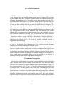
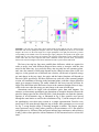
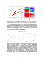
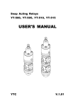
DESIREE – A Double Electrostatic Storage
Ring for Merged-Beam Experiments
H. Danared*, L. Liljeby*, G. Andler*, L. Bagge*, M. Blom*, A. Källberg*,
S. Leontein*, P. Löfgren*, A. Paál*, K.-G. Rensfelt*, A. Simonsson*,
H. T. Schmidt†, H. Cederquist†, M. Larsson†, S. Rosén† and K. Schmidt†
*
Manne Siegbahn Laboratory, Frescativägen 28, S-104 05 Stockholm, Sweden
Department of Physics, Stockholm Universtity, S-106 91 Stockholm, Sweden.
†
Abstract. DESIREE is a double electrostatic storage ring cooled to cryogenic temperatures. It is
built at the Manne Siegbahn Laboratory for merged-beam and single-beam experiments in
atomic and molecular physics as well as biophysics. This paper describes the present status of
the design of DESIREE.
Keywords: Storage rings, electrostatic rings, merged beams, ion-ion collisions
PACS: 29.27.-a, 41.75.-i, 82.30.Fi
INTRODUCTION
Electrostatic storage rings were introduced [1] a little less than a ten years ago as a
tool for studies in atomic and molecular physics and related disciplines. Since then,
several other electrostatic rings have been or are being built, and yet others are being
planned. At the Manne Siegbahn Laboratory, a double electrostatic storage ring,
DESIREE [2], is being designed, as reported in this paper.
There are several reasons for building electrostatic rather than magnetic storage
rings when high particle energies are not required. Perhaps the most important factor,
at least in the present case, is cost. An electrostatic bending element, such as a pair of
deflection plates, is much cheaper to manufacture than a dipole magnet. It is also
lighter and smaller, allowing a more compact design of the ring (or rings) as a whole.
Another factor, often quoted, is that the electrical force is stronger than the
magnetic force for low particle velocities, since the magnetic force is proportional to
the velocity. As a result, heavy particles in low charge states can have higher
velocities in electrostatic rings than in magnetic ones. Assuming electrical field
strengths similar to those in the existing electrostatic rings and magnetic fields similar
to those in small magnetic storage rings like CRYRING, one finds a cross-over at a
mass of about 100 for singly charged ions. Heavier particles will move faster in an
electrostatic ring and vice versa. Whether high particle velocities is an advantage is
another issue, and the answer depends on what type of experiments one wants to
perform.
A third advantage is that, for an ion source on a given electrical potential, ions with
all charge-to-mass ratios can be stored in an electrostatic ring without change of the
CP821 Beam Cooling and Related Topics, International Workshop on Beam Cooling and Related Topic - COOL05
edited by S. Nagaitsev and R. J. Pasquinelli
© 2006 American Institute of Physics 0-7354-0314-7/06/$23.00
465
voltages of the ion-optical elements. The charge-to-mass ratio used in the ring is then
selected by an analyzing magnet in the injection line. The ring can thus be set up with
an ion species where a high current is available, and a second species can then be
stored by just changing the setting of the analyzing magnet, even if the current is too
low for the available ring diagnostics.
Some difficulties in building electrostatic storage rings are due to the fact that there
exists less experience from such devices, and there are fewer design tools available.
Also, electrostatic beam-optical elements tend to have larger aberrations than magnetic
ones.
DESIREE (Double ElectroStatic Ion Ring ExpEriment), see fig. 1, is a double
electrostatic ring designed for experiments with merged beams of positive and
negative ions. It can also be used for experiments with only one ring, such as
measurement of atomic lifetimes or studies of the physical properties of biomolecules.
The entire device will be cooled to a temperature of 5–8 K in order to achieve a good
vacuum and allow the storage of molecular ions in their lowest vibrational and
rotational states.
FIGURE 1. Schematic diagram of DESIREE with the lids of the vacuum vessels removed.
The fact that DESIREE will be cooled to cryogenic temperatures motivates the use
of electrostatic technology, since the device then can be made sufficiently compact so
that both rings can be built inside a single cryostat, as seen in the figure.
DESIREE is now being designed, and construction of the main components will
begin during 2006. It is expected that commissioning can start at the end of 2007.
466
TECHNICAL DESIGN
Rings
DESIREE consists of two rings, each one with a circumference of approximately
9.3 m. The rings have one common straight section where the beams of the two rings
are merged. Both rings have 160-degree cylindrical bends and 10-degree parallel-plate
deflectors. The upper ring in fig. 1 (referred to as the light-ion ring) always has a 10degree deflection at the ends of the common straight section. The lower ring (the
heavy-ion ring) can have ions with different energy or charge compared to the lightion ring, and these will then deflect by an angle that is different from 10 degrees. Due
to geometric constraints, the ions in the two rings must have charges with opposite
sign, and the deflection angle at the end of the straight section can range between 0.5
and 10 degrees for ions in the heavy-ion ring. Additional deflectors are required in this
ring to compensate for the varying deflection angle. All deflecting and bending
elements have a focussing action in the horizontal plane, and, in addition, there are
four quadrupole doublets in each ring and a few horizontal and vertical correction
elements.
Injection is made by a rapid switching of the respective 10-degree deflectors. A
settling time of 1 µs is foreseen for the deflector voltage supply, which will be
sufficient for the injection of H+ or H- at 100 kV. Possibly, extraction will also be
implemented in a similar way.
The rings are designed for a maximum energy of 100 keV times the charge state of
the ion, i.e., for injection from a platform on 100 kV. In this case, the maximum
voltage on the electrodes of the optical elements is 16 kV.
An additional geometric constraint is due to the fact that neutral reaction products
from the common straight section must be able to reach detectors located at the
extension of this section, rather than being intercepted by deflection plates. It will also
be possible to detect neutral particles produced on the two injection straight sections.
Since both optical elements and detectors are mounted directly on the bottom of the
inner vacuum vessel, as described below, it will be possible to put detectors in
additional positions if there will be experiments requiring these.
Vacuum and Cryogenics
The two rings will be housed in a common vacuum chamber/cryostat with double
walls. The outer wall or vacuum chamber will be built from 5 mm thick steel, and it
will have to be reinforced by external beams to support the atmospheric pressure. Its
size is approximately 4.9 m × 2.6 m × 0.7 m plus reinforcement beams which add
0.24 m on all sides. The inner chamber will be made from 5 mm aluminium, but it will
have a thicker bottom on which optical elements and detectors will be mounted as
mentioned below. It will have less reinforcements, and it will not be built to withstand
atmospheric pressure. Between the two vessels, there will be a thermal screen and
multilayer insulation between the screen and the outer vessel. The vessels will have
large lids, almost as large as the vacuum vessels themselves. Feedthroughs will mainly
467
be mounted at the bottom of the vessels, such that the lids can be opened without the
need to disconnect all feedthroughs.
The cooling will be achieved through the use of cryogenerators. According to
calculations, two cryogenerators (Sumitomo CSW71/RDK-515D) will be needed to
reach the desired temperature. The first stage of the cryogenerators will be connected
to the screen, and the second stage to the inner vacuum vessel. It is estimated that the
heat load on the screen will be approximately 60 W, which will result in a temperature
below 60 K. The inner vessel will receive a heat load of around 3 W, which should
give a temperature of 5 K on the rings. If the heat loads will become bigger, it is
possible to add one or two more cryogenerators.
It will also be possible to run DESIREE at higher temperatures, up to room
temperature. The inner vacuum vessel thus has to be bakeable to 150ºC, putting
restrictions on the choice of materials, etc. It is then also necessary to have a high
pumping capacity on the inner vessel. This will be achieved through titanium
sublimation pumps in combination with turbo pumps, and it is expected that a pressure
of 1×10-11 mbar can be reached at room temperature. At low temperatures, these
pumps will remove hydrogen and helium while all other gases have negligible vapour
pressure at 5 K.
Fig. 2 shows results of tests of a cryogenerator of the above model. These tests
were made in order to verify the specifications from the manufacturer and to measure
the cooling power at higher temperatures than given in the specifications. It can be
seen from the figure that the agreement between measurements and specifications is
very good in the range where specifications exist.
FIGURE 2. Measurements of temperatures on the first and second stage of a Sumitomo CSW71/RDK515D cryogenerator when a heat load is applied to the second stage. The curves show measurements
and the filled circles represent specifications.
An efficient heat transfer from all components seen by the beams to the
cryogenerators is important in order to get reasonably short cooldown times and low
final temperatures. For this reason, and also for the sake of mechanical stability, the
468
bottom of the inner vacuum vessel will be made from 12 mm thick aluminium, and the
beam-optical elements, detectors, etc., will be mounted directly on this aluminium
plate. Flexible copper braids will connect this plate to the cryogenerator heads. Tests
have indicated that a temperature difference between the aluminium plate and the
cryogenerator head lower than 1 K can be obtained.
Injectors
DESIREE will be provided with at least two injectors, one for each ring, although
both injectors will be able to supply ions to both rings. The injectors consist of a highvoltage platform, an ion source and an analyzing magnet. The injector mainly
supplying the heavy-ion ring will be tailored to heavier ions in that it will be built for a
higher platform voltage, 100 kV, and it will have a larger magnet with higher
resolving power. The magnet itself, with a bending power of 1.9 Tm, will be on earth
potential, but the vacuum chamber will be insulated for 100 kV. The injector mainly
used for the light-ion ring will have a 25 kV platform voltage.
Several kinds of ion sources are foreseen, such as a standard plasmatron (‘Nielsen’
type) source for singly charged atomic and molecular ions, an expansion source for
molecules in low rotational states, an electron-impact source producing molecules in
known vibrational states, a sputter ion source for negative ions, an electrospray source
for complex molecules and biomolecules, and possibly an ECR ion source for
multiply charged ions. The use of a cooled ion trap after the electrospray source is
being investigated. With such a trap the ions can be accumulated and buffer-gas
cooled in order to increase the particle intensity in the beam pulse and to decrease the
beam emittance.
ION OPTICS
The light-ion ring has two symmetry planes, and if the voltages on the ion-optical
elements are to obey that symmetry, the optics is defined by only two parameters: the
focusing and defocusing quadrupole voltages. Using standard linear transfer matrices
for ideal quadrupoles and cylindrical deflectors, and approximating the parallel-plate
deflectors also with cylindrical deflectors, a stability diagram like the one in fig. 3 is
obtained simply from matrix multiplication and standard procedures for calculating
the stability criterion and Q values.
It is seen that the stable islands are relatively small, but that it is possible to find
several working points with, e.g., round well-focused beams in the common straight
section. The smallness of the islands is related to the rather long straight sections
without focusing, which is an inevitable consequence of the merged-beams design.
The existence of stable orbits was initially proven using COSY INFINITY [3], and
later on also with SIMION [4]. The latter code evaluates the electric fields numerically
and in this sense gives more realistic results, at the expense of much longer execution
times, so that much less detail can be obtained. The results from both the COSY
INFINITY and SIMION calculations agree well with those from the simple matrix
multiplications discussed here.
469
FIGURE 3. The left part of the figure shows stable islands for the light-ion ring as a function of the
horizontal and vertical quadrupole strengths (where the strength multiplied by the 0.10 m electrode
length is the inverse of the focal length for a single quadrupole). The right part shows the Q values
corresponding to the islands to the left, and the upper right Q diagram corresponds to the upper right
islands and vice versa. The colours are such that red represents round beams on the common straight
section while blue and violet represent flat beams. Saturated colours represent small, well-focused
beams in the common straight section while unsaturated colours represent unfocused beams.
The heavy-ion ring has four more parallel-plate deflectors, which are required in
order to merge ions with different charge-to-mass ratios or energies with the ions
stored in the other ring. As a result, the heavy-ion ring only has one symmetry plane,
and, since the amount of deflection depends on the charge-to-mass ratios in the two
rings (or, in the general case of different ion velocities, on the ratio of particle energy
per unit charge in the two rings), the optics and the lattice functions will depend on
this ratio. More specifically, the three deflectors on each side of the common straight
section will contribute to focusing in the horizontal plane, such that a larger deflection
angle gives stronger focusing. The stable islands for the heavy-ion ring will thus be
larger if the deflection in the deflectors closest to the common straight section is large,
which is the case when the energy per unit charge is the same in both rings.
Aberrations tend to be larger with electrostatic optics than with magnets. For
instance, an electrostatic quadrupole gets aberrations of octupole character because the
particles change speed in the electrical fields. Such aberrations can limit the dynamic
aperture of an electrostatic ring, as illustrated in fig. 4. Here, particles were traced
through the same lattice as used for the calculations of fig. 3, but the octupole effect of
the quadrupoles were taken into account in a simple approximation. Particles were
traced up to 100 turns through light-ion ring with the same parameters as were used
for fig. 3, except that the range of focusing strengths is smaller. The largest, purple
areas represent k and Q values where particles with an emittance of 0.1 mm mrad in
each plane survive 100 turns. Blue and green indicate larger emittances, and red shows
k and Q values where particles with an emittance of 100 mm mrad survive at least 100
turns.
470
FIGURE 4. The different colours show k and Q values where particles with different emittances
survive at least 100 turns in the light-ion ring. Purple indicates survival of particles with 0.1 mm mrad,
and the emittance increases in steps of 10 mm mrad up to 100.1 mm mrad which is indicated with red.
Fig. 4 is not an exact representation of the dynamic aperture in DESIREE since
aberrations in the deflecting elements are not included, nor higher-order effects in the
quadrupoles. Also, fringe fields are not included. A complete result again requires a
more realistic evaluation of the fields, using a code like SIMION. Such calculations
have been performed for DESIREE, although a map as detailed in fig. 4 would be far
too time-consuming to produce using such a technique.
APPLICATIONS
As mentioned above several plans exist for the use of DESIREE in single-ring
configuration for lifetime measurements and interactions with laser fields ranging
from high-precision spectroscopy with continuous wave lasers to experiments
involving ultra-short pulses in the fs range. However, as the single most original
feature of DESIREE is the possibility to investigate interactions between positive and
negative ions at low relative velocity, we will focus on this aspect here.
The process of mutual neutralization (MN) between two singly charged – one
positive and one negative – ions to form two neutral products is an ideal case for
DESIREE. The neutral products will continue straight in the field where the two ion
beams are separated and can readily be detected. By applying a detector with multihit
capability and position sensitivity it is even possible to determine the amount of
kinetic energy released in the process. Another advantage of such a scheme will be the
direct detection of more than two neutral fragments in coincidence. This is of
importance when molecular ions are taking part in the collisions and the question of
whether the electron transfer is accompanied by dissociation is addressed. The study
of molecular ions will further benefit from one of the other advanced DESIREE
features namely the very low temperature, which in turn leads to very good vacuum
and presumably thereby also very long storage lifetimes. This combination means that
471
infrared-active ions will be found to reach internal temperatures of similarly low
values, thus resulting in population of only one or a few quantum states.
The interest in the MN process is both in the fundamental mechanisms and in total
cross section determinations for related fields such as the chemistry of interstellar
clouds and in planetary atmospheres (including our own). As an example of the
fundamental interest we mention the fact that it is a matter of current debate whether
or not the neutral hydrogen molecule formed in the MN of H- with H2+ (or HD+) will
dissociate [5]. An even simpler system to consider is the p-H- system. Here the
obvious objection to performing such an experiment in DESIREE would be that no
use is made of the low temperatures and the beam storage. This is, however, exactly
the point. In the near future we will engage in an effort to measure this process in a
single-pass merged-beams experiment lead by Prof. Urbain of the Catholique
University of Louvain-la-Neuve in Belgium. The later repetition of the exact same
experiment in DESIREE is expected to provide very useful calibration information
needed for the determination of absolute cross sections for mutual neutralization and
other merged-beams experiments involving molecular ions.
REFERENCES
1. S. P. Møller, Nucl. Instr. Meth. A 394, 281 (1997).
2. K.-G. Rensfelt et al., in Proc. EPAC 2004, edited by J. Poole, J. Chrin, Ch. Petit-Jean-Genaz, C. Prior and H.A. Synal, Lucerne 2004, p. 1425.
3. M. Berz, COSY INFINTY Version 8.1 User’s Guide and Reference Manual, Michigan State Univ. 2002.
4. D. A. Dahl, SIMION 3D Version 7.0 User’s Manual, INEEL, Idaho Falls, USA.
5. M. J. J. Eerden et al., Phys. Rev. A 51, 3362 (1995).
472