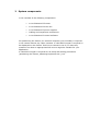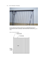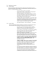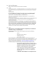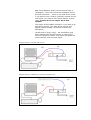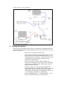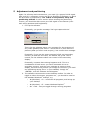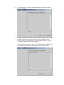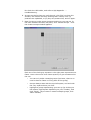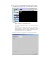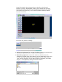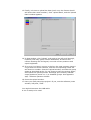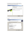
1
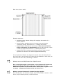
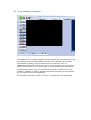
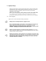
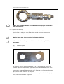
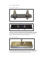
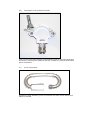
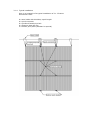
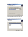
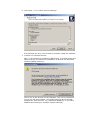
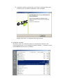
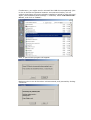
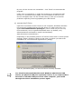
Phantom II Frame
Operator’s Manual
Useful G-Lec phone numbers:G-Lec Europe GmbH
Sales and service*
Service out of hours*
Fax
Email
Website
Distribution:
G-Lec America
Sales and service*
Fax
*Before contacting G-Lec for service enquiry please ensure that you have the
product serial number and the Software version.
The latest version of this manual (in Microsoft® Word® or PDF format) and
G-Lec Software can be downloaded from the website
The small print :
No Liability for Consequential Damages
G-Lec has a policy of continuous product and documentation improvement. As such the detail
within this manual may not match the operation of the product this manual describes.
In no event shall G-Lec be liable for any direct, indirect, special, incidental, or consequential
damages or loss whatsoever (including, without limitation, damages for loss of profits,
business interruption, or other pecuniary loss) arising out of the use or inability to use the
product this manual describes even if G-Lec has been advised of the possibility of such
damages. Because some jurisdictions do not allow the exclusion or limitation of liability for
consequential or incidental damages, the above limitation may not apply to you.
$$$ G-Lec® is a registered Trademark of G-Lec Europe GmbH.
$$$ Patents pending:
Microsoft® and Windows® are registered trademarks of Microsoft Corporation.
Folsom ImagePro…$$$
Reprint and revision history:
Phantom2_quick_manual.pdf – a very brief Quick Start Guide
First, unfinished, preliminary version – for internal cross-check
sb Okt 2006
sb June 2007
1
SAFETY PRECAUTIONS
4
2
SYSTEM COMPONENTS
5
2.1
G-Lec Phantom II frames
2.2
G-Lec Phantom II drive box
2.3
G-Lec Phantom II power supply
2.4
Cabling and suspension accessories
2.5
G-Lec Phantom II software
3
SYSTEM SETUP
6
8
9
12
13
14
3.1
Frame Rigging
3.1.1
Rigging points and load constraints
3.1.2
Quicklock operation
3.1.3
Useful accessories
3.1.4
Typical installation
3.2
PSUs and drive box
3.3
Cabling the frames
3.3.1
power cables
3.3.2
signal cables
3.3.3
cabling example
3.4
DVI and USB cabling
3.4.1
USB
3.4.2
DVI
4
TESTING THE SYSTEM
14
15
16
17
21
22
23
23
23
24
25
25
25
27
5
ADJUSTMENT AND POSITIONING
28
APPENDIX A – SOFTWARE INSTALLATION
36
a) Get the Software
b) Hardware requirements
c)
Software installation
d) software uninstall
e) connect the S-Drive
APPENDIX B – SOFTWARE OPERATION DETAILS
36
36
36
41
43
44
APPENDIX C – GROUP SETUP QUESTIONS
45
APPENDIX D – POWER CALCULATION
46
APPENDIX E – DVI DETAILS
47
APPENDIX F – PLANNING CUSTOM-MADE ANIMATIONS
48
APPENDIX G – TROUBLESHOOTING
49
APPENDIX H – TECHNICAL DATAALPHABETICAL INDEX
50
ALPHABETICAL INDEX
51
1
Safety precautions
G-Lec Phantom II is a very safe and stable system when handled properly.
However, it’s the user’s duty to avoid any dangers or hazards. That’s why
Read – and understand - the manual first!
When in doubt, do not use any devices which might cause harm or
injury to other people!
Do not attempt to use any devices, cables or accessories which
seem to be broken, damaged or otherwise not in original state.
Do not attempt to open, fix or repair anything inside G-Lec devices
without explicit permission by G-Lec. There are absolutely no userserviceable parts inside.
The following potential hazards are typical for situations where G-Lec is
used, and appropriate precautions are to be taken by the operator:
•
Frames, accessories and cables are hung from above, and
hence things might fall down.
•
Power supplies and drive boxes run from mains voltage.
Opening, or the use of wrong or damaged cables, or
connection to improper mains feed may cause electric shock,
serious injury or death. Always use proper original cables
and a correctly installed and earthed mains feed.
•
Frames run from 48 volts, and precautions against voltage
at the housing by fault are taken. Whereas this voltage is
regarded as safe almost all around the world (check your
local regulations), it might shock or otherwise disturb
sensitive people. Do not open frames or cables, do not run
cables in water, and never touch any contacts.
•
Cables, especially in dark stage situations, may cause trip
hazards. Avoid trip hazards by running cables cleanly away
from exits and runways. Use mats, and fix cables with tape,
cable ties etc.
•
LED technology outputs bright light, and quick and fast
flashes can be achieved (depending on your content).
Flashing may cause harm to people suffering from epilepsy,
or otherwise sensitive. Use the system carefully, and
(depending on your local regulations) warn your audience
and workers. Avoid looking directly into LEDs from short
distance.
2
System components
G-Lec consists of the following components:
•
G-Lec Phantom II frames
•
G-Lec Phantom II drive box
•
G-Lec Phantom II power supplies
•
Cabling and suspension accessories
•
G-Lec Phantom II control software
For positioning the frames, an external computer (not included) is required.
G-Lec comes without any video contents. A valid DVI-D-signal is required to
be displayed on the frames. Feel free to contact G-Lec if you have any
questions on what an appropriate DVI-source might be suitable for your
application.
A valid DVI-D-signal is required for all setup and testing procedures
(positioning the frames, adjusting brightness etc.), too.
2.1 G-Lec Phantom II frames
A G-Lec phantom II frame consists of a very lightweight aluminium
structure which houses electronic parts and holds 16 translucent
polycarbonate tubes, which again house small PCBs actually holding the
LEDs.
Front view (not to scale):
Rear view (not to scale):
Function overview:
•
Quicklock male, female: fittings for hanging. See section 3.1 Frame Rigging.
•
Power In/Out: speakon NL4, 48 V, power input and output
(internally linked). See section 3.3 - Cabling the frames.
•
Signal In/Out: fiberoptic SC connectors. These are not linked.
Input and Output are designated! Input is rear-top-left, output
is rear-top-right. See section 3.3 - Cabling the frames.
•
Signal Fault LED: indicates signal fault, turns off when normal
operation is resumed. See section $$$Troubleshooting.
G-Lec Phantom II frames are shipped in special cases: 6 frames fit into
one ‘half’ case. Two of these ‘half’ cases can be attached to each other, to
have one ‘full-size’ case, containing 12 frames.
Always store and ship frames in original cases!
Due to the lightweight construction, G-Lec Phantom II frames are
fragile and require handling with care. Furthermore, G-Lec
Phantom II frames do not stand stable. Never lean it against walls
or cases – always put frames not in use into a box!
Always operate Phantom II-frames hanging upright!
Even though they can hold the weight, they are not built to stand on each
other; they’ll certainly buckle, crash and break.
2.2 G-Lec Phantom II drive box
The G-Lec Phantom II drive box (aka G-Lec Phantom II controller, or
simply BlackBox) converts any DVI-D-signal and sends it via fiberoptic
cables to the frames. Furthermore, it provides a USB-B socket to connect a
computer running the G-Lec Phantom software, used for setting the
frames’ positions and brightness.
Function overview:
•
Power In: mains power intake (110~240 VAC)
•
USB: USB-B 2.0 connector, for connection to your control PC (not
included)
•
Signal Send to frames: the drive box’s signal output
•
Signal Return from frames: the drive box’s signal input (only
required for uploading setup changes)
•
‘Return OK’ LED: indicates properly working return signal
•
‘Power ON’ LED: just the ‘ON’ indicator
•
DVI IN: the signal input. See section 3.4.2 - DVI
•
‘DVI In FAULT’ LED: indicates not present or not valid (wrong
format) DVI input signal
2.3 G-Lec Phantom II power supply
Front view
Rear view
Front view – schematic
Function overview:
•
Channel A ON: push to switch on channel A. Steady green light
indicates channel A being switched on.
•
Channel A OFF: push and hold for appr. 3 seconds to switch off
channel A.
•
Channel B ON: push to switch on channel B. Steady green light
indicates channel B being switched on.
•
Channel B OFF: push and hold for appr. 3 seconds to switch off
channel B.
Do not cover air intake and outlet.
Rear view – schematic
Function overview:
•
Multicore Out: Harting HAN-E connector for long distances. See
section Power for exact instructions and calculations.
•
Output A/B: Speakon NL-4 connectors, 48V output. See section
Power for exact instructions and calculations.
Both speakon outputs and the according multicore output are
paralleled. See section 3.2 - PSUs and drive box - for max.
rating!
As a rule of thumb, the total number of frames per channel must
not exceed 8.
•
Mains Thru: Powercon Mains Output, to daisy chain PSUs using
appropriate cables.
•
Mains In: Powercon Mains Input (120~240 VAC). Use cable with
appropriate connector, meeting your local requirements (obtainable
from G-Lec). See section 3.2 - PSUs and drive box - for rating
considerations. A fully wired PSU with 2 x 8 frames
connected consumes 1800 Watts.
Do not cover air intake and outlet.
2.4 Cabling and suspension accessories
For proper assembling and operation, a bunch of cables and accessories is
required. This includes, but is not limited to
Mains power cables
Speakon power cables
Harting power multicores and adaptors to speakon
Fiberoptic signal cables
Quicklock suspension sets in various combinations
Plates and joint plates, to assemble frame systems
Exact descriptions, calculations and pictures are given in the following
sections respectively.
Always use original G-Lec cables and accessories
Never use broken or otherwise damaged material
2.5 G-Lec Phantom II software
The software CD is initially shipped with the frames and accessories you got;
furthermore it can be downloaded from the G-Lec website. We strongly
recommend to always use the latest version of software. Join our
blackboard/mailing list in order to be up-to-date. Contact your local G-Lec
dealer or the G-Lec tech & service dept. if you need any more information.
A separate Windows®-PC (not included) is required to install and run the
software; software is used to position the frames according to the physical
set-up, and to set overall brightness.
For detailed information, refer to section 5 - Adjustment and positioning.
3
System Setup
Setting up the system involves several work items, which are often done
simultaneously, and usually depend and base on each other. In order to
describe it as exactly as possible, those work items are described
separately in this manual.
Read and understand the entire setup procedure thoroughly first!
E.g. usually you start with basic cabling, then hang the first row(s),
proceed with cabling, add some more rows, do some test, go on cabling…
3.1 Frame Rigging
Again, bear in mind some basic safety precautions:
Always store and ship frames in original cases!
Due to the lightweight construction, G-Lec Phantom II frames are
fragile and require handling with care. Furthermore, G-Lec
Phantom II frames do not stand stable. Never lean it against walls
or cases – always put frames not in use into a box!
Always operate Phantom II-frames hanging upright! Even though
they can hold the weight, they are not built to stand on each other; they’ll
certainly buckle, crash and break.
Always hang frames using original G-Lec quicklock connectors. Any
other kind of suspension, like wire ropes around the housing or the
bottom fixing plate, will most likely damage the frames, and will
void any warranty or liability.
3.1.1 Rigging points and load constraints
The first step is to choose appropriate points to hang the system. Each
frame weighs 6 kg (13 lbs) and is hung at the quicklock connectors.
Hence, the highest load occurs at the very top points.
The quicklocks are safe for hanging 12 frames high (safety factor: 15). In
any case, the rigging points and their supporting structure, as well as all
other suspension kits you may use (e.g. shackles, steels) must be safe for
the double weight, in case one suspension gives way.
Know and obey your local rules regarding safe working load,
handling loads at height/above people, and safety.
System height vs. weight, load, and SWL:
System height
(frame rows)
Weight per
column
Actual load
per point
Required SWL
per point
kg [lbs]
kg [lbs]
kg [lbs]
1
6 [13]
3 [6]
6 [13]
2
12 [26]
6 [13]
12 [26]
3
18 [39]
9 [19]
18 [39]
4
24 [53]
12 [26]
24 [53]
5
30 [66]
15 [33]
30 [66]
6
36 [79]
18 [40]
36 [79]
7
42 [93]
21 [46]
42 [93]
8
48 [106]
24 [53]
48 [106]
9
54 [119]
27 [60]
54 [119]
10
60 [132]
30 [66]
60 [132]
11
66 [146]
33 [73]
66 [146]
12
72 [159]
36 [79]
72 [159]
3.1.2 Quicklock operation
To assemble and lock a quicklock connection:
1. insert the male part straight into the female part
2. firmly push both together, until the safety ring snaps towards the
male part
3. turn the safety ring: the edge hole must not face towards the ball,
in order to prevent accidental unlocking
To unlock and disassemble a quicklock connection:
1. turn the safety ring, so that the edge hole faces towards the ball
2. hold the hung device: it will come free with the next step, and will
fall if not safed
3. pull the safety ring away from the male part
4. the connection will unlock
Quicklocks, loose
Quicklocks, connected yet not secured (safety ring not twisted)
Quicklocks, connected and secured
Make sure both quicklocks of each frame have proper connection
and are secured!
3.1.3 Useful accessories
For a neat installation, G-Lec provides a bunch of useful accessories.
You’re free to add your own ideas which might suit your needs even
better. Contact G-Lec to seek assistance.
Again: know and obey your local safety regulations.
All unauthorized changes to the frames will void any liability or
warranty.
(I)
distance plates
In order to achieve a nice installation, it is of top priority to ensure the
correct distance between two adjoining frames. The best way to do so is
the use of distance plates which are simply put on the quicklock
connectors. Standard distance is 60 mm, whereas for curved surfaces we
do provide other distances on request.
Furthermore we recommend the use of distance plates for the first (top)
row, too, to get a better alignment.
(II)
bottom joint plates
bottom joint plates, standard
Bottom joint plates, special edition (angled)
In order to have equal distances throughout the last/bottom row, the use
of bottom joint plates is recommended. The standard edition will do the
job in most cases, and is perfect for curved setups, while the special
(angled) edition adds stability for straight installations.
(III)
top joint plates
The top joint plate adds stability for the top row (for better alignment) and
reduces the number of required rigging points when used in conjunction
with the appropriate number of female quicklock fittings.
(IV)
halfcoupler with quicklock female
Lets you mount frames directly onto trusses (keep in mind the bracing!)
and tubes, reducing the distance and the number of required steels and
quick connectors.
(V)
quick connectors
Instead of using shackles, quick connectors are often much easier and
faster to handle.
(VI)
sliders and steels
For many situations the perfect way to adjust the height exactly and
quickly – if you have ever used it once, you will never be without again.
Check your local regulations: some venues (at least in germany)
do not allow the use of sliders without separate secondary safety!
3.1.4 Typical installation
Here is an example of a typical installation of 3 x 3 frames.
Accessories used:
6
6
6
6
2
x
x
x
x
x
steel cable with thimbles, equal length!
quick connector
quicklock female/eye bolt
distance plate 60 mm
bottom joint plate (standard or special)
3.2 PSUs and drive box
That’s easy: place the PSUs and the drive box according to your needs. For
the PSUs, it’s a good idea to have it as close as possible to your frames. In
most cases, ‘dimmer city’ will be a good choice, for this is usually where you
get mains from.
The drive box is best placed close to your video source, to have short and
easy cable runs (DVI is limited to 10 meters/30 ft).
For the setup process, it is usually a good idea to have the drive box
together with your setup computer and a video source (likely the DVI output
of the setup computer) close to the frames/on stage. It shouldn’t be too
much hazzle to put it e.g. at F.O.H. later.
Like with all electrical devices, operate PSUs and drive box in dry
environment only, to avoid electrical shock, harm and damage.
Connect the PSUs and drive box to mains, using appropriate cables and
distros if needed.
Total power consumption depends on the number of connected frames. For
safe operation, calculate as follows:
-
you may connect up to 8 frames to each PSU
channel, i.e. 16 frames to each PSU. Total power
consumption should be calculated as 1,800 watts per
PSU (7.8 Amps @ 230 V, or 15 Amps @ 120 V)
-
for a more detailed insight, refer to Appendix $$$ –
power calculation
-
power consumption of the drive box is typically less
than 30 watts
-
PSUs as well as drives boxes are equipped with wide
range switching power supplies: no need to adjust
anything to different voltages when touring the world
3.3 Cabling the frames
3.3.1 power cables
Use 4-pin speakon cables and harting multicores with breakout boxes to
connect the frames with the PSUs. You might daisy-chain the frames (up to
max. 8). In and Out doesn’t matter.
-
keep all cables as short as possible
-
max. cable run PSU – frame when connected with
speakon only must not exceed 20 m
-
for longer distances, use harting multicore. In that
case, the first speakon cable (from breakout box to
first frame) must not exceed 5 m. In any case, the
harting cable must not exceed 50 m.
-
if longer cable runs are necessary, or the daisy chain
link (between adjoining frames) exceeds 1.5 m, you
might encounter flickering when driving the frames
full white @ 100% brightness. Reduce brightness, or
reduce number of frames per PSU channel.
-
See Appendix $$$ - power calculation - for details.
3.3.2 signal cables
Use G-Lec fiberoptic cables (50/125 µm, SC/SC) to loop the signal from
the drive box’s out throughout all frames to the drive box’s in.
-
the order of how the frames are daisy-chained
doesn’t matter, e.g. you could wire by rows or by
columns, or columns top-down or bottom-up
-
when setting up closed walls, the best idea is cabling
by rows (you will only need short jumpers, and
longer cables from one row to the next).
-
Input and Output does matter! Connect the drive
box’s output (send) with your first frame’s input,
then its output with the next input… and finally the
last frame’s output with the drive box’s input (return)
-
A frame’s input is top-right, when looking from
front, or top-left, when looking from rear. Refer
to section 2.1 - G-Lec Phantom II frames - for
schematic drawings.
-
‘First’ and ‘last’, when used in context of the frames
or signal, always refers to the signal flow, and hence
the order in which you cabled your frames. Even
though the order doesn’t matter as for general
functionality, systematic cabling is highly
recommended in order to avoid faults and track
errors.
-
You might use standard fiberoptic cables throughout
the entire system, i.e. from the drive box on, through
all frames, back to the drive box. However, for long
runs, esp. from and to the drive box if placed at
F.O.H, the use of heavy duty cables should be
considered. Contact G-Lec if you have any questions.
3.3.3 cabling example
3.4 DVI and USB cabling
Now it’s time to hook up the drive box externally.
3.4.1 USB
As mentioned earlier, a standard Windows® PC is required for system setup
and maintenance (you may disconnect the PC once the system is properly
set up).
Requirements:
PC, running Microsoft® Windows® (actually there are no Windows Vista®
drivers available, even though some users report running the software
under Vista®. Use Windows 2000® or Windows XP®.)
There are no extraordinary hardware requirements – any recent PC or
laptop will do the job.
It’s strongly recommended to install the software on your control PC prior to
connecting the USB link. Follow the instructions in $$$ Appendix B –
Software installation.
After software installation is completed, use a standard USB A-B cable to
connect the drive box to your PC. When connecting to your PC for the first
time (or the first time to a designated USB port, for Windows® administers
those drivers per port separately), the ‘new hardware found’ message will
appear. Follow the instructions and install the drivers which are already
copied to your system while software being installed.
3.4.2 DVI
The presence of a valid DVI-D signal is compulsory for all kinds of
operation, setup, or maintenance.
As of the time of this writing, the DVI signal must meet the following
requirements:
-
DVI-D
-
Resolution: 640 x 480 px
-
Frequency: 60 Hz
-
Color depth: 32 bpp
Sound knowledge of video and DVI should be deemed prerequisites for
proper operation of G-Lec Phantom II. Please refer to $$$ Appendix C – DVI
for a short overview. Furthermore, find some literature or search the web
(highly recommended: Wikipedia - http://en.wikipedia.org/wiki/Dvi)
In order to get you up and running, here are the most common hints:
-
whereas most notebooks/laptops recognize newly
attached DVI displays while running, standard PCs do
recognize it only at boot time. Hence, if you have
problems to activate your DVI output (secondary
display), a reboot might solve your problem
-
if your video source outputs a different format and
cannot be adjusted, you need to use a separate
converter. We highly recommend the $$$Folsom
ImagePro HD
-
a VGA-DVI cable adaptor is a wrong tool for G-
Lec. Such adaptors simply convert VGA to DVI-A
(analogue) – they just connect the analogue pins of
the DVI-connector - , which is not what G-Lec needs
-
if you want to use a control (preview) monitor for the
DVI signal, you need to have a DVI splitter. In that
case, connect G-Lec to output #1 of that
splitter!
-
The length of DVI cables is limited: if you want to go
beyond 10 meters, you need active devices and
special cables (usually: conversion to and from
fiberoptics)
-
Usually DVI is ‘plug-n-play’ – but sometimes, esp.
after changes with the DVI source, a reset of the
drive box might be useful: just unplug the power for
some seconds, and re-power again.
Example hookup 1: DVI and USB from PC
Example hookup 2: USB from PC, DVI from external source
Example hookup 3: using a DVI splitter
4
Testing the system
Now it’s time to perform some checks. It cannot be overemphasized that
quick little checks along with the setup will make your life easier and save
you a lot of time.
-
make sure everything is powered up
-
as soon as the frames are powered up, but lack valid
input signal (either disconnected fiberoptics, or no
valid input to the drive box), a red led on each frame
(underneath the top housing) indicates power
presence and signal fault.
-
At the drive box, two green LEDs should be lit:
‘Power On’ indicating On, and ‘Return OK’ indicating
valid return from the frames. If the latter is off, recheck your signal wires.
-
If DVI-D is properly hooked up and matches the
required format, the red LED ‘DVI In Fault’ should be
off, and the frames should show the DVI-signal.
(Most likely the alignment and positioning will not fit
– but at least you should see something).
-
Refer to $$$ Appendix D – Troubleshooting – if you
have any problems to get it running so far.
5
Adjustment and positioning
Again: for all setup and maintenance, you need (a) a proper DVI-D signal
feed, and (b) a computer running the G-Lec Phantom II software, to which
the drive box is connected by USB. If DVI is not present, setup and
positioning will fail. In other words: before starting the positioning
routine, you should be able to see your DVI signal on the frames (even
with wrong positions and brightness).
1. Fire up the software
Eventually, you get the message ‘Can’t get capture device’
This is for the software scans your computer for the presence of
any video grabber/input device – which fails if no such device is
present (what you don’t need anyway). Just confirm this message.
Eventually, if you use the same computer’s DVI out (secondary
monitor) to feed the drive box, the frames will go off. This is
normal, for the software takes over control of the secondary
display.
Eventually, it seems that nothing happens at all. This is a
combination of both items: you have connected G-Lec as
secondary monitor, and the error message is output to that
display, but due to the position you simply do not see it (you shall
see something saying ‘Error’ in your taskbar). Simply hit
<ENTER>, and the software should appear.
2. The software consumes the entire desktop surface. In order to
toggle to other documents, programs etc., you should be used to
the standard Windows® hotkeys, e.g.
o
(Windows) + D – minimizes all programs, and brings up
your desktop
o
(Windows) + E – starts Windows Explorer®
o
Alt + Tab – lets you toggle through running programs
3. Now, the software should be up and running:
4. In the left pane, click the ‘Get Serial Number’ button. Another
window appears:
5. In that new window, click the ‘detect’ button. Within that window,
a list of all frames will scroll through, saying ‘Sended’ for all
present frames. Simultaneously, the frames will start to show a
1~3 digit number: their serial number.
If you encounter an error saying ‘exit, failed open device (DEV 0),
the software is unable to communicate with your drive box.
Re-check the USB cable, and refer to $$$ Appendix … troubleshooting.
6. As soon as the list has run until the end, click ‘Exit’ to close this
window; the frames will keep showing their number until (a)
positions are uploaded, or (b) they are powered off, and on again.
7. Now it’s time to make some groups according to your set-up. In
the main software window, left pane, click ‘Create Groups’ – and
the Create Groups window appears:
Each one of the little grey squares in the right pane represents one
frame. Hover the mouse over those squares, to get accustomed to
the use.
o
You can only make rectangle groups (but later, there is no
need to have a frame in every place of the group)
o
Groups always start with the top-left square, and end with
the very square where you click.
o
Highlight a group representing your set-up (by clicking on
the bottom-right square depending on your number), and
click ‘Finish’. (If you want to create multiple groups, click
‘Next’ instead).
8. Now, you’re back to the main window, and your newly created
group appears in the center pane, along with a little grey handle:
You can:
o
Select the group by clicking the handle
o
Drag and drop the group’s position, by clicking and dragging
the handle
o
Delete the group: right-click the handle, and click ‘Delete’
o
Edit the group, i.e. insert the frames’ serial numbers, by (a)
double-clicking the handle, or (b) right-clicking the handle,
and selecting ‘Edit’ from the context menu.
The Group Edit window will appear with the group’s properties:
9. Now, every frame of your group is represented by a little white
input field, initially showing ‘0’. Double-click the first field, and
input the number of the appropriate frame. Navigate with the
mouse or <TAB> to the next frame, and fill in the next number.
Repeat this procedure for all your frames
N.B. while typing in the numbers, in the left pane you should see
changes of the ‘Current serial number’, which shows the internal
ID.
Once all numbers are set, click ‘OK’ to close that window and
return to the main program window. By now, all frames in the
center pane should show the numbers you just have input:
10. Next step is to put the group in the correct position. This very
position depends on the physical setup, and on the available video
content. As a rule of thumb, if it’s only one group, a good starting
point is to place it in the center of the screen. If it’s multiple
groups, a good starting point is to set the relative positions
according to the physical setup (e.g. matching distances), while
the position of the entire setup (all groups) should be in the center
of the screen again.
Refer to $$$ Appendix …, Group setup specials, for further
information.
Simply drag and drop the group by its handle to the desired
position. For fine adjustments pixel by pixel, select the group by
clicking the handle, and click the position arrows at the top (each
click moves by one pixel). Hint: use the position readings at the
bottom status bar:
And here the position reading:
11. Adjust the brightness (by moving the fader at the very top with the
mouse) if required (100% is a good starting point)
12. Save the project! As soon as all data are uploaded and the
software is closed, there is no was to get the data back. You’ll have
to redo all steps described. That’s why get into the habit to save
your project regularly. In the main window’s left pane, click ‘Save
Project’ – the appearing dialog should be familiar:
13. Finally, it’s time to upload the data (until now, the frames should
still show their serial number). Click ‘Upload Data’, and the ‘Upload
Data’ window appears:
14. In that window, click ‘Upload’, and again a list will scroll through,
hopefully with only green entries. Meanwhile, all frames will
resume showing the DVI signal, now with correct positions and
equal brightness.
15. If an error (red entry) occurs in the list, the most common issue is
a typo with the serial numbers, and the corresponding frame will
still show its number. Close the Upload window, and edit the group
again as described earlier. Do not forget to save the project again,
and repeat the upload process. Warnings (blue entries) indicate
empty positions (serial no: 0) or disabled groups. See Appendix
$$$ - software operation details.
16. Close the upload window.
17. Have you really saved the project? If yes, exit the software (main
window, left pane, ‘EXIT’.
You might disconnect the USB cable.
G-Lec is ready to be used.
Appendix A – Software Installation
a) Get the Software
Initially, the software is shipped with the G-Lec frames and hardware, or
handed out during the initial training. You can get the software from your
local G-Lec representative or the G-Lec technical or service and support
dept. Please check regularly for updates and changes: G-Lec has a policy of
continuous product and documentation improvement. As such the detail
within this manual may not match the operation of the product this manual
describes, even though we do our best to keep hardware, software, and
documentation up to date.
Furthermore, you might consider joining the G-Lec mailing list, in order to
keep track latest changes and announcements. Contact the service & support
dept. in order to get more information about this.
b) Hardware requirements
The software is quite modest in requirements – any windows based
computer bought in the last four years should suffice. Particularly, you’ll
need:
-
a processor speed of 800 MHz or above
-
min. 1.5 MB HDD space (recommended: 10 MB, to
install some demo animations)
-
min. 128 MB memory installed
-
one USB 2.0 port (USB 1.1 works, too, but is
remarkably slow)
-
if you want to run animations on the same computer:
a DVI-D port with a decent graphic processor
-
display size: min. 1,024x768 px (recommended:
1,280 x 1,024)
c) Software installation
Since the software might install new drivers and codecs, you’ll need
to run the installation with administrative privileges on your
computer.
In order to keep things easy, G-Lec highly recommends to install the
software (and thus the drivers) prior to connecting the S-Drive.
Again: at first install the software, only then connect the S-Drive.
(Refer to $$$ Appendix Troubleshooting if you have problems with that)
1. start the setup.exe (it might have an extended name, like
glec_setup_b2-4_2_4.exe, to distinguish different versions at a
glance). The usual welcome-screens pops up:
2. click ‘Next >’ to see some important information regarding actual
drivers:
3. click ‘Next >’ to select the destination folder:
Click ‘Browse…’ and select a folder of your choice if you want to
change the default setting (<system’s program folder>\G-Lec
Phantom II).
4. click ‘Next >’ to select the components you’d like to install:
Here, you can customize your installation. In the drop-down-menu
you can select between ‘full’ and ‘custom installation’ – when you
install it on a particular computer for the first time, ‘full’ is certainly
the best choice.
The components in a brief:
- program files: the program and some needed components.
Certainly almost necessary
- test movies: some movies, to test colors, positions and alike. Very
useful, but consume most space
- USB drivers: let you computer communicate with the S-Drive box.
Needed only once if you plan to run multiple installations
- codecs: highly recommended. Necessary to show movies from
within the software
Select the components you wish to install.
5. click ‘Next >’, to see the start menu options:
This is to determine how G-Lec will appear in your start menu. Alter
the settings if you wish, and
6. click ‘Next >’ to re-check all your settings:
If all settings are okay, click ‘Install’ to actually install the software.
7. confirm non-windows drivers
Now, if you selected to install the USB drivers, a window might pop
open to inform you about the installation of drivers not Microsoftcertified (WHQL-conform):
This is due to the drivers for the USB port. (Do not be confused if
you do not see this window: you might have this driver already
installed for other devices, e.g. USB-serial adaptors; or you have
disabled this warning in windows’ system settings).
8. installation should go quite fast, and finally a window pops open,
confirming the successful installation of the software:
Simply click finish, to complete the setup process.
d) software uninstall
As always, there are numerous ways to uninstall the software. The
recommended way is to use Windows system settings -> software. Select
‘G-Lec Phantom II’ and click on ‘remove’:
Furthermore, you might need to uninstall the USB drivers separately (this
is due to license and practical reasons: as mentioned earlier, it’s not
unlikely that those drivers are already installed on behalf of other devices).
Again, use windows system settings -> software, select ‘FTDI FTD2XX USB
Drivers’, and click on ‘remove’:
Now, a special little program will appear:
Make sure the G-Lec S-Drive box is disconnected, and proceed by clicking
‘Continue’:
By now, all the drivers are uninstalled – click ‘Finish’ to terminate this
program.
Under rare circumstances, it might be necessary to uninstall the USB
drivers in a somehow forced mode. Do not hesitate to ask the G-Lec
service & support dept. for the FTClean utility in case you encounter
problems regarding removing/updating the USB drivers.
e) connect the S-Drive
Upon first connection of the S-Drive to the computer, Windows activates
the previously installed drivers for this device. In order to do this, you
again need administrative privileges. (This is valid only for the very
first connection, and is a general Windows issue: by default, only
administrators are allowed to install new hardware).
$$$ (other/more screenshots?)
Depending on the possible presence of similar drivers and on some system
settings, again a window is likely to pop open, to inform you about the
installation of a not-Microsoft-signed driver (WHQL):
Click on ‘proceed anyway’, to have the driver correctly installed.
You should understand that Microsoft Windows administers USB
drivers per physical USB port separately. Hence, if you connect the SDrive box to another USB port of the same computer, you’ll walk
through this driver installation process again.
Appendix B – Software Operation Details
Appendix C – Group setup questions
Appendix D – Power calculation
Appendix E – DVI details
Appendix F – Planning custom-made animations
Appendix G – Troubleshooting
Appendix H – Technical Data
Alphabetical Index