1
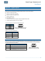
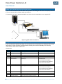
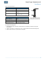
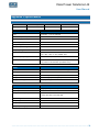
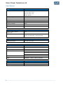
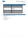
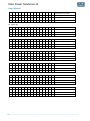
Dale Power Solutions Ltd User Manual E200 Series UPS 3 phase input single phase output E2310(E) E2315E E2320E Dale Power Solutions Ltd Salter Road, Eastfield Industrial Estate, Scarborough, North Yorkshire, YO11 3DU, UK [email protected] | www.dalepowersolutions.com | +44 (0) 1723 583511 S5264FU03 Rev 2 Dale Power Solutions Ltd User Manual User Manual Dale Power Solutions Ltd own the copyright to this document, which may not be copied, reproduced or disclosed to a third party without written permission. Dale Power Solutions Ltd reserves the right to make changes in specification without notice or liability. All information is subject to Dale Power Solutions Ltd own data and is considered accurate at time of publishing. 2 ………………………………………………………………………………………………………… Dale Power Solutions Ltd User Manual User Manual Contents Safety..................................................................................................................................................... 5 EMC .................................................................................................................................................... 5 Warning symbols ................................................................................................................................. 5 Product description .............................................................................................................................. 6 Applications ......................................................................................................................................... 6 Product range ...................................................................................................................................... 6 System block diagram .......................................................................................................................... 7 Features .............................................................................................................................................. 7 Installation............................................................................................................................................. 8 Siting considerations ............................................................................................................................ 8 Wiring considerations ........................................................................................................................... 8 Operation from a generator .................................................................................................................. 9 Circuit breaker and cable sizes............................................................................................................. 9 Unpacking the UPS.............................................................................................................................. 9 Rear panel layout ............................................................................................................................... 10 Wiring the UPS .................................................................................................................................. 11 Wiring units in parallel ........................................................................................................................ 13 Operation..............................................................................................................................................15 Working modes .................................................................................................................................. 15 On-Line mode .............................................................................................................................................. 15 Bypass mode ............................................................................................................................................... 15 Battery mode ................................................................................................................................................ 15 ECO mode ................................................................................................................................................... 15 Before switch on ................................................................................................................................ 16 Switching on the UPS ........................................................................................................................ 16 Switching off the UPS ........................................................................................................................ 16 Swapping out a UPS on a live system ................................................................................................ 17 Front panel controls and indicators ..................................................................................................... 18 Navigating the system menu ......................................................................................................................... 19 Figure menu items ........................................................................................................................................ 19 Status menu items ........................................................................................................................................ 19 Setting menu items ....................................................................................................................................... 20 Command menu items .................................................................................................................................. 21 LCD display messages ................................................................................................................................. 22 Maintenance .........................................................................................................................................23 Fan .................................................................................................................................................... 23 Battery ............................................................................................................................................... 23 External battery change ..................................................................................................................... 23 Visual check....................................................................................................................................... 23 UPS status check ............................................................................................................................... 23 Function check................................................................................................................................... 23 ………………………………………………………………………………………………………… 3 Dale Power Solutions Ltd User Manual User Manual Troubleshooting .................................................................................................................................. 24 Appendix 1 Signals options ................................................................................................................ 25 RS232 serial port ............................................................................................................................... 25 Contact closure (basic monitoring and control) ................................................................................... 25 SNMP card (advanced monitoring and control)................................................................................... 26 Relay card (advanced monitoring and control) .................................................................................... 26 Appendix 2 Parallel board signals ...................................................................................................... 28 LBS (Load Bus Synchronisation) ........................................................................................................ 28 Dry contact relay signals .................................................................................................................... 28 Appendix 3 Specifications................................................................................................................... 29 Electrical ............................................................................................................................................ 29 Mechanical ........................................................................................................................................ 31 Appendix 4 Optional equipment.......................................................................................................... 31 Appendix 5 UPS alarm tables .............................................................................................................. 32 4 ………………………………………………………………………………………………………… Dale Power Solutions Ltd User Manual User Manual Safety WARNING! THIS EQUIPMENT MUST BE INSTALLED, COMMISSIONED AND MAINTAINED BY A QUALIFIED ELECTRICIAN. There are dangerous voltages and high temperatures inside the UPS. During installation, operation and maintenance please abide by local safety instructions, regulations and laws. Failure to do so may result in injury to personnel or damage to equipment. Safety instructions in this manual are supplementary to local safety instructions. Dale Power Solutions does not accept any liability caused as a result of failure to follow safety instructions. Please note the following: Do not operate the UPS in an environment or application outside of that detailed in the user manual. Do not exceed rated load of UPS and ensure it operates in a dry, well ventilated location away from any area or situation in which there is a risk of fire, such as direct sunlight or other sources of heat. Under no circumstances open the UPS as there are no user serviceable parts. There are high capacity batteries inside and other electronics that can cause electric shock. If the UPS requires internal maintenance or battery replacement, contact Dale Power Solutions. The UPS mains input cable must be connected to an earthed mains supply for operator safety and EMC compliance. If the UPS emits smoke, turn off immediately the input circuit breaker at the back of the unit and, if fitted, the battery circuit breaker, and contact Dale Power Solutions. EMC WARNING! This is a product for commercial and industrial applications in the second environment. This is a category C2 UPS product. In a residential environment, this product may cause radio interference, in which case the user may be required to take additional measures. (As stated in: EN62040-2:2006). Warning symbols The safety symbols used in this manual are shown in table below. They alert you to important safety information that you need to be aware of when installing, operating and maintaining the UPS. Safety Symbol Indication Attention Static discharge sensitive Electric shock Caution: A caution describes a situation in which there is a risk of damage to equipment. ………………………………………………………………………………………………………… 5 Dale Power Solutions Ltd User Manual User Manual Product description Applications This UPS series provides reliable AC backup power to various types of equipment, for example computer centres, network management centres, auto control systems, and telecommunication systems. Product range The following table lists the models available in the E200 series. Models with an E suffix are designed for operation with an external battery. Capacity 10 kVA 15 kVA 20 kVA Model E2310 E2310E E2315E E2320E Battery location Internal External External External 6 ………………………………………………………………………………………………………… Dale Power Solutions Ltd User Manual User Manual System block diagram The UPS can be installed and operated as a single unit or it can be operated with other units of the same type in parallel N+1 redundant mode for additional reliability, or in a parallel capacity mode for increased output rating. To operate in parallel, units must be specified and purchased with a factory fitted parallel kit. Figure 1 is a functional block diagram representing a single UPS. In cases where it is not possible to meet the hold-up time or output rating with an internal battery, an E suffix unit with an external battery in place of the internal battery can be used. Figure 1 Single unit block diagram Features ■ E200 series units have an intelligent online sine-wave output with power factor correction. High frequency double-conversion and a wide input voltage range ensure continuous output for areas with poor power supply regulation. ■ DSP technology for digital control ensures high reliability, circuit protection and self-diagnostics in the unlikely event of a fault. Intelligent digital battery management extends battery life and ensures optimum performance. ■ An LCD panel and LED indicators clearly display the system status and system parameters such as input/output voltage, frequency, load, and unit temperature. ■ Network power management can be achieved by using UPS monitoring software. ■ A hot-plug input/output and maintenance bypass switch assembly (E2310 units only) ensures power to the load is maintained if you need to service or repair a single unit. Where units are used in parallel an external maintenance bypass switch must be used as the built in bypass switch is only rated for the current of a single UPS. ………………………………………………………………………………………………………… 7 Dale Power Solutions Ltd User Manual User Manual Installation Siting considerations Before unpacking and installing the unit, consider the following: ■ DO NOT expose the UPS to high temperatures, water ingress, flammable or corrosive gas, dust, direct sunlight or explosives. ■ Locate the UPS indoors on a level surface as close as possible to the equipment it will be powering to minimise cable voltage drops. Allow enough spare cable to move the UPS and access the rear and side panels during servicing. ■ Maintain a gap of at least 20 cm from walls or other equipment and ensure the ventilation holes/slots at the front and rear of the units are not obstructed. ■ For maximum battery life and improved product reliability ensure cool air is available at the front of the unit. As an approximation, battery life is halved for every 10K (10°C) rise in temperature. Wiring considerations To ensure a safe installation please follow these instructions and the local electrical code of the area or country in which you are installing the equipment: ■ If the UPS is to be supplied from a local transformer, ensure the transformer kVA rating is at least 50% greater than the UPS output kVA rating. ■ Use circuit breakers and cables with the correct rating (see the next section). ■ Always fit an MCB between the mains supply live lines only and the UPS input (see Figure 2). Caution: Do not fit an MCB in the neutral line. ■ Because of the high leakage current, permanently hard wire all the a.c. cables or use industrial connectors (not domestic connectors). ■ On E2310 units only, use ring terminal crimps on the ends of all input and output cable conductors to ensure the connections are secure. ■ Fit a wrap-around bypass breaker if you need to maintain the load when swapping out an E2315E or E2320E unit. ■ If using external batteries, always fit a 3 pole MCCB, with a suitable d.c. voltage rating and breaking capacity, between the battery and the UPS (see Figure 2). Caution: The UPS is designed to work with a centre-tap battery only. ■ Although it may not be absolutely necessary, we recommend you fit an MCB between the UPS and the load to protect the output load and cables in the event of a fault (see Figure 2). You may also wish to connect the UPS output to your load via a distribution unit (PDU). 8 ………………………………………………………………………………………………………… Dale Power Solutions Ltd User Manual User Manual Figure 2 Power cable wiring configuration for a single UPS Operation from a generator As a guide we recommend that the load capacity should be less than 30% of the generator capacity, and the generator rating should be 1.5 to 2 times the rating of the UPS, depending on the type of generator used. Caution: Ensure that the neutral line from the generator is permanently connected to the mains neutral line. Do not use an MCB or any other type of switch in this line. Circuit breaker and cable sizes Use the following sizes of circuit breakers and cables to connect the UPS between mains power and the load. Model Battery breaker (A) Battery breaker type Input and output breakers (A) Breaker type Input, output and battery cable sizes (mm2) E2310 - - E2310E 50 MCCB C63 MCB 10 (8 AWG) E2315E 80 MCCB C100 MCB 16 (6 AWG) E2320E 100 MCCB C125 MCB 25 (4 AWG) Caution: When installing suffix E units, do not use an MCB breaker in the battery line as this type of breaker is not rated for the d.c. battery voltage. Instead use an MCCB breaker that is rated for the d.c. battery voltage and the battery short-circuit current breaking capacity. Unpacking the UPS To unpack the UPS: 1. Cut the two straps securing the packing box to the pallet and remove the packing box by lifting it up and over the UPS. 2. Remove and retain the documentation, CD and leads from the top of the UPS. 3. Dispose of packets of desiccant correctly. ………………………………………………………………………………………………………… 9 Dale Power Solutions Ltd User Manual User Manual 4. Move the UPS off the pallet. WARNING! UNITS CAN WEIGH UP TO 80 KG. TO PREVENT THE UPS FROM FALLING DO NOT LEAN IT WHEN MOVING IT OFF THE PALLET. 5. Check the appearance of the UPS to see if it is damaged. If any damage is found, do not switch on the UPS and contact the dealer. 6. Check the packing list. Contact the dealer if any of the accessories are missing. Rear panel layout Figure 3 Rear panel layouts 10 ………………………………………………………………………………………………………… Dale Power Solutions Ltd User Manual User Manual Wiring the UPS Before connecting the UPS, read the siting considerations above and check you have selected breakers and cables with the correct ratings. WARNING! BEFORE ATTEMPTING TO WIRE THE UPS ENSURE ALL BREAKERS ARE IN THE OFF POSITION. Caution: If your system uses external batteries, DO NOT mix batteries from different manufacturers or mix different types of batteries. DO NOT use old and new batteries together. Note: In addition to the normal tools required for electrical installation you will need a PH2 Phillips screwdriver to remove the UPS gland box and panels. Do not use a pozidrive (PZ) screwdriver. If your system uses external batteries: 1. Check that the number of 12 V blocks in each string (positive and negative) is equal and matches the number specified in your order. 2. Measure the battery voltage. The voltage should be approximately 192 Vd.c. for 16 batteries, 216 Vd.c. for 18 batteries and 240 Vd.c. for 20 batteries. To connect the E2310 or E2310E UPS to your system: 1. On the rear of the unit, remove the bypass box (4 screws). 2. Remove the gland box cover. 3. Remove the terminal cover. On suffix E units there are four screws, two of which are located inside the gland box. 4. Feed input and output cables through the gland box cover. Caution: Ring crimps are required on all wires to ensure the connections are secure. Note: Complete steps 5 and 6 in the order shown or you won’t be able to access the earth terminals. 5. Wire the input and output earth cables to the UPS bypass box terminals. Ensure that both connections are made. 6. Wire the input and output cables to the UPS bypass box terminals. 7. If your system uses external batteries, remove the battery terminal cover (2 screws). ………………………………………………………………………………………………………… 11 Dale Power Solutions Ltd User Manual User Manual 8. Wire the battery cables to the battery terminals. WARNING! CHECK THAT ALL CABLES ARE WIRED TO THE CORRECT TERMINALS. DO NOT REVERSE THE INPUT LIVE AND NEUTRAL CONNECTIONS OR THE POLARITY OF ANY OF THE BATTERY WIRES. 9. Refit all the covers and ensure all cable glands are fully tightened. 10. Refit the bypass box to the UPS. 11. If your unit has an SNMP or relay contact card fitted or you plan to use the RS232 port or other standard signals, see Appendix 1 Signals options on page 25. To connect the E2315E or E2320E UPS to your system: 1. On the rear of the unit, remove the terminal block cover (4 screws). 2. Wire the input and output earth cables to the UPS bypass box terminals. Ensure that both connections are made. 3. Wire the input, output and battery cables to the terminal block. WARNING! CHECK THAT ALL CABLES ARE WIRED TO THE CORRECT TERMINALS. DO NOT REVERSE THE INPUT LIVE AND NEUTRAL CONNECTIONS OR THE POLARITY OF ANY OF THE BATTERY WIRES. CHECK THE PHASE ROTATION. 4. Refit the terminal block cover and ensure all cable glands are fully tightened. 5. If your unit has an SNMP or relay contact card fitted or you plan to use the RS232 port or other standard signals, see Appendix 1 Signals options on page 25. 12 ………………………………………………………………………………………………………… Dale Power Solutions Ltd User Manual User Manual Wiring units in parallel You can operate 2, 3 or 4 units in parallel. Each unit must be ordered with a factory fitted parallel board option. Caution: If you are using units with external batteries, each unit requires its own battery bank. You cannot use a common battery bank for more than one unit working in parallel mode. When operating units in parallel you must not use the built-in bypass as it is rated for one unit only. If you need a bypass for the parallel system it must be wired as an external item. WARNING! BEFORE ATTEMPTING TO WIRE THE UNITS, ENSURE ALL BREAKERS ARE IN THE OFF POSITION. To connect two or more units in parallel: 1. Wire the power cables and optional signals as described above. 2. If a system bypass is required, wire in a separate MCB capable of carrying the total system load current as shown below. This is not required if you have only two units working in N+1 mode where the load never exceed the rating of a single unit. 3. On the parallel board of each UPS, connect the CAN bus labelled Parallel 1 and Parallel 2, in a ring arrangement using the supplied RS232 cables as shown below. Make sure you wire all CAN bus connectors and secure them in place using their captive screw locks. ………………………………………………………………………………………………………… 13 Dale Power Solutions Ltd User Manual User Manual 4. Locate a locking plate over each pair of connectors and secure in place. This provides extra protection against accidental removal of a CAN bus cable. 5. Optional connection. You can control and monitor all units using the RS232 port on one UPS. To do this, connect the pink RS485 socket of one unit to the green RS485 socket of the next unit and so on until all units are connected in a daisy-chain. Do not connect the units in a loop. Note: Do not confuse the RS485 sockets with the LBS sockets on the parallel cards. 14 ………………………………………………………………………………………………………… Dale Power Solutions Ltd User Manual User Manual Operation Working modes The UPS has the following modes of operation: ■ On-Line mode ■ Bypass mode ■ Battery mode ■ ECO mode Each operating mode is described below. On-Line mode This is the default mode of operation in which the load is supplied via the inverter when the a.c. input and load are within their normal ranges. The battery is trickle charged in this mode. During fault conditions the UPS automatically switches to either bypass mode or battery mode without interruption to the load. Bypass mode In bypass mode the load is supplied directly from the a.c. mains input and the battery is charged. The UPS switches to bypass mode when any of the following conditions occur: ■ An output overload – the unit beeps twice every second, indicating that the load must be reduced to within its normal range as soon as possible. Once the overload is removed the inverter re-starts after a 5 minute delay. If the UPS is overloaded too many times in any one hour it will eventually remain in bypass mode. ■ The UPS is too hot – the UPS reverts to on-line mode as soon as the unit temperature returns to normal. ■ The UPS fails – a serious fault has occurred within the UPS that must be repaired. ■ The UPS is turned off. In bypass mode the Inverter LED is off and the Bypass LED is on. Battery mode In battery mode the load is supplied from the battery via the inverter, the UPS beeps every 3 s, and the rectifier and charger are turned off. The UPS switches to battery mode when there is no a.c. input or the a.c. input is outside its normal range. On the front panel the Mains LED if off and the Battery LED is on. When the battery reaches a preset low limit, the system gives a low battery voltage alarm signal, the LCD provides a low battery alarm, and the UPS beeps every second. Eventually the UPS shuts down to prevent damage to the batteries. When the a.c. mains is restored the inverter starts automatically and the UPS reverts to on-line mode. If you turn off the UPS in battery mode it restarts in bypass mode and you must press the ON button to start the inverter. ECO mode If specified, your UPS may be set to operate in ECO mode instead of on-line mode. In ECO mode the load is supplied via the bypass circuit and not the inverter, allowing the UPS to work at higher efficiency. The battery is trickle charged in this mode. If the a.c. input is lost or goes beyond its normal range the UPS automatically switches to battery mode, however, the transfer speed is slower than on-line mode and may not be suitable for all applications. ………………………………………………………………………………………………………… 15 Dale Power Solutions Ltd User Manual User Manual Before switch on Before turning on the unit for the first time or after any wiring or battery changes: 1. Read the section above on working modes. 2. Check all the wiring. 3. Check that the rated load does not exceed the rated output of the UPS. Note: If your installation uses a 16 or 18 block external battery string the UPS power output (kW rating) is limited to 70% of the kVA rating instead of the normal 80% (see Appendix 3 Specifications on page 29). 4. If the UPS is supplied by a generator, check that the generator is correctly rated and wired (see Operation from a generator on page 9) 5. Apply the wheel locks to prevent the UPS from moving. Switching on the UPS Note: It is important to switch on your UPS as described below as damage may occur when supplying certain load types. To switch on your UPS: 1. If your installation has an external bypass breaker, ensure it is open. 2. If your installation has an external battery, switch on the battery breaker. 3. Switch on the input breaker. 4. On the rear panel, switch on the unit main breaker. Note: If switching on into a transformer load, ensure the UPS is initially working in bypass mode before switching to on-line mode. 5. Switch on the output breaker. Ideally it is best to apply the load gradually if this is possible. You should immediately hear the fan(s) start up. The model number and rating is initially displayed on the front panel LCD. After a few seconds this changes to system information. E2310E 10KVA Mode:On-Line Volt AN BN CN Vin 220 219 221 Vout 230V 50Hz At the same time that the fan starts the Bypass and Output LEDs are illuminated. After a few seconds the Mains and Inverter LEDs are illuminated and the Bypass LED goes out (see Figure 4 on page 18). In this state your unit is working correctly and delivering power to the load. There is no need to alter any settings. Switching off the UPS Caution: All power to the load will be removed when you follow this procedure. To switch off the UPS: 1. On the front panel, press OFF to place the unit in bypass mode. 2. When prompted by the LCD, press Ent to confirm your action. The Bypass LED turns on and the Inverter LED turns off. 16 ………………………………………………………………………………………………………… Dale Power Solutions Ltd User Manual User Manual 3. On the rear panel, turn off the unit main breaker. After a few seconds the unit shuts down (the fan stops and LCD and LEDs turn off. Swapping out a UPS on a live system The E2310 UPS is fitted with a bypass box that allows you to swap a UPS without the need to do any wiring. Note: Always use a PH2 Phillips screwdriver and not a pozidrive (PZ) screwdriver To exchange an E2310 while maintaining the load: 1. On the front panel, press OFF to switch the unit to bypass mode. 2. When prompted by the LCD, press Ent to confirm your action. The Bypass LED turns on and the Inverter LED turns off. 3. Access the rear panel and remove the screw that holds the maintenance breaker cover in place. It is located just above the input breaker. 4. Turn on the maintenance breaker. 5. Turn off the UPS main breaker. At this point power flows into and out of the bypass box only. 6. Remove the four screws that hold the bypass box in place and extract the box from the UPS. 7. Replace the UPS. 8. Slide the bypass box into the new UPS. 9. Turn on the new UPS’s main breaker. 10. Ensure that the Mains and Bypass LEDs are illuminated. This indicates that the UPS is working correctly. 11. Turn off the maintenance breaker and fasten its protective cover in place. After a few seconds the UPS automatically switches to on-line mode. To exchange an E2315E/E2320E unit while maintaining the load: 1. On the front panel, press OFF to switch the unit to bypass mode. 2. When prompted by the LCD, press Ent to confirm your action. The Bypass LED turns on and the Inverter LED turns off. 3. Turn on the external wrap-around bypass breaker. 4. Turn off the UPS input, output and battery breakers. 5. Disconnect input, output and battery cables from the UPS. 6. Replace the UPS. 7. Connect the input, output and battery cables to the new UPS. 8. Turn on the new UPS’s input, output and battery breakers. 9. Ensure that the Mains and Bypass LEDs are illuminated. This indicates that the UPS is working correctly. 10. Turn off the external wrap-around bypass breaker. ………………………………………………………………………………………………………… 17 Dale Power Solutions Ltd User Manual User Manual Front panel controls and indicators The front panel controls and indicators are shown in Figure 4. Using the buttons, LEDs and the menu structure displayed on the LCD panel you can: ■ Check the status of the UPS ■ Check and make changes to the settings Note: Your UPS is setup to your requirements by the distributor prior to delivery. There is normally no reason to change any of the settings. Figure 4 Front panel The following table describes the operation of the LED indicators: LED Description Output On when the load is being supplied. Inverter On when the UPS is supplying power. The LED flashes when the inverter is overloaded. Battery On when the power is supplied from the battery. The LED flashes if the battery is low or disconnected. Mains On when mains in present and within limits. The LED flashes if the mains is outside its normal range. Fault On when there is any type of fault. The following table describes the button functions: Button Definition ON Press and hold for 1 s to turn on the inverter when in battery mode or bypass mode. OFF Press and hold for 1 s to turn off the inverter and put the unit into bypass mode. Ent Press to confirm an operation or enter a lower menu level. Esc Press to cancel an operation or return to the previous menu level. ◄ Press to select another menu item or change a parameter. ► Press to select another menu item or change a parameter. 18 ………………………………………………………………………………………………………… Dale Power Solutions Ltd User Manual User Manual Navigating the system menu To access a menu item: 1. Press ◄ or ► until the following list is displayed: Figure Status Setting Command 2. Press Ent. An arrow ( to enter. ) appears next to Figure. The arrow must be next to the menu item you wish 3. Press ◄ or ► to move the arrow up or down the list to the menu item you wish to enter. 4. Press Ent. You can then use the ◄, ► and Ent buttons in a similar way to navigate to the various sub-menus and make changes if necessary. To return to the previous menu level, press ESC. The following sections show the full menu structure for each of the four main menu items listed above. Note: The values shown below are examples only. The values in your system are likely to be different. Figure menu items These menu items provide UPS operating information only. Figure Mains A:225.9 B:224.8 C:225.5 Figure Output 230.0V 50.0Hz Figure PBatt Charge 111.1V 0.4A Figure NBatt Charge 111.1V 0.4A 0.0A Load:0% Figure Output 0KW PAK: 0KVA Figure Bus -390V 0 +390V Figure Invert 230.0V 50.0Hz Figure Temperature °C Inner: 20 REC: 20 INV: 20 Status menu items These menu items provide UPS system information only. There are five sub-menu items as shown below: Status State Alarm & Fault Rated POWER Status Rated POWER Code Version State information Status State CurState: Mains SWMB OFF Alarm and Fault info. Status Alarm & Fault Status State Inverter ON Battery Charging Status State Battery Charging Battery Boost Rate Power information Status Rate POWER MachInfo: 0101 Rate: 6KVA ………………………………………………………………………………………………………… 19 Dale Power Solutions Ltd User Manual User Manual Code information Status Code/Status 01 0x00 02 0x000000 Status Code/AAlarm 03 0x0000 0x0000 Status Code/BAlarm 04 0x0000 0x0000 Status Code/CAlarm 05 0x0000 0x0000 Version information Status Version LCD Ver:D000B001 DSP Ver:D000B001 Setting menu items These menu items allow you to change the UPS settings. Note: We strongly recommend that you don’t alter any of these settings. However, you may wish to alter the display backlight timeout and brightness using the User set sub-menu. If you suspect someone has accidently made some changes, compare the values in each of the sub-menus with the Equipment Setup Sheet provided with your UPS. There are five sub-menu items as shown below: Setting User set System set Parallel set Setting Battery Revise set set Setting System ►Auto F-Range set Enable 5% Setting System ►Output Buzzer set Enable Enable User set menu items Setting User set ►BL. ON Backlight 5 System set menu items Setting System ►V-Level F-Level Setting System ►Mode Power set 220V 50Hz set On-Line Enable Setting System ►V-Upper V-Lower set 15% -45% Setting System ►V-Fine SWTimes set 0% 9 Parallel set menu items Setting Parallel set ►ID P-Amount 1 1 Setting Parallel set ►P-Redund 0 LBS No LBS Battery set menu items 20 ………………………………………………………………………………………………………… Dale Power Solutions Ltd User Manual User Manual Setting Battery set ►EOD 1.60 Batt Num 16 Setting Battery ►Batt-G Batt-C set 1 7 Setting Battery ►Boost Float set 2.30 2.20 Setting Battery ►Boost set Enable Revise set menu items Caution: Do not adjust these menu items as they change the calibration of the UPS. Setting Revise set ►VRevise 4096 InvRevise 4096 Setting Revise set ►VoutRevise 4096 +BusRevise 4096 Setting Revise set ►-BusRevise 4096 PBatRevise 4096 Setting Revise set ►NBatRevise 4096 Command menu items These menu items allow you to perform a battery test for a user defined period and to set the Turn on / Turn off delay time. In the Command menu there are two sub-menu items as shown below: Command ►Battery Test Turn On Delay The second command toggles between ‘Turn On Delay’ and ‘Turn Off Delay’ and so you may see either command displayed. Battery test menu items Command For: ► 1 sec Ent: sure Esc: cancel Command STOP Testing Ent: sure Esc: cancel Turn on / turn off delay menu item Command After: ► 1 sec Ent: sure Esc: cancel ………………………………………………………………………………………………………… 21 Dale Power Solutions Ltd User Manual User Manual LCD display messages Display Meaning CurState: Init Initialisation No-Out No output Bypass UPS in bypass mode Mains Rectifier working Battery Battery invert Testing Battery test in progress Startin Starting CurState: ECO UPS running in ECO power saving mode CurState: EPO Emergency Power OFF mode CurState: M-Byp UPS in maintenance bypass mode CurState: Fault UPS fault Battery Charging Battery float charging Battery Boost Battery boost charging Invter ON/ Invter OFF Inverter working or not Inver Master Master of multi UPS system SWMB ON/ SWMB OFF Maintenance switch close or open 22 ………………………………………………………………………………………………………… Dale Power Solutions Ltd User Manual User Manual Maintenance Fan At normal room ambient temperature the fans will operate continuously for 20,000 to 40,000 hours. Increased ambient temperatures will shorten this lifetime. Periodically ensure that there is air is blowing out of the rear of the unit. Battery For units with external batteries we recommend the use of sealed lead acid, maintenance free batteries. Units with internal batteries are fitted with this same type of battery. Battery life depends on the ambient temperature and the number of discharge/charge cycles. Battery life is shortened with high ambient temperature and deep discharges. To maximise the life of your batteries, maintain them as follows: ■ Maintain the ambient temperature in the range 15 to 25°C ■ Avoid discharge currents of less than 10% of full load current. ■ Do not operate the UPS in battery mode continuously for more than the specified autonomy (hold-up time). ■ Charge the battery for at least 12 hours every 3 months if it has not been used. If the ambient temperature is higher than 25°C, charge the battery every 2 months. ■ Maintain external batteries at least once a year. If the backup time has significantly reduced, or a battery fault is displayed on the LCD screen contact your distributor to find out if the batteries need replacing. WARNING DON'T SHORT CIRCUIT THE BATTERY AS IT CAN CAUSE A FIRE. DON’T OPEN THE BATTERY AS THE ELECTROLYTE INSIDE IS HARMFUL TO SKIN AND EYES. External battery change Caution: We strongly recommend you switch off the whole UPS when you need to change an external battery group. Visual check Ensure there is adequate ventilation to maintain the UPS at the correct temperature. UPS status check Check the following: ■ Ensure there are no faults or alarms indicated. ■ If the UPS is working in bypass mode, investigate the cause. ■ If the UPS is working in battery mode, make sure it is normal, if not, investigate. Function check Perform the following function checking every 6 months: 1. Press the OFF button to ensure the buzzer, indicators and LCD are operating normally. ………………………………………………………………………………………………………… 23 Dale Power Solutions Ltd User Manual User Manual 2. Press the ON button. Check the indicators, LCD and UPS inverter, and ensure they are working normally. 3. When the UPS is working in on-line mode, perform a battery test (see Command menu items on page 21). Troubleshooting Before contacting your distributor, try to solve your problem using the information in the following table. If you need to contact your distributor make sure you have the model number and serial number of your UPS. No Problem description Probable causes Solution 1 LCD off and no self diagnosis a. Input power absent b. Low input Use a multimeter to check whether the input voltage is normal. 2 AC normal but AC indicator off, UPS is in battery mode a. Input circuit breaker off b. Input power connection problem a. Switch on input breaker b. Check the connection and redo 3 No alarm but no output Output connection problem Check the connection and redo 4 UPS doesn’t start after pressing ON button a. ON button press too short b. Overload a. Press and hold ON button for 1s b. Disconnect all loads and restart 5 AC indicator flashing Input AC is beyond normal range Monitor the backup time if the UPS is in battery mode 6 Buzzer beeps twice every second, LCD displays ‘output overload’ UPS overload Reduce the load on the UPS 7 Fault indicator on, LCD displays ‘battery fault’ a. Battery circuit breaker off or poor connection b. Reverse battery connection c. Battery defective a. Switch on the breaker, check the battery connections b. Check the battery polarity c. Contact distributor to replace battery 8 Fault indicator on, LCD displays ‘charger fault’ Charger defective Contact distributor 9 Abnormal backup time a. Battery not fully charged b. Battery defective a. Charge battery for 8 hours when AC is normal, then re-test the backup time b. Contact distributor to replace battery 10 Long beeps fault indicator on and UPS switches to bypass mode UPS is too hot a. In the status menu, check for an overtemperature warning b. Check that there is airflow from the fans c. Ensure there are no airflow blockages d. Wait until the UPS has cooled down and try to restart it 11 Long beep fault indicator on, LCD displays ‘output short circuit’ Output short circuit Remove the short circuit and restart the UPS 12 Long beeps fault indicator on, LCD displays ‘rectifier fault’/’inverter fault’/’auxiliary power fault’/’output fault’ Fault inside UPS Contact distributor 13 Abnormal sound or smell Fault inside UPS Shut down UPS immediately and contact distributor 24 ………………………………………………………………………………………………………… Dale Power Solutions Ltd User Manual User Manual Appendix 1 Signals options RS232 serial port E200 series units are fitted with a standard RS232 serial port, which can be used to: ■ Monitor the UPS power status ■ Monitor the UPS alarm information ■ Monitor the UPS running parameters ■ Perform a battery test To enable RS232 control: 1. Connect the UPS to your computer using the supplied RS232 cable. 2. Load the supplied software onto your computer. Connections between computer and UPS RS232 ports Computer UPS RDX 2 ← TX 3 TDX 3 → RX 2 GND 5 GND 5 Figure 5 RS232 serial port pin-outs looking at the socket on the UPS RS232 communication data format Parameter Value Baud rate 2400 bps Byte length 8bit End bit 1bit Parity check Null Contact closure (basic monitoring and control) E200 series units are fitted with a standard DB9 socket on the rear panel (labelled ‘Contact Closure’). The connector provides access to a set of dry contacts giving you basic monitoring and control functionality. The signal connections are as follows: Pin number Function 1 battery low signal 2 signal common (0 V) 4 a.c. fail signal 9 turn off signal (apply +5 V to +12 Vd.c. for 2 s) Figure 6 DB9 socket pin-outs looking at the socket on the UPS ………………………………………………………………………………………………………… 25 Dale Power Solutions Ltd User Manual User Manual SNMP card (advanced monitoring and control) If your unit is fitted with the optional SNMP card (located in the Intelligent Slot on the rear panel), connect it to your computer with a network cable (see Figure 7). For instruction on how to operate the SNMP card, refer to the documentation on the supplied CD. Figure 7 Typical network connections Relay card (advanced monitoring and control) If your unit has been specified and fitted with the optional relay card (located in the Intelligent Slot on the rear panel) you have access to more advanced monitoring and control functionality via a set of dry contacts and a single opto-coupled input. Connections: Pin no. Description Contact status 1 Mains out of limits closed (on) 2 Battery low open (off) 3 Battery low closed (on) 4 Bypass output closed (on) 5 Internal failure closed (on) Additional fault information Rectifier fault inverter fault and shutdown over temperature and shutdown short circuit and shutdown 6 Inverter output closed (on) 7 System alarm closed (on) Rectifier fault inverter fault and shutdown over temperature and shutdown short circuit and shutdown 8 Relay common GND 9 Remote shutdown +V (see opto specification below) 10 Remote shutdown 0 V (not the same as relay common) 26 ………………………………………………………………………………………………………… Dale Power Solutions Ltd User Manual User Manual Relay contact specifications: Parameter Value Maximum switched voltage 277 Va.c. or 30 Vd.c. Typical switched voltage 5 to 12 Vd.c. Maximum switched current NO: 10 A NC: 3 A Maximum switched power NO: 1400 VA, 150 W NC: 850 VA, 90 W Opto-coupler input specifications (used for remote shutdown): Parameter Value Reverse voltage (VR) 5 Vd.c. Forward input voltage 30 Vd.c. max., 5 to 12 Vd.c. typical Forward current 25 mA max., 16 mA typical Pulse forward current (IFP) 1 A (100 μs pulse, 100 pps) Figure 8 Relay card connector (viewed from connector side) To connect to the relay card: 1. On the rear of the UPS, unscrew the card and slide it out completely or sufficient to access the terminal block. 2. Using the information in the tables above, wire your signal cables to the terminal block (Figure 8). 3. Refit the card and secure it in place with the cover plate. ………………………………………………………………………………………………………… 27 Dale Power Solutions Ltd User Manual User Manual Appendix 2 Parallel board signals The parallel board has three sets of signals: ■ CAN bus (DB9) connectors. These must be connected as described in Wiring units in parallel on page 13. ■ LBS (Load Bus Synchronisation) connectors. These may be used for a particular system configuration as described below. ■ Optional dry contact relay signals described below. LBS (Load Bus Synchronisation) It is possible to synchronise the output of two separate paralleled systems, where each system can consist of up to 4 paralleled units. It is only necessary to connect UPS number 1 of each system. To do this, connect the LBS1 (pink) connector of system A to the LBS2 (green) connector of system B. The LBS connectors are 3.5 mm 3-pole jack sockets. Dry contact relay signals To wire to the signals you will need: ■ A Molex connector, part no. 39-01-2120 (94V-2) or 39-01-2125 (94V-0). ■ Crimps (part no. 39-00-0039) As an option you may want to fit a strain relief, part no. 15-04-0345 (94V-2). Connections: Pin no. Signal name Description 1 12V Provides a +12 V 100 mA isolated supply 2 GND Common return (0 V) for the +12 V supply and relays. This is not connected to the chassis. 3 Remote ON Connect to +12V to turn on the UPS (pulse contact) 4 Remote OFF Connect to +12V to turn off the UPS 5 EPO Emergency power off connect to +12V for complete power off (pulse contact) 6 BAT_T4 Over temperature switch on battery 4. Feed +12 V via the switch when the battery temperature is exceeded. 7 BAT_T1 Over temperature switch on battery 1. Feed +12 V via the switch when the battery temperature is exceeded. 8 BAT_T2 Over temperature switch on battery 2. Feed +12 V via the switch when the battery temperature is exceeded. 9 BP-C Anti-backfeed relay common 10 BP-O Anti-backfeed relay normally closed. To prevent the input being energised by backfeeding in the event of an internal failure, connect this signal to an external circuit breaker trip. 11 BP-S Anti-backfeed relay normally open. To prevent the input being energised by backfeeding in the event of an internal failure, connect this signal to an external circuit breaker trip. 12 BAT_T3 Over temperature switch on battery 3. Feed +12 V via the switch when the battery temperature is exceeded. 28 ………………………………………………………………………………………………………… Dale Power Solutions Ltd User Manual User Manual Appendix 3 Specifications Electrical Model Capacity E2310(E) E2315E E2320E 10 kVA, 8 kW, 0.8 pf 15 kVA, 12 kW, 0.8 pf 20 kVA, 16 kW, 0.8 pf Input Type 3 phase (L1, L2, L3, N and E) Power factor (nominal) ≥0.99 Rated voltage (nominal) 220 Va.c. or 230 Va.c. Rated frequency 50 Hz or 60 Hz Voltage range 145 to 280 Va.c. Maximum input voltage 320 Va.c., 1 h Frequency range 40 to 70 Hz Bypass voltage range max: +5%, +10% or +15%, default +5% min: -20%, -30% or -45%, default -45% Bypass frequency range ±1%, ±2%, ±4%, ±5%, ±10% THDI 5% (100% linear load, input THDV ≤1%) 7% (100% non-linear load, input THDV ≤1%) Battery Number of 12 V batteries 16, 18 or 20 batteries in series, centre tapped Battery type VRLA Charge model Boost charge or float charge auto switch Charge time Boost charge up to 20 h (max) Charge current (A) 1 A (S) / 6 A (H) Output Output type Single phase (L, N and E) Output precision 1.0% Voltage distortion (THD) <2% with 100% linear load <3.5% with 100% non-linear load Rated voltage 220 Va.c. / 230 Va.c. Frequency precision ±0.1% Frequency 50 Hz / 60 Hz Frequency tracking speed 1 Hz/s ………………………………………………………………………………………………………… 29 Dale Power Solutions Ltd User Manual User Manual Output Overload 105% to 110%, 1 h 110% to 125%, 10 min 125% to 150%, 1 min ≥150%, 200 ms Overload for bypass 125% Crest factor 3:1 Efficiency in normal mode ≥90% Efficiency in battery mode ≥81% Efficiency of inverter ≥92% Dynamic response 5.0%, 20 ms DC component ≤500 mV Switch time Between normal mode and battery mode 0 ms Between inverter and bypass 0 ms unlock: <15 ms (50 Hz), <13.33 ms (60 Hz) Parallel operation Parallel equal current 1+1 ≤8%,N+1 ≤10% Safety and EMC Safety IEC62040-1 GB4943 Isolation resistance >2 MΩ (500 Vd.c.) Isolation voltage 2,820 Vd.c., <3.5 mA 1 min EMC Conduction: IEC 62040-2 Radiation: IEC 62040-2 Harmonic: IEC 62040-2 EMS IEC 62040-2 Surge IEC60664-1 1.2/50 μs + 8/20 μs 6 kV/3 kA Reliability MTBF 250,000 h; 1+1 400,000 h MTTR 30 min 30 ………………………………………………………………………………………………………… Dale Power Solutions Ltd User Manual User Manual Mechanical Height (mm) 655 Width (mm) 250 Depth (mm) 590 Net weight E2310: E2310E: E2315E: E2320E: Audible noise <55dB (1m) Colour Black Display LCD and LED Ingress protection IP20 80 kg 40 kg 45 kg 47 kg Appendix 4 Optional equipment The following items are available as options for the UPS: ■ Extended battery box ■ Dry contact card ■ SNMP card ■ Parallel card (factory fitted only) ■ Battery MCCB box ■ Bypass panel ………………………………………………………………………………………………………… 31 Dale Power Solutions Ltd User Manual User Manual Appendix 5 UPS alarm tables 01: (Running) 0x01 No output 0x02 On bypass 0x03 Online 0x04 On battery 0x05 Battery self-testing 0x06 Inverter starting 0x07 ECO mode 0x08 EPO 0x09 Maintenance bypass 0x0A Fault 02: (Status) 8 4 2 1 5 3 3 6 7 6 7 5 2 1 5 7 3 3 6 7 6 7 5 9 2 1 5 7 3 3 6 7 6 7 5 2 1 5 3 3 7 6 7 5 2 1 5 3 3 5 7 6 7 7 9 A 9 9 E F EPO C D E F Rectifier working E F Rectifier limit F Input normal C B B D C D E F Input 1: main /0: battery C D E F Charging E F P-battery boost charging F N-battery boost charging C B B D C D E F Battery self-testing C D E F E F 00: shutdown; 01: soft start; 10: no output; 11: output normal C B B D A B B B F Alarm for switch delay C D E F Capacity not enough C D E F Overload to shutdown E F Overload to bypass F Parallel to bypass C B A 9 D B A 7 6 A 9 8 4 9 B C B A 7 6 A 9 8 4 9 B B A 8 4 A A 8 4 9 D C D E F Switch times up to limit C D E F Master E F MB switch closed F Input switch closed C D 32 ………………………………………………………………………………………………………… Dale Power Solutions Ltd User Manual User Manual 8 4 2 1 5 3 3 6 7 6 7 5 9 A A 7 9 B B C D E F C D E F E F 0 (hold) F 0 (hold) C B D 00: no out; 01: bypass; 10: inverter 03: (Alarm A) 8 4 2 1 5 3 3 6 7 6 7 5 2 1 5 7 3 3 6 7 6 7 5 9 2 1 5 7 3 3 6 7 6 7 5 2 1 5 3 3 7 6 7 5 2 1 5 3 3 7 6 7 5 2 1 5 3 3 5 7 6 7 7 9 A 9 9 F Rectifier fault C D E F Rectifier over temperature E F Inverter over temperature F Rectifier over current C B B D C D E F Assistant supply 1 fault C D E F Assistant supply 2 fault E F Input SCR fault F Discharge SCR fault C B B D C D E F Charge SCR fault C D E F Fan fault E F Fan supply fault F BUS over voltage C B B D C D E F BUS lower voltage C D E F BUS voltage of P-N different E F Phases wrong F Soft start fault C B B D C D E F N loss C D E F Battery on the contrary E F No battery F P-charge fault C B A A 9 E B A 7 6 A 9 8 4 9 D B A 7 6 A 9 8 4 9 B C B A 7 6 A 9 8 4 9 B B A 8 4 A A 8 4 9 B B B D C D E F N-charge fault C D E F Battery voltage lower E F Battery voltage higher F Pre-alert for battery low C D ………………………………………………………………………………………………………… 33 Dale Power Solutions Ltd User Manual User Manual 8 4 2 1 5 3 3 6 7 6 7 5 9 A A 7 9 B B C D E F Input frequency over limit C D E F Input voltage over limit E F 0 (hold) F 0 (hold) C B D 04: (Alarm B) 8 4 2 1 5 3 3 6 7 6 7 5 2 1 5 7 3 3 6 7 6 7 5 9 2 1 5 7 3 3 6 7 6 7 5 2 1 5 3 3 7 6 7 5 2 1 5 3 3 7 6 7 5 2 1 5 3 3 5 7 6 7 7 9 A 9 9 F Inverter fault C D E F Bridge cross of inverter E F Invert SCR short circuit F Invert SCR open circuit C B B D C D E F Bypass SCR short circuit C D E F Bypass SCR open circuit E F CAN communication fault F Parallel current not equal C B B D C D E F Bypass phase wrong C D E F Sync fault E F Bypass over track F Bypass over protect C B B D C D E F IGBT over current C D E F Fuse fault E F Parallel cable fault F Parallel relay fault C B B D C D E F LBS unlook C D E F Initialization fault E F Can’t start F Overload C B A A 9 E B A 7 6 A 9 8 4 9 D B A 7 6 A 9 8 4 9 B C B A 7 6 A 9 8 4 9 B B A 8 4 A A 8 4 9 B B B D C D E F Parallel overload C D E F DC component over limit E F Bypass over current F Feedback protect C D 34 ………………………………………………………………………………………………………… User Manual Dale Power Solutions Ltd Salter Road, Eastfield Industrial Estate, Scarborough, North Yorkshire, YO11 3DU, UK [email protected] | www.dalepowersolutions.com | +44 (0) 1723 583511