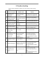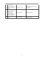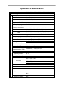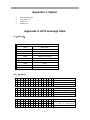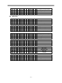
1
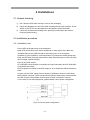
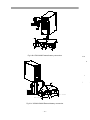
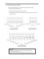
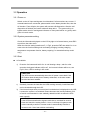
All rights reserved. The information in this document is subject to change without notice. Publish statement Thank you for purchasing this series UPS. This series UPS is an intelligent, three phase in single phase out, high frequency online UPS designed by our R&D team who is with years of designing experiences on UPS. With excellent electrical performance, perfect intelligent monitoring and network functions, smart appearance, complying with EMC and safety standards, This UPS has become standard product meets the world’s advanced level. Read this manual carefully before installation This manual is for Equipment operator Technical support - 1 - Safety Instruction 1. Prohibition 1.1There is a high risk of electric shock from the UPS inside, so please don’t not open or remove the casing or front panel unless it is operated by authorized technicians, otherwise warranty becomes void as well. 1.2 Please contact and discuss with distributors before connecting the UPS to following equipments Medical equipments which have direct relationship with patients’ life Equipments like elevators which may do harm to human beings Similar equipments as mentioned above 1.3 Don’t dispose of the battery with fire so as to avoid explosion 2. Safety notice 1) Output of standard UPS reconfigured with internal batteries may be energized even if the UPS input is not connected to the utility 2) Do disconnect the UPS input and make sure the UPS is completely off before moving the UPS or reconfigured the connection; otherwise, there will be potential electric shock. 3) For the sake of human being safety, please well earth the UPS before starting it. 4) Working environment and storage way will affect the lifetime and reliability of the UPS. Avoid letting the UPS work under following environment for long time Area where the humidity and temperature is belong the specified range(temperature 0 to 40℃, relative humidity 5%-95%). 5) Direct sunlight and location nearby heat Area which can be crashed easily Area with erosive gas, flammable gas, excessive dust, etc. Keep the ventilations in good conditions otherwise the temperature of components inside UPS will be high and the component and UPS life will be affected. 6) It is forbidden to pour liquid or put any objects into the UPS. 7) Don’t use liquid extinguisher if there is a fire, a dry powder extinguisher is recommended. - 2 - 8) Battery life cycle will be shorter as environment temperature rise. Replacing battery periodically can help to keep UPS in normal status and assure backup time required. Battery replacement should be done by authorized technician. 9) Keep the UPS in a dry area or environment if it will not be free of operation for long time. Storage temperature of UPS with internal battery is -20℃ to 55℃.extended backup model without internal battery is -40℃ to 70℃. 10) Taking out the UPS or batteries from storage, it is recommended to connect them with the utility for at least 12 hours per 3 months to avoid battery damage 11) Don’t open the battery, electrolyte inside will do harm to eyes and skin. Please use plenty of clean water to wash if touching and go to see a doctor right away. - 3 - Contents 1.Product Introduction - - - - - - - - - - - - - - - - - - - - - - - - - - - - - - - - - - - - 6 1.1 Application- - - - - - - - - - - - - - - - - - - - - - - - - - - - - - - - - - - - - - - - - - - 6 1.2 Product range - - - - - - - - - - - - - - - - - - - - - - - - - - - - - - - - - - - - - - - 6 1.3 System principle diagram - - - - - - - - - - - - - - - - - - - - - - - - - - - - - - - 6 1.4 Features- - - - - - - - - - - - - - - - - - - - - - - - - - - - - - - - - - - - - - - - - - -7 1.5 Product overview- - - - - - - - - - - - - - - - - - - - - - - - - - - - - - - - - - 7 1.5.1 Product view- - - - - - - - - - - - - - - - - - - - - - - - - 7 1.5.2 LCD Operation instruction- - - - - - - - - - - - - - - - - - - - - - - 8 1.5.3 Display instruction - - - - - - - - - - - - - - - - - - - - - - - - - - - - - - - 11 1.5.4 Rear panel instruction - - - - - - - - - - - - - - - - - - - - - - - - - - - - - - - - - - - - 16 2.Installation- - - - - - - - - - - - - - - - - - - - - - - - - - - - - - - - - - - - - - - 18 2.1 Unpack checking- - - - - - - - - - - - - - - - - - - - - - - - - - - - - - - - - - - - - 18 2.2 Installation procedure - - - - - - - - - - - - - - - - - - - - - - - - - - - - - - - - - - 18 2.2.1 Installation note- - - - - - - - - - - - - - - - - - - - - - - - - - - - - - -18 2.2.2 Installation - - - - - - - - - - - - - - - - - - - - - - - - - - - - - - - - - - - - - 19 2.3 Connection of parallel system - - - - - - - - - - - - - - - - - - - - - - - - - - - - 23 3.Operation- - - - - - - - - - - - - - - - - - - - - - - - - - - - - - - - - - - - - - - -24 3.1 Working Modes- - - - - - - - - - - - - - - - - - - - - - - - - - - - - - - -24 3.1.1 AC mode - - - - - - - - - - - - - - - - - - - - - - - - - - - - - - - 24 3.1.2 Bypass mode- - - - - - - - - - - - - - - - - - - - - - - - - - - - - - - - - - 24 3.1.3 Battery mode- - - - - - - - - - - - - - - - - - - - - - - - - - - - - - - - - - 24 3.1.4 ECO mode - - - - - - - - - - - - - - - - - - - - - - - - - - - - - - - - - - - - - 25 3.2 Operation- - - - - - - - - - - - - - - - - - - - - - - - - - - - - - - - - - - - - - - - - - - - - 26 3.2.1 Power on - - - - - - - - - - - - - - - - - - - - - - - - - - - - - - - - - - - - - 26 3.2.2 System parameter setting- - - - - - - - - - - - - - - - - - - - - 26 3.2.3 Start - - - - - - - - - - - - - - - - - - - - - - - - - - - - - - - - 26 3.2.4 Manual battery testing- - - - - - - - - - - - - - - - - - - - - - 27 - 4 - 3.2.5 Invert power off- - - - - - - - - - - - - - - - - - - - - - - - - - - - - - - - - - 27 3.2.6 Power off - - - - - - - - - - - - - - - - - - - - - - - - - - - - - - - - - - - - - 27 3.3 Working Mode and transferring - - - - - - - - - - - - - - - - - - - - - - - - - - - - - - - - 28 3.3.1 Transfer to bypass if overload - - - - - - - - - - - - - - - - - - - - - - - - - - - 28 3.3.2 Normal mode to battery mode - - - - - - - - - - - - - - - - - - - - - - - - - - -28 3.3.3 Goes to Bypass mode due to over temperature - - - - - - - - - - - - - - - 28 3.3.4 Output short circuit - - - - - - - - - - - - - - - - - - - - - - - - - - - - - - - - - - - - -28 3.4 UPS monitoring- - - - - - - - - - - - - - - - - - - - - - - - - - - - - - - - - - - - - - 29 3.5 LCD operation menu- - - - - - - - - - - - - - - - - - - - - - - - - - - - - - - - - -29 3.5.1 Main menu switching - - - - - - - - - - - - - - - - - - - - - - - - - - - - - - - 29 3.5.2 Submenu switching - - - - - - - - - - - - - - - - - - - - - - - - - - - - - 29 3.5.3 Priority of info displayed on LCD- - - - - - - - - - - - - - - - - - - - - - - - - 29 4. Maintenance- - - - - - - - - - - - - - - - - - - - - - - - - - - - - - - - - - - - 30 4.1 Fan maintenance - - - - - - - - - - - - - - - - - - - - - - - - - - - 30 4.2 Battery maintenance- - - - - - - - - - - - - - - - - - - - - - - - 30 4.3 Visual checking- - - - - - - - - - - - - - - - - - - - - - - - - - 30 4.4 UPS status checking- - - - - - - - - - - - - - - - - - - - - - - - 31 4.5 Func tion c hec k ing- - - - - - - - - - - - - - - - - - - - - - - 31 5. Trouble shooting- - - - - - - - - - - - - - - - - - - - - - - - - - - - - - - - - - - - 32 A1 RS232 communication port definition - - - - - - - - - - - - - - - - - - - - - - - - - - - - 34 A2 Specification- - - - - - - - - - - - - - - - - - - - - - - - - - - - - - - - - - - - 35 A3 Option - - - - - - - - - - - - - - - - - - - - - - - - - - - - - - - - - - - - - - 37 A4 UPS message table - - - - - - - - - - - - - - - - - - - - - - - - - - - - - - - - - - - - - - 37 - 5 - 1. Production 1.1 Application This series UPS, providing reliable AC power to various equipment, can be used for computer center, network management center, auto control system, telecom system, etc. 1.2 Product range Capacity Model Remarks 10kVA Standard model with internal battery Extended model 15kVA 20kVA Standard model Extended model External battery with internal battery External battery 1.3 System principle diagram The system can not only work as single unit, but also as parallel units to enhance the reliability. Fig.1-1 Single unit - 6 - 1.4 Features This series 10kVA/15kVA /20kVA UPS is newly introduced. sine wave UPS. It is an intelligent online High frequency, double conversion, high input power factor, wide input voltage range, the output will not be disturbed by power network, suitable for area with poor power supply condition DSP technology for all-digital control, high reliability, self-diagnostics and protections are featured in. Intelligent battery management which extends battery life LCD panel and LED indicators clearly indicate the system status and parameters such as input/output voltage, frequency, load, temperature inside UPS, etc. Perfect network power management can be achieved by using UPS monitoring software Maintenance bypass switch is provided so the power supply to load will not be interrupted while repairing Friendly maintenance module design, easy to maintenance. 1.5 Product overview 1.5.1 Product view F1-2 Complete unit view - 7 - 1.5.2 LCD Operation instruction LCD control panel consists of LCD display board, LED and buttons, see Fig1-3, which displays and controls these information including operating information, alarm information, function setting information. LCD control panel 1) 2) 3) Five green LED and one red LED LCD control panel which can display two lines of Chinese or four line of English Button : On, Off, ESC, Enter, and Left ,Right. ON OFF ESC FAULT BYPASS RECT INV OUTPUT ENT Fig.1-3 LCD control panel introduction 1. 2. 3. 4. 5. 6. 7. LCD Display Board ESC Off button On button right or down Enter left or up 8. 9. 10. 11. 12. 13. - 8 - Output Indicator Inverter Indicator Battery Indicator Mains (AC) Indicator Bypass Indicator Fault Indicator LED indicator definition 1) 2) 3) 4) 5) 6) Fault Indicator(red):On indicates when a fault occurred; Off means no fault Indicator(Green):On means AC is normal, Off means AC is not present, blinking means voltage is beyond normal range Inverter Indicator(Green):On : when load is powered by inverter, Off : when it is not working, blinking: when overload Bypass Indicator(Green):On : when UPS is in bypass mode, Off: not in bypass mode; blinking: when the input is beyond normal range Battery Indicator(Green):On: when UPS is in battery mode, Off : Not in battery mode; Blinking: when battery voltage is low or battery is not connected Output Indicator(Green):On: when there is output, Off: no output. LCD display content 1) Running parameters Input voltage/frequency, output voltage/frequency/current, temperature inside UPS, battery charging/fully charged, battery voltage. 2) Alarm information ( priority from high to low ) Shutting down, auxiliary power fault, output short circuit, inverter fault, rectifier fault, over temperature, overload, charger fault, battery fault, ready to shut down, output fault. 3) Parameter setting Menu setting, floating /boosting charging setting, battery capacity setting, ID of parallel UPS, output voltage/frequency level/calibration. Boosting charging voltage 2.30 to 2.35V per cell floating charging voltage 2.20 to 2.29V per cell Battery capacity setting includes the above each battery unit, battery quantity (8 to 10 )*2, parallel group number, low battery voltage alarm value (EOD ). Parallel setting UPS ID setting LBS setting ( Enable/Disable, Master/Slave) - 9 - Button definition Button Definition ON Switch on the inverter by pressing and holding it for 1s when the UPS is off OFF Switch off the inverter output by pressing and holding it for 1s when the UPS is on, load will be powered by bypass output if the bypass is normal ENT Confirm the operation ESC cancel to up menu ◀ Turn to another menu or parameter ▶ Turn to another menu or parameter UPS Messages reference table Explain Content Initialization CurState: Init No export No-Out At bypass Bypass Rectifier working Mains Battery invert Battery Battery testing Testing Starting Startin ECO mode CurState : ECO EPO mode CurState: EPO UPS maintaining CurState: M-Byp UPS fault CurState:Fault Battery float charging Battery Charging Battery Boost charging Battery Boost Inverter working or no Inverter ON/ Inverter OFF Master of UPS Inver Master Maintenance switch close or open - 10 - SWMB ON/ SWMB OFF 1.5.3 Display instruction 1) The main interface below comes out when the power is connected or the system is in cold start. See Fig1 YDC9310 10KVA Fig.1:Main interface 2) Press any key, it will change to the basic status interface , see Fig2 below MODE:On-Line Volt:AN BN CN Vin: 220 219 221 Vout:220 Fig.2:Basic status interface 3) Press the ◀ or ▶ button, it will change to main menu, see Fig3, FIGURE STATUS SETTING COMMAND Fig.3: Main menu 4) An arrow icon will come out on the LCD when pressing the ENT, then, the data info, status info, setting info, command control can be selected by pressing the right or left arrow button, and checking the details by pressing 5) Select and confirm the data info to be viewed in detail. It contains the details of the AC input /output , inverter, battery , BUS, parallel , temperature. See Fig 4~Fig 12 below. Figure Mains A:225.9 B:224.8 C:225.5 Figure Output 220.0V 0.0A 50.0HZ Load: 0% Fig.4:MAIN INPUT INFO Fig.5:OUTPUT INFO - 11 - Figure Output 0KW PAK: 0 0KVA Fig.6:OUTPUT INFO Figure INVERT 220.0V 50.0HZ Fig.7:INVERT INFO Figure BUS VOLT -390V +390V Fig.10:BUS INFO 6) Figure PBATT Discharge 0V 0.0A Fig.8:BATTERY INFO Figure PARALLEL ID:01 Figure NBATT 0V 0.0A Fig.9 BATTERY INFO Figure Temperature 00℃ Fig.12:TEMPERATURE INFO Select and confirm the status info to be viewed in detail, including status information, alarm information, code, power rating, version. See Fig 13~Fig 19 STATUS State Alarm & Fault Rated POWER Fig.13:main menu STATUS Status Main supply MB Switch close Fig.15:status info STATUS Code/Status 01 0x00 02 0x000000 Fig18:code info Fig.11:PARALLEL INFO STATUS Rated POWER Code Version Fig.14:main menu STATUS Alarm Fig.16:Alarm info STATUS Version LCD Ver. D000B001 DSP Ver. D000B001 Fig19:version info - 12 - STATUS Rate power MechInfo: 0101 Rated: 10KVA Fig.17:type info 7) Select and confirm setting menu , setting information will be displayed on the screen, which includes client setting, system setting, parallel setting, battery setting, correct setting. Setting User set System set Parallel set Fig.20:setting menu Setting Battery Set Fig.21:setting menu Select and confirm client setting ,then see Fig. 22. Setting User Set BL. ON BackLight 2 Fig.22:User setting information Select and confirm system setting menu ,then see Fig23~Fig28 Setting System set V-level 220V F-level 50HZ Fig.23:system setting Setting System Set V-Fine 0% SW Times 9 Fig.26:System setting Setting System Set Auto Enable F-Range 5% Fig.24:system setting Setting System Set Mode On-Line POWER Enable Fig.27:System setting - 13 - Setting System Set V-Upper 15% V-Lower -45% Fig.25:system setting Setting System Set POWER Enable Buzzer Disable Fig.28:System setting Select and confirm parallel menu,then see Fig.29~Fig.30 Setting Parallel ID P-Amount Set 1 1 Fig.29:Parallel setting Setting Parallel Set P-Redund 0 LBS NO LBS Fig.30:Parallel setting Setting battery see Fig. 31~Fig. 34 Setting Battery Set EOD 1.60 Batt Num 10 Fig.31:battery setting Setting Battery Set Batt-G 1 Batt-C 7 Fig.32:battery setting Setting Battery Boost Float Set 2.30 2.20 Fig.33:battery setting Setting Battery Set Boost Enable Fig.34 Battery setting Control operation see Fig.35~Fig.40 Command Battery Test Turn On Delay Batt.Cap.Test Fig.35:control menu Command For: 1sec Ent: sure Esc: cancel Fig.37 Battery self-test Command Battery Test Turn Off Delay Batt.Cap.Test Fig.36:control menu Command STOP Testing Ent: sure Esc: cancel Fig.38 stop battery testing Command Batt. Cap.Test Ent: sure Esc: cancel Fig.40 Battery capacity self-test - 14 - Command After: 1sec Ent: sure Esc: cancel Fig.39 Turn on/off delay 8) Warning message see Fig.41~Fig.46 Warning! Set no Echo:31 Warning! Set Error:31 Warning! Interrupt switch prompt Sure:Ent No:ESC Fig.41 no echo for setting Fig.42 error for setting Fig.43 switch delay Warning! Off will cause sys.Overload Sure:Ent No:ESC Warning! Off will cause output fail Sure:Ent No:ESC Warning! Switch Limited Sure:Ent Fig.45 no output due to shutdown Fig.46 switch times Fig.44 overload due to shutdown - 15 - 1.5.4 Rear panel instruction Fig.1-4 YDC9310H/S Rear Instruction 1) 2) 3) 4) 5) 6) 7) 8) 9) 10) 11) AC input Maintenance bypass switch (covered) Handle Output Input Dry contact RS232 RS485 Intelligent slot Parallel slot External battery connector - 16 - 1) 2) 3) 4) 5) 6) 7) 8) 9) 10) Fig.1-5 YDC9315/YDC9320 Rear Instruction Input Output AC input Maintenance bypass switch Dry contact RS232 RS485 Intelligent slot Parallel slot External battery connector - 17 - 2 Installations 2.1 Unpack checking 1) 2) 3) Don’t lean the UPS when moving it out from the packaging. Check the appearance to see if the UPS is damaged during the transport, do not switch on the UPS if any damaged found and please contact the dealer. Check the accessories according to the packing list and contact the dealer if found any parts missing. 2.2 Installation procedure 2.2.1 Installation note Put the UPS at flat place next to the equipment. Keep UPS at least 20cm from wall or equipment or other object. Don’t block the ventilation holes of the UPS front panel and bottom part, so as to keep the ventilation in good conditions, avoid temperature of components inside getting high. Keep the UPS away from high temperature, water, flammable gas, erosive gas, dust, direct sunlight, explosive things Don't lay the UPS outdoor 3P 125A/400V circuit breaker is required at the input and battery and 2P 125A/400V is required at the output. PDU is required to connect to the UPS output so as to weaken the affection between loads In order to fix the UPS, please lock its wheels by shifting the sheet on each wheel. RCD load like computer ,linear load and small inductive load can be connected with the UPS. Please contact dealer if other types of loads is required to connect. For the sake of user and equipments, please betake correct power configuration. Fig.2-1a Correct power configuration - 18 - Fig.2-1b Wrong power configuration 2.2.2 Installation External battery connection (for extended model only ) 1) 2) 3) 4) Make sure battery quantity complies with the specs. Measure the voltage of battery bank after finishing connection and the battery voltage should be around 240VDC. Don’t mix batteries with different capacity, manufacturers and don’t mix brand new and old batteries, either. The breaker onto battery cabinet should be off. Take out the connection box and remove the cover of terminals, use multi-meter to make sure there is no DC voltage at the battery terminals of UPS. Connect battery pole with positive pole, negative pole and common pole to battery connecter(BAT+,BATN,BAT-), don’t reverse battery connection. CAUTION It is recommended to connect or replace battery after switching off the system; don’t reverse battery connection when doing battery hot-swapping. A B C N N L Fig.2-2a YDC9310S External battery connection - 19 - A B C N N L BAT+ BATN BAT- BAT+(8/9/10) BAT-(8/9/10) Fig.2-2b YDC9310H External battery connection BAT- BATN BAT+ A B C N N L BAT-(8/9/10) BAT+(8/9/10) Fig.2-2c YDC9315/9320 External battery connection - 20 - UPS input and output connection Minimum 5AWG copper wires are required for the 10K-20KVA, including input/output cables, battery cables. 1) Switch off all breakers before connecting cables 2) Remove the cover of the terminals, see Fig 2-3, then follow them to connect the cables correctly. Fig.2-3a YDC9310S I/O terminals connection Fig.2-3b YDC9310H I/O terminals connection Fig.2-3c YDC9315/9320 I/O terminals connection CAUTION Terminators are required so as to ensure the connections are firm Don’t reverse the input L and N Don’t connect the UPS input to a wall outlet or the outlet will get burnt. - 21 - 3) Connect the UPS output L, N, E to L, N, E of load via a PDU. Tighten the screws and shelter the terminals WARNING! Please connect the output Earth well before other operation Connection of the UPS communication cables 1) 2) RS-232 cable provided in accessories can be used to connect the UPS with PC Follow step below is to install SNMP (if purchased ): A. Remove the cover of SNMP slot at UPS rear panel and keep it for further use. B. Insert the SNMP card and tighten the screws C. Connect the UPS with internet by network cable. D. Refer to the SNMP manual provided to do SNMP setting - 22 - 2.3 Connection of parallel system UPS1 Parallel cable Parallel cable Parallel cable UPS2 UPS3 UPS4 Fig.2-4 parallel system Make sure all the breakers are off and no output at the UPS output. CAUTION Connect the A/B/C/N/L and E well Configured individual battery bank for each extend backup UPS in parallel system. Don’t use common battery bank. Parallel cables: When the UPSes are connecting in parallel, the copper wires required to connect with each UPS is minimum 5AWG, but the main wire for linking all the UPS in parallel should be N* 5AWG(N refers to the number of the UPS in parallel.) Make sure the cables are as shorter as possible to reduce any possible noise interference to data transfer. - 23 - 3. Operation 3.1 Working modes The UPS has AC mode, bypass mode, battery mode and ECO mode 3.1.1 AC mode If the AC input and load capacity are in normal ranges, load will be powered by inverter output, battery will be charged at the same time. AC and inverter indicators on LCD control panel will be on (green). CAUTION Please note below if the UPS input power is provided by a generator 1) Don't switch on the loads before starting UPS. After the UPS has been started and worked steadily, switch on the loads one by one. Suggest that the total capacity of the loads should be lower than 30% of capacity of the generator 2) It is suggested that the rating of generator should be 1.5-2 times of the capacity of the UPS. 3) When several UPSes are connected in parallel, all the UPS may share with one battery bank only, which means the 10-20Kva are common battery type UPS. 3.1.2 Bypass mode When the AC power is connected and the UPS has not been switched on, or the UPS is overloaded after switching on the UPS, it will go to bypass mode. The Loads will be powered by AC, battery will be charged, the bypass indicator on the LCD control panel will be on (green). But, if the bypass is beyond normal range or absent, the UPS will not go to bypass mode and no power will be supplied to the loads. 3.1.3 Battery mode In AC mode, if the AC is absence or beyond normal range, the rectifier and charger will stop working, the loads will be powered by battery bank of which energy goes through inverter circuit. The Inverter’s and battery’s indicators on LCD control panel will be on (green) and the alarm will beep every 3 seconds. In battery mode, if the battery voltage becomes low and reaches the setting value, the system will give low battery voltage alarm, beep once every second and the LCD will give low battery alarm, too. CAUTION Charge batteries for at least 8 hours when the UPS is used at the first time although the UPS had been fully charged by manufacturer - 24 before shipping. 3.1.4 ECO mode In AC mode, the UPS can be set to work in ECO mode if the load has no strict requirement on the power purity and the UPS can stay in bypass mode normally. If the AC is beyond normal range, the UPS will transfer back to inverter mode. The Efficiency for the UPS in ECO mode is much higher. - 25 - 3.2 Operation 3.2.1 Power on Switch on the AC input and bypass circuit breakers if all connections are correct. If external batteries are connected, please switch on the battery breaker first, then the AC breaker. Fans will spin, the system will execute self-diagnostics. After the self diagnostics is finished, the buzzer inside will beep twice. The system will go to bypass mode, then AC and bypass indicators on front panel will be on (green) and it goes to inverter mode. 3.2.2 System parameter setting Check the information displayed on the LCD by right or left arrow button, press ESC to quit from the main menu. When the function setting interface as P.11 Fig3, press the ENT then hold it for 1s to enter to do the function setting such as floating charging, boosting charging, temperature compensate function, battery capacity ( for extended backup model only ) 3.2.3 Start AC available 1) Press the On button and hold it for 1s until hearing a beep , wait for a few seconds, the bypass indicator will be off , the inverter indicator will be on, see Fig3-6, then, UPS is working in AC mode CAUTION The UPS can start automatically when the AC power comes back if the UPS shuts down already due to battery exhausted, or the auto restart function has been enabled. 2) 3) Gradually increase the load after the UPS working normally. Load information can be checked through the LCD. If the buzzer beeps twice per second and overload alarm is displayed on the LCD, it means the system is overloaded. Please decrease the load immediately.70% of load is recommended in case suddenly added load will not affect the UPS work normally CAUTION If the UPS has transferred to bypass mode due to overload for several times and reach the setting times in 1 hour, it will keep in bypass mode unless manually transfer to inverter mode or automatically transfer to inverter mode 1 hour later without overloading - 26 - Battery mode UPS can start in battery mode even if the AC is absent. Press the On button and hold for 1 second until hearing one beep, battery and inverter indicators will be on after finishing self-diagnostics. The UPS will beep once every 3 seconds which means it is working in battery mode 2) Add load as in AC mode above. 1) CAUTION Please decrease load immediately if the system is overloaded; otherwise, it will shut down in some time. 3.2.4 Manual battery testing When the inverter is working, the input AC is normal , and the UPS is not overloaded, and the battery voltage is not lower than 12V per block, the battery testing can be carried out by pressing the button on the LCD control panel. When the battery is being tested, the buzzer will beep and the battery indicator will blink. When the testing is complete, the buzzer stops beeping, the battery indicator stops blinking, and the UPS will recover to status before testing. If there are some problems with the batteries, the LCD will show details CAUTION The battery status info will be re-fresh every time after the testing. The Battery fault info checked out by testing due to battery weak can be eliminated automatically after fully charging. 3.2.5 Inverter shutdown 1) 2) If the AC is normal, press the off button and hold for 1 second until hearing one beep, the inverter indicator will be off , the bypass indicator will be on and the UPS will work in Bypass mode If the AC is absent, press the off button and hold for 1 second until hearing one beep, the UPS will shut down the output ,the LCD will display shutting down. 3.2.6 Power off After switching off the inverter, switch off the AC and the battery circuit breaker, the LCD control panel will be off and the fan will stop. If there is a battery bank connected, it will take 30 seconds to shut down the system completely The power of the load(equipment) will be cut off when the UPS is powered off - 27 - 3.3 Working Mode and transferring Usually, the UPS should be set to work in AC mode, so it will transfer to battery mode automatically without interruption when AC is failed. When the UPS is overloaded, it will transfer to bypass mode without interruption. When the inverter is defective or over-temperature, the UPS will transfer to bypass mode if the bypass is normal. 3.3.1 Transfer to bypass if overload When the load of UPS is beyond normal range and lasts for setting time, it will transfer to bypass mode and beeps twice every second. Then, the load is powered by AC directly, at that time, please decrease the load immediately until the alarm is eliminated. The UPS will start the inverter after 5 minutes. In order to protect the load and the UPS, it has set the limitation of times of transfer to bypass mode due to overload in 1 hour. If it exceeds the limitation, UPS will keep in bypass mode. 3.3.2 Normal mode to battery mode The UPS will go to battery mode if AC is failed. The UPS will shut down automatically if battery has been exhausted. When AC recovers, the UPS will start inverter automatically. If the UPS was shut down manually in battery mode, when AC recovers, it will remain in Bypass mode, which means you can not start the inverter automatically. 3.3.3 Goes to bypass mode due to over temperature The temperature inside of the UPS may be high if ambient temperature is high or the ventilation is poor, then the UPS will go to Bypass mode, the fault indicator will be on (red), the LCD will display the inner temperature is high and long beeps will come. If so, please cut off the input power of the UPS, move objects affecting the ventilation away from the UPS if any or increase the distance between UPS and the wall. Wait until the UPS temperature becomes normal then restart it. 3.3.4 Output short circuit When the UPS output is in short circuit, the UPS will cut off the output, the fault indictor will be on ( red ), and the LCD will display that output is in short circuit and long beeps come. If so, please disconnect the load in short-circuit, cut off the UPS input power and wait for 10mins, the UPS will shut down automatically or press the off button to shut down within 10s.Before restarting the UPS, please make sure that the short circuit problem has been solved - 28 - 3.4 UPS monitoring Please refer to the instruction of the UPS monitoring software provided. 3.5 LCD operation menu 3.5.1 Main menu switching Press the left/right arrow and the ENT button can switch among alarm info, running parameter and function settings. Press the ENT to enter alarm info, running parameter or function settings. To enter function setting, double pressing on the ENT is required. 3.5.2 Submenu switching 1) 2) 3) 4) 3.5.3 Press the arrow button can view details after entering the running function interface, press the ESC to return to main menu. Press the arrow button can view details after entering the function settings interface, press the ESC to return to main menu Parameter which has been selected and changed will be highlighted. Press arrow button to change the value and press the ENT to confirm the value. Once confirmed, it will not be highlighted. Press the arrow button can view detailed alarm info after entering the alarm info interface, press the ESC to return to main menu Priority of info displayed on LCD 1) 2) If there is alarm but no valid operation on buttons, the alarm info with top priority will be shown on the LCD automatically When there isn’t any alarm and the LCD is displaying the submenu of running parameters, such as output current, these parameters will be always displayed on the LCD if no operation on buttons. If the LCD is not displaying the submenu of running parameters, it will return to main menu in 30s if there is no operation on buttons - 29 - 4 Maintenance Please follow 2.2.1 to install the UPS 4.1 Fan maintenance Continual working time of the fan is 20000 to 40000 hours. It will be shorten as temperature raises. Please check the fan periodically, make sure there is wind blown out front it. 4.2 Battery maintenance There are sealed lead acid maintenance free batteries inside the UPS if it is standard model. Battery life depends on environment temperature and discharge/charge cycles, it will be shorter if temperature raises or deep discharged. Periodical maintenance is required so as to keep battery in good conditions. 1) The most proper working temperature is 15 to 25 Celsius degree. 2) Avoid small discharging current. Don’t let UPS work in battery mode continuously for 24 hours. 3) Charge battery for at least 12 hours every 3 months if it is free of operation. If the environment temperature is high, charge it once every 2 months. 4) For extended backup models, check and clean the battery connectors periodically.。 If backup time has become much less than before, or there is battery fault displayed on the LCD, please contact distributors to confirm whether the batteries need to be replaced or not. CAUTION 1) Don't short circuit battery, or it may cause a fire. 1) Don’t open battery, released electrolyte is harmful to skin and eyes 4.3 Visual checking Keep the ventilation of the UPS in good condition - 30 - 4.4 UPS status checking 1) 2) 3) To check to see if there is any fault , the fault indictor is on or any alarm there or not. Please find the cause if the UPS is working in bypass mode. If the UPS is working in battery mode, make sure it is normal; on the contrary, please find out the cause 4.5 Function checking Do function checking once every 6 months. 1) Press the off button to see if the buzzer and indicators and the LCD are normal or not. Please refer to 3.1 2) Press the On button, check the indicators, the LCD and the UPS inverter, and make sure they are normal 3) When the UPS is working in normal, do battery testing to test battery. - 31 - 5 Trouble shooting Please contact the distributor if problems can not be solved by trouble shooting below No Problem description Probable causes Solution 1 No display on the LCD, no selfdiagnostics A Input power absent B Low input Use Multi-meter to measure the input to see if it is normal or not. 2 AC normal but AC indicator off, the UPS is in battery mode A Input circuit breaker off. B Input power connection problem A Switch on the input breaker B Check the connection and re-do 3 No alarm but no output Output connection problem Check the connection and re-do 4 UPS doesn’t start after pressing On button pressing ON button time is insufficient B Overload A Press and hold On button for 1s B Disconnect all loads and restart 5 AC indicator blinking Input AC is beyond normal range Pay attention to the backup time if the UPS is in battery mode 6 Buzzer beeps twice every second, the LCD shows “output overload” UPS overload Disconnect some loads 7 ”Fault indicator On and the LCD shows “battery fault” A Battery circuit breaker off or poor connection B Reverse battery connection C Battery defective A Switch On the breaker, check the battery connections B Check the battery polarity C Contact distributor to replace battery 8 Fault indicator on, the LCD shows ”charger fault “ Charger defective Contact distributor A Battery not fully charged B Battery terminate A Charge battery for 8 hours when AC is normal, then test the backup time again B Contact distributor to replace battery Over temperature inside UPS A Check to see if there is wind blown out from the fans B Move objects away from the UPS C Wait till the UPS cools down and restart UPS 9 10 Abnormal backup time Long beeps, fault indicator on, LCD show… - 32 - 11 12 13 Long beep fault indicator on, the LCD shows “output short circuit ” Output short circuit Eliminate the short circuit and restart UPS Long beeps, fault indictor on, the LCD shows“ rectifier fault”/“inverter fault”/“auxiliary power fault”/“output fault” Fault inside UPS Contact distributor Abnormal sound or smell Fault inside UPS shut down UPS immediately and Contact distributor Please provide the UPS model, SN when calling distributor for maintenance. 、 - 33 - Appendix 1. RS232 communication port definition Definition of Male port: Pin 2 receive, pin 3 send, Pin 5 ground, others floating Connection between PC RS232 port and UPS RS232 port PC --------------------- UPS RDX 2<------------------- TX 2 TDX 3--------------------> RX 3 GND 5--------------------- GND 5 Available function of RS232 ■ Monitor UPS power status ■ Monitor UPS alarm info ■ Monitor UPS running parameters ■ Timing off/on setting RS-232 communication data format Baud rate ---------- 2400bps Byte length ---------- 8bit End bit ---------- 1bit Parity check ---------- Null - 34 - Appendix 2. Specification Capacity 10KVA/8KW 15KVA/12KW 20KVA/16KW Type 10KVA-H/S 15KVA-H 20KVA-H Input mode Three phase Power factor ≥0.99 rated voltage 220VAC/230VAC(can be set) rated frequency 50Hz/60Hz(can be set) input Voltage range 145~280V Frequency range 40~70Hz Bypass voltage range Bypass frequency range THDI Battery number Battery type battery Charge model Charge time Charge current(A) Output type Output precision Voltage distortion(THD) Rated voltage Frequency precision Rating Frequency Frequency track speed max:+5%, +10% or +15%, default +5% min:-20%, -30% or -45%, ±1%、±2%、±4%、±5%、±10% 5%(100% liner load,input THDV ≤1%) 7% (100% non liner load,input THDV ≤1%) 2*(8~10)(12V) VRLA Boost charge or float charge auto switch Boost charge up to 20Hr(Max) 1A(S) 6A(H) Three line of single-phase 1.0%; less than 2% at 100% liner load less than 3.5% at 100% non-liner load 220/230V ±0.1% 50Hz/60Hz 1Hz/s 105%~110%,1Hr output Overload 110%~125% 10min 125%~150% 1min ≥150% Overload for bypass Peak value factor default -45% 200ms 125% 3:1 Efficiency at normal ≥90% Efficiency at battery mode ≥81% Efficiency of inverter ≥92% - 35 - Dynamic respond 5.0% 20ms ≤500mV DC heft Switching Between Normal mode and battery mode Between inverter and bypass Noise 0ms 0ms。 unlock:<15ms (50Hz), <13.33ms (60Hz) <55dB(1m) Display LCD+LED Safety Meet IEC62040-1 GB4943。 Max input voltage 320Vac,1Hr Conduction :IEC 62040-2 Radiation :IEC 62040-2 EMI Harmonics :IEC 62040-2 EMS IEC 62040-2 MTBF 250,000Hr 1+1 400,000Hr MTTR 30min Isolation resistance > 2MΩ(500Vdc) Isolation intension 2820Vdc, <3.5mA,1min Surge Meeting IEC60664-1 1.2/50uS+8/20uS Protection 6kV/3kA. IP20 Strike Meeting YD/T 1095 Package Meeting YD/T 1095 Traffic Meeting YD/T 1095 Parallel circumfluence 1+1≤8%,N+1≤3% Parallel equal current 1+1≤8%,N+1≤10% Dimension & weight DIMENSION Capacity KVA 10KVA/8KW High mm 655 Wide mm 250 Deep mm 590 Net weight kg 10KVA:76Kg(S)/35kg(H) 15KVA: 45kgs(H) 20KVA: Colour 15KVA/12KW 46kgs(H) Black - 36 - 20KVA/16KW Appendix 3. Option 1. Extended battery box 2. Dry contact card 3. SNMP card 4. Parallel card Appendix 4. UPS message table 01(running) 0x01 Non output 0x02 on bypass 0x03 on online 0x04 on battery 0x05 Battery self-testing 0x06 Inverter starting 0x07 ECO mode 0x08 EPO 0x09 maintenance bypass 0x0A Fault 02:(status) 8 4 2 1 5 3 3 6 7 6 7 5 4 1 5 3 3 6 7 6 7 5 9 7 4 1 5 3 3 5 6 7 6 7 7 9 9 9 B B C D E F EPO C D E F Rectifier working E F Rectifier limit F Input C B A B A B 9 8 2 A A 7 8 2 9 D C D E F C D E F charging E F P-battery boost charging F N-battery boost charging C B A B A B B normal D Input 1:main /0:battery C D E F Battery self-testing C D E F 00:shutdown;01:soft start; E F 0:no output;11:output normal F Alarm for switch delay C D - 37 - 8 4 2 1 5 3 3 6 7 6 7 5 7 2 1 5 3 3 6 7 6 7 5 2 1 5 3 3 6 7 6 7 5 B A B 9 A 9 9 D E F Capacity no enough C D E F Overload to shutdown E F Overload to bypass F Parallel to bypass C B B D C D E F Switch times up to limit C D E F Master E F MB switch close F Input switch close C B A A 7 C B A 7 8 4 A 9 8 4 9 9 B B D C D E F C D E F E F 0(hold) F 0(hold) C B D 00:no out;01:bypass;10:invert 03:(Alarm A) 8 4 2 1 5 3 3 6 7 6 7 5 4 1 5 3 7 3 6 7 6 7 5 9 7 4 1 5 3 3 6 7 6 7 5 7 2 1 5 3 3 6 7 6 7 5 2 1 5 3 3 6 7 6 7 5 4 1 5 3 3 5 7 6 7 7 B 9 9 A B A B 9 D E F Rectifier fault C D E F Rectifier over temp E F Invert over temp F rectifier over current C D C D E F Assistant supply 1 fault C D E F Assistant supply 2 fault E F Input SCR fault F discharge SCR fault Charge SCR fault C D C D E F C D E F Fan fault E F Fan supply fault F BUS over voltage C B A B B D C D E F BUS lower voltage C D E F BUS voltage of P-N different E F Phases wrong F Soft start fault C B A 9 9 C B A 7 6 A 9 8 2 B A 7 8 4 9 B A 9 8 4 9 B B 9 8 2 A A 8 2 9 B B D C D E F N loss C D E F Battery on the contrary E F No battery F P-charge fault N-charge fault C B A B A B B D C D E F C D E F Battery voltage lower E F Battery voltage higher F pre-alert for battery low C D - 38 - 8 4 2 1 5 3 3 6 7 6 7 5 7 9 A B A B 9 C D E F Frequency of Input over limit C D E F Voltage of Input over limit E F 0(hold) F 0(hold) C B D 04:(Alarm B) 8 4 2 1 5 3 3 6 7 6 7 5 2 1 5 3 3 6 7 6 7 5 9 2 1 5 3 3 6 7 6 7 5 4 1 5 3 3 7 6 7 5 4 1 5 3 7 3 6 7 6 7 5 2 1 5 7 3 3 5 6 7 6 7 7 9 9 B B B B A B E F Inverter fault C D E F Bridge cross of inverter E F Invert SCR short circuit F Invert SCR open circuit C D C D E F bypass SCR short circuit C D E F bypass SCR open circuit E F CAN communication fault F Current no equality for parallel Bypass phase wrong C D C D E F C D E F E F Bypass over track F Bypass over protect IGBT over current C D A B A B B B B fault D E F C D E F Fuse fault E F Parallel cable fault F Parallel relay fault C D C D E F LBS unlock C D E F Initialization fault E F Can’t start F overload C B A Sync C B A 9 B A 9 9 D B 9 8 4 A 9 8 2 9 B C B A 7 6 A 9 8 2 9 B B A 7 8 4 A A 7 8 4 9 D C D E F Parallel overload C D E F DC heft over limit E F Bypass over current F Feedback protect C D - 39 -