1
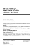
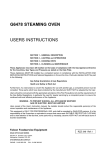
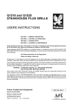
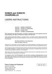
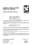
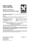
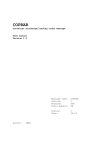
G2101 OTC
DOMINATOR RANGE
USERS INSTRUCTIONS
SECTION 1 - GENERAL DESCRIPTION
SECTION 2 - LIGHTING and OPERATIONS
SECTION 3 - USING THE APPLIANCE
SECTION 4 - CLEANING and MAINTENANCE
The appliance has been CE-marked on the basis of compliance with the Gas Appliance Directive, EMC and
Low Voltage Directive for the Countries, Gas Types, Pressures and Voltages as stated on the Data Plate.
The appliance MUST BE installed by a competent person in compliance with the INSTALLATION AND
SERVICING INSTRUCTIONS and National Regulations in force at the time. Particular attention MUST be paid
to the following:
Gas Safety (Installation & Use) Regulations
Health and Safety at Work Act
Furthermore, if a need arises to convert the appliance for use with another gas, a competent person must be
consulted. Those parts which have been protected by the manufacturer MUST NOT be adjusted by the User.
Users should be conversant with the appropriate provisions of the Fire Precautions Act and the requirements of
the Gas Safety Regulations. in particular the need for regular servicing by a competent person to ensure the
continued safe and efficient performance of the unit.
WARNING - TO PREVENT SHOCKS, THIS APPLIANCES MUST BE EARTHED
Upon receipt of the User's Instruction manual, the installer should instruct the responsible person(s) of the
correct operation and maintenance of the unit.
This equipment is ONLY FOR PROFESSIONAL USE, and shall be operated by QUALIFIED persons. It is the
responsibility of the Supervisor or equivalent to ensure that users wear SUITABLE PROTECTIVE CLOTHING
and to draw attention to the fact that, some parts will, by necessity, become VERY HOT and will cause burns if
touched accidentally.
Falcon Foodservice Equipment
HEAD OFFICE AND WORKS
PO Box 37, Foundry Loan, Larbert.
Stirlingshire. Scotland. FK5 4PL
AFE SERVICE CONTACT -
PHONE - 01438 751 111 FAX - 01438 369 900
RZZ 336 Ref.1
SECTION 1 - GENERAL DESCRIPTION
SECTION 2 - LIGHTING and OPERATIONS
The G2101 OTC is a dual fuel range with gas six Open Top
burner open top hob and electric fan convection oven.
Hob burners are fitted with individual flame failure
devices which shut off the gas supply to burners
should the flames be interrupted.
GAS CONTROLS
All gas taps are safety type and are fitted with flame
failure detection and HIGH and LOW settings.
Tap operation is illustrated in Figure 1.
Off position
Figure 1
1. Depress and turn control knob to full flame position.
2. Light burner using a taper or a match. Continue to
press knob in for 20 seconds before release.
3. The burner should remain lit. If burner goes out,
return to Step 1 and repeat ignition procedure.
4. Having lit burner, turn control knob to required
setting.
To Shut Off an Open Top Burner
Turn control knob to off position.
Oven
Low flame
setting (Simmer)
1. Ensure main supply is on. Red neon should light.
2. Turn control knob (see Figure 3) clockwise to
desired setting. Amber neon will light and remain lit
Maximum flame
until temperature is reached.
setting (High)
3. Do not leave doors open for longer than is
necessary to load or unload oven.
Open Top Gas Tap
Each tap is identified with it's corresponding burner.
(See Figure 2)
SECTION 3 - COOKING HINTS
Open Top
Open top burners rated at 4.5kW nett.
Figure 2
Boost burners rated at 5.3kW nett.
Positions are indicated in Figure 4.
Rear Burner
Front Burner
ELECTRIC CONTROLS
The electric control consists of a combined fan switch
and thermostat. Two neons, one RED, one AMBER
indicate Mains ON and Oven Heat ON respectively.
The control knob is identified by the symbols shown in
Figure 3 below.
Figure 3
Figure 4
The pan supports will safely accommodate pans from
125mm diameter. It is recommended however, that
pans larger than 300mm diameter be heated upon
the rear burners.
Oven
Temperature is automatically controlled by
thermostat. The cooking chart gives thermostat
settings and time required but for best performance,
follow these instructions.
Grid Shelves
Mains ON
INDICATOR
Thermostat control knob
and heat ON indicator
Space at least one runner apart (for example, use
positions 1, 3 & 5). Push shelves back into oven until
shelf stops hit front runners.
Tray Size
A cake tray up to 650mm x 530mm (Gastronorm 2/1)
may be used on each shelf. Single trays or dishes
should be placed centrally. Trays must not be allowed
to overhang the shelf in any direction since this will
adversely affect the heat circulation.
Pre-heat Time
Allow at least 15 minutes from switching oven on from
cold before loading with food. Insert dish quickly and
close doors firmly.
The oven is fan assisted. Cooking temperatures
should be lower than those of a conventional oven.
Cooking times may also differ.
Cooking times are dependant upon the following:
Pre-heat Temperature
Food Temperature
(e.g. frozen, chilled or ambient)
Shelf Load
Oven Load
Size and weight of food
Personal Preference
Five shelf positions are available.
Three shelves are supplied.
When using 3 shelves, we recommend that
Positions 1, 3 and 5 be used.
Chef's Tips
Always pre-heat the oven to the desired
temperature.
Use the appropriate trays.
Do not over load the oven.
Place the food upon the shelves centrally.
Avoid opening the oven doors during the cooking
process.
When removing food from the oven, ensure that
the doors are fully open.
Cooking Chart
The following information is based upon full loads
positioned on Shelves 1, 3 and 5. This information is
provided as guidance only and all figures are
approximate.
Temperature
(oC)
100
Time
(minutes)
180
Shortbread Biscuits
140
55
Croissants
170
25
Apple Turnovers
180
35
Fairy Cakes
200
15
Chickens
200
52
Vol-au-Vent Cases
210
18
Chicken Pies
210
33
Fruit Scones
220
13
Yorkshire Puddings
220
30
Food Product
Meringue Shells
SECTION 4 - CLEANING THE APPLIANCE
General
BEFORE ANY CLEANING OPERATION, ISOLATE
ELECTRICITY AT THE MAIN SWITCH.
THE APPLIANCE MUST NEVER BE CLEANED
WITH A JET OF WATER OR BE STEAMCLEANED.
Clean with soapy water as often as possible, rinse
and dry. Grease should be removed with fine steel
wool or proprietary cleaning pads. Nylon pan
scrubbers should be used with care, especially when
new as they may scratch the enamelled surfaces.
Before removing any parts, notice carefully how the
parts are arranged and replace them in the same
positions after cleaning.
Cleaning the Hob
4. Clean any spillage from the burner base, ensuring
all food and cleaning material debris is removed.
Dry burner base thoroughly, taking care not to
damage the flame sensor.
Flame Sensor
Figure 6
Important
Do not allow any spillage or cleaning material debris
enter large hole in burner base. This may cause
blockage of the gas injector.
The following instructions should be followed when :
a) A spillage has occurred on burner.
b) Burner fails to light or stay alight.
c) At the end of each day or cooking period.
Caution
Parts may be hot therefore protection to avoid burns
should be used.
1. Remove pan support.
2. Remove burner head and bezel by lifting upward.
Figure 7
5. Replace burner head and aluminium bezel upon
burner base and ensure that head location pips sit
within notches in burner bezel. When burner head
is properly located, it will not rotate.
Pips
Figure 4
3. Thoroughly clean with soap and water. Ensure that
all burner ports are clean and free from food or
cleaning material debris.
Important
Stubborn debris lodged in the ports (See Figure 5)
may be removed using a non-metallic implement
such as a cocktail stick. The slots in the base should
be freed of debris using a soft brush.
Dry the burner with a lint-free cloth and blow through
the ports to ensure there is no blockage.
Figure 5
Ports
Slots
Notch
Figure 8
6. Light burner to check that it operates correctly.
Note
This process should be followed prior to calling for a
Service Engineer. Failure due to lack of proper
cleaning is not covered by warranty.