1
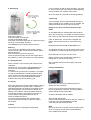
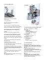
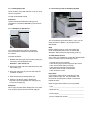
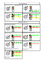
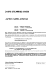
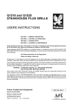
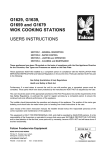
EFS 200, EFS 400,
EFS 402 FRYERS
Installation and Operating
Instructions
IMPORTANT
The installer must ensure that the installation of the appliance is in conformity with these instructions and
National Regulations in force at the time of installation. Particular attention MUST be paid to BS7671 IEE Wiring Regulations
Electricity At Work Regulations
Health And Safety At Work Act
Fire Precautions Act
This appliance has been CE-marked on the basis of compliance with the Low Voltage and EMC Directives for
the voltages stated on the Data Plate.
WARNING - THIS APPLIANCE MUST BE EARTHED
On completion of the installation these instructions should be left with the Engineer-in-Charge for reference
during servicing. Further to this, The Users Instructions should be handed over to the User, having had a
demonstration of the operation and cleaning of the appliance.
IT IS MOST IMPORTANT THAT THESE INSTRUCTIONS BE CONSULTED BEFORE INSTALLING AND
COMMISSIONING THIS APPLIANCE. FAILURE TO COMPLY WITH THE SPECIFIED PROCEDURES MAY
RESULT IN DAMAGE OR THE NEED FOR A SERVICE CALL.
PREVENTATIVE MAINTENANCE CONTRACT
In order to obtain maximum performance from this unit we would recommend that a Maintenance Contract be
arranged with FALCON SERVICE LINE. Visits may then be made at agreed intervals to carry out adjustments
and repairs. A quotation will be given upon request to the FALCON SERVICE LINE contact numbers below.
Falcon Catering Equipment
Head Office and Works
PO Box 37, Foundry Loan, Larbert
Stirlingshire, Scotland FK5 4PL
Service Line Contact
PHONE
- 01438 751111
FAX
- 01438 369900
1. Models and variants
Models
EFS200 - Single Pan (200mm wide)
EFS400 - Single Pan (400mm wide)
EFS402 - Double Pan (400mm wide)
3. Installing The Appliance
3.1 Free standing fryers
When installing the unit please observe the
following instructions (refer to diagramm below):
2. Technical Specifications
Model
Oil Capacity
(minimum)
Oil Capacity
(maximum)
Weight
EFS 200
EFS 400
EFS 402
7 litres
15 litres
2 x 7 litres
9 litres
18 litres
2 x 9 litres
34 kg
49 kg
52 kg
Cable Length - 2 metres (without plug)
Power Ratings
b) Minimum distances to be observed between the
fryer and the wall or other units; at the rear: 30 mm.
c) The fryer should not rest on an inflammable
surface. Observe the local security and building
regulations.
EFS 200 - 7.5 kW
EFS 400 - 15 kW
EFS 402 - 2 x 7.5 kW (15 kW)
Dimensions
Height ex factory: 900 mm
By adjustment of the feet: 850 mm
Spec. execution of feet: 800 mm
(To place the fryer under the working suface)
400
d) The fryer position should be fixed. The castors
are only intended to facilitate servicing or cleaning
of the unit. When installing a fryer equipped with
four castors, the two front castor brakes must be
locked.
Warning
The EFS 200 model cannot be left without any form
of permanent fixture and should be secured by
means of the two plates supplied.
400
750
Flat plate for
Variants 1 and 2
Perforation for
folding to 90 0
Angular plate for
variants 3 and 4
EFS 200
EFS 400
EFS 402
850
900 (Standard height)
100 - 150
850 - 900
57
200
a) Ensure that the fryer is level by means of the two
feet with adjustable screws (27 mm fork wrench).
To change the height from 900 mm to 850 mm or
vice versa:
Adjustment of height:
- Lift of lay down fryer
- Unscrew screws
- Adjust to desired height
- Put back screws and tighten
Various Fixing Methods:
1 - From one fryer to another (view from the back)
2 - To a kitchen cupboard (view from the back)
3 - To the wall (view from top)
4 - To the floor
b) Special power supplies
3AC 400V, 50Hz, 3L+PE
3
1
2
L1
L2 L3
4
5
PE
2
1
3AC 230V, 3L+PE
3
1
2
L1
L2 L3
4
5
cupboard
PE
AC 230V, L+N+PE
3
3
1
2
L1
L2 L3
4
4
N
5
PE
Fuse Sizes
bend to ''L''
Model
EFS 200
EFS 400
EFS 402
Rating
Supply
Fuse
Supply
Fuse
7.5 kW
3N˜400
16A
3N˜230
20A
15 kW
3N˜400
25A
3N˜230
40A
2 x 7.5 kW
3N˜400
16A*/25A**
3N˜230
20A*/40A**
* denotes 2 cables
** denotes 1 cable
4. Electrical connection
Connection and initial unit start-up should be carried
out by a qualified person who can ensure that the
installation meets the required standards.
5. Control Elements
Proceed as follows:
b) Connect according to IEC or CEI 335-1 standards
and local regulations, i.e.:
Fit a mains plug to the connection cable which
corresponds to the power of the rated current.
Plug into the mains socket.
For permanent installation: connect to a main
switch with all the poles isolated; minimum
distance of the contacts: 3 mm.
The connection cable should at least be an
H05RN-F type.
4.1 System of Connection
a) Normal power supply: 3NAC 400V,
50Hz 3L+N+PE
3
1
2
L1
L2 L3
4
N
5
PE
2
1
a) Check if the specification of the electrical mains
corresponds to the information given on the data
plate located on the control panel inside the door.
0
3
190°
4
180°
140°
150°
170°
160°
1 Switch / temperature selector 0 - 190°C
2 Fat melting cycle. Temperature up to 100°C
machine in operation »
4 Light « overheating » Oiltemperatur >215º C
5 Light « fat melting cycle » and stand-by position
6 Light « heater operating »
7 Startbutton for the pump ( Option )
5
6
7
6. Starting up
If it is necessary to add oil during operation, use cold
oil. Pour it into the pan very slowly to avoid splashing,
such a condition can cause a risk of bruns.
Button to the left side
to select a temperature
from 0: Wrong!
Never mix fresh oil or fat with an old frying medium!
7. Warnings
The unit should never be operated when the pan is
empty. Should such a condition occur by mistake, the
safety thermostat will cut off power to the fryer.
Danger of fire if oil level does reach the lower
mark!
Button to the right side
to select a temperature
from 0:
!
Right
Remove the pan lid.
Take the basket out of the pan.
CLOSE THE DRAIN VALVE.
Fill the pan to the MAX level with oil or place the frying
fat on top of the heating elements.
The MIN/MAX level is visible inside of the pan.
Warning
If you are in the "fat melting cycle" (FMC), always
remove the fish plate. Fat should be in direct contact
with the element.
Before using the fryer for the first time:
Clean the pan thoroughly. Secure the support bar of
the basket (1), which you will find in the frying basket.
6.1 Filling the tank
Refer to Section 2 for minimum and maximum pan
capacities.
DO NOT FILL the pan above the MAXIMUM level
mark. Add oil or fat when the MINIMUM level is
indicated.
To melt the fat, trun the knob to Position 2. The lights
(3) and (5) will illuminate. The fat will melt ab about
100+C and the process will take about 60 minutes.
When using oil, it is recommended that it will be
heated slowly using the fat melting cycle.
An overfilled basket or a basket filled with products
which are too wet (eg. ice crystals on frozen food) will
froth up the oil and reduce the quality of the fried food!
If the oil catches fire, use the lid to extinguish the
flames. Put the main switch on 0 and remove the
plug!
NEVER POUR WATER ON TO BURNING OIL !
To extinguish burning oil, it is necessary to have a fire
extinguisher or a fixed extinguishing system at hand.
Never attempt to move the unit when hot!
Before removal of the regeneration container to
change the oil, wait for it cool to 60ºC.
Old or spoiled oil will foam more easily and could
catch fire.
8. Daily maintenance
6.2 Frying
Select the temperature required (ideal setting: 180+C)
The pilot lights (3) and (4) will come on. When the
selected temperature is reached, the heating control
light will extinguish. Put the food to be fried in the
basket. Fill to a third or half of the basket capacity.
Give frozen products a good shake to remove ice
crystals before placing the basket into the oil.
Place the basket into the oil.
As soon as the food attains the required colour,
remove the basket and hang it upon the support
bar to drain.
Open the drain valve (1) by rotating the lever a
quarter turn anti-clockwise.
Let the oil run at a minimum temperature of 60°C
into the regeneration container. The frying residues
will be retained by the coarse filter.
CLOSE THE DRAIN VALVE AGAIN.
Wipe the pan with a cloth.
Pour the filtered medium back into the pan, adding oil
if required, up to the MAXIMUM level mark.
Cover the pan with the lid provided.
Caution
Never leave the unit operating unsupervised!
Note:
Never mix fresh oil or fat with old. Mix oil with oil only
when no longer than half of the specified lifetime
of the medium has elapsed.
9. Cleaning / Maintenance
11. Options
4
5
2
1
9
8
11
Regular cleaning of the fryer will help
prolong its life.
6
Turn the switch to 0.
7
3
Swing the heating element to the "draining"
position (see Fig. 1).
5
Empty the oil into the receptacle and remove it.
Place a bucket below the drain valve and swing the
element up to its cleaning position (see Fig. 2).
Clean the pan and the element with water and a
recommended detergent. Rinse well and dry.
Caution
Do not use a metal brush to clean the element.
The elements should never be cleaned by running
the unit empty. This will invalidate the guarantee.
The metal parts of the casing are made of stainless
steel and can be cleaned with an appropriate cleaning
product.
The fryer should not be washed with a water jet or
high pressure jet.
10. Electronic Safety Thermostat
The unit is fitted with an electronic safety thermostat
according to the latest regulations.
If the operating thermostat does not work correctly or
if the level of ooil is too low, the safety thermostat will
react at 215°C and automatically cut off the power
supply.
If the safety thermostat stops the machine several
times in succession, call Falcon Service-line.
Notice
The safety thermostat can only be reset after the oil
has cooled down to 190°C.
11.1 Oil Pumping System with Integrated Filters
The system is composed of the following
components:
1. Drain valve
2. Switch to oil pump
3. Induction pipe with fast coupling
4. Fast coupling with stop valve
5. Drain pipe
Filter package :
6. Micro-filter with frame
7. Strainer
Drawer for oil receptacle:
8. Drawer
9. Oil receptacle
10. Oil pump
11. Barrel for used oil ( not included )
11.1.1 Pumping the Oil
Open the drain valve (1).
Drain the oil into the oil receptacle at a minimum
temperature of 60°C. Floating particles depending of
size, will be retained by the strainer (7) or the microfilter (6).
CLOSE THE DRAIN VALVE (1).
Fix the drain pipe (3) into the fast coupling (4).
Start the pump by pressing the button (2) to process
the oil back into the tank.
Switch off the pump by pressing button (2) again.
Attention!
The pump operation time is limited to 6 minutes.
Pressing the pump switch (2) will interrupt the
process required. If the pump operates for the full
6 minutes, press the switch twice.
11.1.4 Cleaning of the Oil Pumping System
11.1.2 Changing the Oil
Open the drain valve and drain the oil at min. 60°C
into the receptacle.
CLOSE THE DRAIN VALVE.
6
Attention!
Used oil should be treated according to local
regulations. IT SHOULD NEVER be poured down
a drain.
7
11.1.3 Pumping of Spoiled Oil
9
5
8
4
The oil receptacle (9) and the filters ( 6 & 7 )can be
removed from the drawer ( 8 ) and put into the
dishwasher.
The system allows the pumping of spoiled
oil into a transport container or special barrel
for used oil .
Proceed as follows:
1. Release the drain pipe (5) from fast coupling (4)
and secure it to the diposal hose.
Attention - This will be hot.
2. Secure the other end of the disposal hose to the
fast coupling (4).
3. Hang the drain pipe (5) over into the transport
container or barrel.
4. Start the pump by pressing button (2).
5. When the oil tank is empty, release the
disposal hose and reposition the drain pipe (5)
on the fast coupling (4).
Attention!
When frying and also when putting the cover plate
over the pan, please remove the drain pipe (5).
Note
Before refilling fresh oil or fat, the system has
to be cleaned with water and a recommended
detergent. Rinse well (to avoid foaming) and dry.
12. After-Sales Service
In the case of a breakdown, contact the nearest repair
centre. However, before contacting it check:
- That the fuses have not blown.
- If the electric plug is pushed right into the socket.
- If the unit has been started correctly.
- If the safety thermostat is switched on,
otherwise press the red re-start button.
- If the oil level is correct.
Important!
If you call the repair centre, state the type and
serial number of the unit. This information can
be found on a small plate, located on the panel
behind the door.
Enter the type and number of your fryer below:
- Type _____________________________________
- Apparatus no.______________________________
- Power supply ______________________________
- Service Telephone number ___________________
Operation Manual
Off position, ready to work
0
Selection of fat melting cycle
Selection of working temperatur
Start of the pump
Pump in operation
0
190°
190°
Selection of working temperature
0
0
190°
Heating time
190°
100 °C
140°
"Stand-by"
150°
140°
180°
Heating time
150°
170°
160°
160°
Section of fat melting cycle
Working temperature selected, example 180ºC
Indication of Error's
Wrong connection of the control probe
Error indication after 15 sec. at fat melting cycle or
15 sec on a working temperature. (example 180ºC)
Overheating security
0
12x
0
190°
190°
6x
180°
180°
140°
140°
150°
170°
150°
170°
160°
160°
Control probe broken or not connected
Operation error
1 or 2 wires of the control probe not connected
1 or 2 wires of the control probe broken
Turning the button left from O to select a temperature = Error
Turning the button right from O to select a temperature = OK
0
0
190°
190°
180°
140°
140°
180°
150°
170°
150°
170°
160°
160°
Interruption of the supply network
No heating reaction
0
190°
4''
180°
4''
4''
4''
0
190°
140°
180°
140°
150°
170°
150°
170°
160°
160°
Working temperature selected, example 180ºC
Should an interruption in the supply networkarrive, the fryer does not
restart automatically. The green control lamp flashes during 4" , lightens
constantly during 4" a.s.o. Turno the knob on OFF position and
reselect the requested frying temperature.
0
190°
180°
140°
150°
170°
Pump is working
Temperature of the
oil too high >180°C
Fat melting cycle
170°
Waiting period;
160°
160°
180°
150°
170°
150°
170°
140°
180°
140°
180°
160°
Control button between two temperatures.
Control button damaged.
The fryer stops heting.
During frying time, the fryer does not heat up more
than 2°C during 2 minutes.
The fryer stops heating
180 °C
You can fry now!
Description
Mains terminals
Safety switch
Heating element
Relay heating elements
Relay safety
Probe type K
(Control-and safety thermostat)
Energie control terminals
Code
X11
SW21
R1-6
K21
K11
S1
A-B
Corps
de chauffe
R1-6
2
1
3
4
K11
1
Sécurité 2
X11
L1
L2
L3
N
N
PE
3
6
5
Travail
K21
4
2
1
5
4
3
6
6
5
7
S1
2
-
rouge
b leu
4
noir
3 4
1L
2N
4 PE
B
K21
3
1
1 2
1
3
D C
F1
SW 21
F2
L1 N PE
2 AT 200 mAT
M
Pumpe
2
1 2
A
Print
3 4
1 2
+
B K11
A
Grün-vert-green
Weiss-blanc-white
WIRING DIAGRAM - THREE PHASE CONNECTION - 3L+N+PE
A B
(5x)
Panneau Commande
PUMPE
Temp. 0 - 190 °C