1
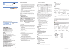
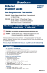
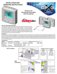
Wall Mount Installation
229150
Automatic
Digital Humidistat
Before Installing or Operating,
PLEASE READ ALL INSTRUCTIONS
In Automatic Mode, the Braeburn 229150 Digital Humidistat
will adjust humidity based on the outdoor temperature,
lowering the humidity in cold weather to reduce
condensation. The humidistat can operate in Manual Mode
to control humidity to a specific relative Humidity. In most
dwellings, Automatic operation is preferred to reduce
condensation on windows and within the structure.
Manual mode is necessary where the outdoor temperature
sensor cannot be installed. Manual mode may be desirable where valuable artwork, instruments
or woodwork demand constant humidity. The LCD Display is backlit and easy to read. The
humidistat can be mounted on an interior wall or on the return duct of the HVAC System.
This Humidistat must be installed by a Qualified Technician. Always turn off power to the HVAC
system prior to installing or servicing the humidifier or humidistat. Improper operation can
result in over or under humidification. Over humidification can result in condensation, structural
damage or mold. Condensation within a building’s structure can cause a loss of structural
strength. Condensation can also enable mold and mildew growth resulting in personal injury
and damage to building structure and contents. Older and poorly insulated structures cannot
withstand the same humidity levels as newer well insulated buildings. Read these instructions
carefully. This humidistat requires a 24 volt, AC power supply. Improper voltage can cause
malfunction or damage to the control. The technical specifications for this product and the
contents of the user manual are subject to change without notice.
Specifications
OPENING
FOR WIRES
BASE WITH VENTS
(FOR WALL MOUNT)
1.If installing the optional outdoor remote
sensor, choose a location on the north or
east wall of the structure. Install above
the snow line away from air intakes or
exhaust sources.
2. Run two wire (22 gauge minimum) cable
from the humidistat SNSR1 and SNSR2
terminals to the outdoor location. Attach
wire to sensor regardless of polarity. Wire run should not exceed 200 ft.
3.Install the metal hanging bracket with the screws provided. Insert sensor into large
opening of bracket and sensor wire into small opening of bracket.
4. Use non-hardening caulk to plug any wiring holes after verifying operation of sensor.
Wiring
WIRING TO 24 VAC HUMIDIFIER
WIRING TO FAN POWER HUMIDIFIER
SNSR 1
SNSR 2
HUM1
HUM2
AC N
AC L
Outdoor Temp.
-10˚F, (-23˚C) min
Accuracy RH 10%-90% +3% RH
Accuracy Indoor Temp. +1˚F, +1˚C
Accuracy Outdoor Temp. +1˚F, +1˚C
Resolution
1˚ or 1%
Outdoor Sensor
Constant
24 Volts
Constant
24 Volts
24 Volts
Switched
w/Furnace
Operation
Duct Mount Installation
IMPORTANT: Use base without vents for
duct mount installation.
1. Choose an accessible location on the
main RETURN air duct at least 15 inches
from any duct bends.
2. Drill a 1 inch diameter hole in the center
of your desired mounting location.
3. Using the base as a template, mark
two mounting holes and rectangular MOUNTING
opening (for wires).
HOLES (2)
4.Using a 1/8 inch drill bit, drill two
NO
mounting holes. Cut or drill out
VENTS
rectangular opening for wires.
5.Secure base to the duct with supplied
sheet metal screws. Pull wires
through opening.
6. Connect wires (see “wiring”) and then
attach humidistat body to base.
PUSH BASE
INTO 1”
HOLE IN
WALL
Remote Sensor Installation
SNSR 1
SNSR 2
HUM1
HUM2
AC N
AC L
Auto Mode
Control Range 10%-60% RH
Manual Mode
Control Range 10%-75% RH
WALL
IMPORTANT: Keep remote sensor wires at
least 6 inches from line voltage wires.
PRECAUTIONS
Electrical Rating 18-30 VAC, 60Hz
Switching Load 1 amp max.
Outdoor Sensor 200 ft. max.
IMPORTANT: Use base with vents for
wall mount installation.
1.Choose a location in the living area
that is clear of drafts or excessive
amounts of humidity. Avoid mounting
near air ducts, doors or windows.
Do not install in bathrooms or kitchens.
2. Drill a 1 inch diameter hole in the center
of your desired mounting location.
3. Using base as a template, mark the MOUNTING
two mounting holes and rectangular HOLES (2)
opening (for wires).
VENTS
4. Using a 3/8 inch drill bit, drill two
mounting holes and gently tap in
supplied anchors. Cut or drill out
rectangular opening for wires.
5.Secure base to the wall with supplied
plastic anchors and screws. Pull wires
through opening.
6. Connect wires (see “wiring”) and then
attach humidistat body to base.
Yellow
Yellow
120 Volts
Switched
w/Furnace
Operation
Quick Reference
DUCT
PLACE BASE
OVER 1”
HOLE IN
DUCT
OPENING
FOR WIRES
BASE WITHOUT VENTS
(FOR DUCT MOUNT)
DROP Button: Scrolls through Manual, Automatic and Off modes
THERMOMETER Button: Scrolls through indoor humidity (default), indoor temperature and outdoor temperature (if outdoor sensor is connected).
F˚ / C˚ F˚ / C Button: Used to select Fahrenheit or Celsius display mode.
DOWN and UP Buttons: Use to adjust settings up or down.
+
Buttons: Press the DROP and THERMOMETER buttons at the same time for 5 seconds.
The humidistat will enter the TEST mode. (see “Testing the System”)
+
Buttons: Press the DOWN and UP buttons at the same time to enter OFFSET mode
(see”OFFSET”).
“House” Symbol: Indoor temperature indicator.
“Tree” Symbol: Outdoor temperature indicator.
“Bar” Symbol: Humidity index indicator (Automatic Mode Only).
Testing the System
Display a Temperature
1. Re-assemble system and check all connections.
2. Restore power to the HVAC system.
3. Check to see that humidistat display is on.
4. Start HVAC System by raising thermostat setting in heat mode.
5. Set humidistat to TEST MODE by pressing the DROP and THERMOMETER buttons at the
same time for 5 seconds. The relay will close and the will flash for 2 minutes. The humidifier should start operation.
6. Set to OFF mode to verify humidifier operation ceases.
7. The humidistat will stay in OFF mode unless set to Manual or Automatic mode. See “Operation”.
Press the THERMOMETER button to move between displaying indoor and outdoor
temperature. The “tree” symbol will be displayed when showing outdoor temperature (if
outdoor sensor is connected). The “house” symbol will be displayed when showing indoor
temperature. To change between ˚F and ˚C, press the ˚F / C˚ button.
Operating Modes
Press any button to light the display. Press the DROP button to select Off, Manual or Auto Mode.
OFF Mode: The humidifier is turned off.
MANUAL Mode: The humidistat will maintain the single humidity Outdoor Suggested
Temperature Setting
set point selected. You can set your desired humidity level by
pressing UP or DOWN. The humidifier will turn ON or OFF
-20˚F -29˚C
15%
according to your setting. The humidifier will operate when the
-10˚F -23˚C
20%
measured relative humidity falls more than 1% below the set
0˚F -18˚C
25%
point until the measured relative humidity is 1% above the
+10˚F -12˚C
30%
set point. When the humidifier is operating, the will appear in
+20˚F -7˚C
35%
the display. Humidity may have to be lowered when weather is
+30˚F -1˚C
40%
colder or if condensation is suspected. The settings table at right
may be used for manual humidistat control.
AUTO Mode: The humidistat will automatically raise the humidity as the outdoor temperature
increases. This provides the highest possible humidity. The humidistat will automatically lower
the humidity as the temperature drops. This minimizes the risk of condensation on cold surfaces like windows. In AUTO mode only, the Auto Humidity Index Set Point may be changed.
You can set your desired humidity index from 0 (low) to 10 (high) by pressing UP or DOWN.
The Humidity Index is based on the outdoor temperature and indoor humidity. The humidifier will switch ON/OFF according to the calculated auto humidity index set point. When the
humidifier is operating, the will display. Lower Index settings are for older homes with less
insulation and poor vapor barriers. Higher Index settings are for newer homes with complete
vapor barriers, triple pane windows and high R value insulation.
Humidity Dwelling Type
Index
1-2
Older than 1950, no vapor barrier, little insulation.
3-4
Built 1950-1965, no vapor barrier, R6 insulation.
5-6
Built in 1965-1975, craft vapor barrier, R11 insulation.
7-8
Built in 1980-1990, craft vapor barrier, R19, double pane windows.
9-10
Built after 1990, poly vapor barrier, R38 insulation, foam exterior cladding, triple pane windows.
If condensation is seen or suspected, reduce humidity index by 2 until condensation stops.
The level bars in the upper right portion of the display indicate the humidity index; one bar for
every two index points. For example, a humidity index of 6 will have three bars displayed in
the upper right corner of the display.
AUTO Mode Target Humidity
Humidity
Index
1
2
3
4
5
6
7
8
9
10
-20
0
0
0
0
0
0
0
0
0
0
-10
5
8
11
14
17
20
23
26
29
32
0
10
13
16
19
22
25
28
31
34
37
Outdoor Temperature °F
10
20
15
20
18
23
21
26
24
29
27
32
30
35
33
38
36
41
39
44
42
47
30
25
28
31
34
37
40
43
46
49
52
40
30
33
36
39
42
45
48
51
54
57
50
35
38
41
44
47
50
53
56
59
62
% Relative Humidity
Trouble Shooting
“house” symbol flashing: The indoor temperature sensor has failed.
“tree” symbol flashing: The outdoor temperature sensor has failed.
Humidifier Turns On and Off Repeatedly
- Check that input voltage is between 18 and 30 volts AC and not intermittent.
- Check that humidistat is NOT mounted on supply duct, downstream of the humidifier
or within 12 inches of the humidifier.
- Make sure that Outdoor Sensor wiring is not close to line voltage wires.
Humidifier Runs Continuously
- If humidifier operates while HVAC system is off, check that power to humidifier is
switched with HVAC operation.
- If humidifier operates every time HVAC system runs, compare humidity to set point. If humidity is lower than set point, humidistat will call for operation.
Humidifier Does Not Run
-Check wiring to / from humidistat control. Verify 18-30 volts. Use TEST MODE (see
“Testing the System”).
Humidifier Runs When Air Conditioning is On
-If this is undesirable, change wiring to be powered only during heating periods, or set
humidistat to Off mode.
Humidity Not High Enough
- Fault with humidifier. Check humidifier, water supply, electrical connections.
- HVAC operating time is too short. Check humidifier trouble shooting.
- Humidifier is undersized. Review humidity load and humidifier capacity.
- Humidity index is set too low in Auto Mode (see “Auto Mode”).
Humidity Too High
- Wiring fault. Set humidistat to “OFF” mode and check that operation ceases.
- Outdoor sensor is being kept warm. Check that sensor is not buried in snow, on south side of house being warmed by sun or is too far inside of air intake.
- Humidity index set too high for structure.
Five Year Limited Warranty
Braeburn Systems LLC warrants each new Braeburn digital humidistat against any defects
that are due to faulty material or workmanship for a period of five years after the original
date of purchase by a professional service technician. This warranty and our liability does
not include damage to merchandise or the humidistat resulting from accident, alteration,
neglect, misuse, improper installation or any other failure to follow Braeburn installation
and operating instructions.
Braeburn Systems LLC agrees to repair or replace at its option any Braeburn digital
humidistat under warranty provided it is returned postage prepaid to our warranty facility
in a padded carton within the warranty period, with proof of the original date of purchase
and a brief description of the malfunction. This limited warranty does not include the cost
of removal or re-installation.
This warranty gives you specific legal rights and you may also have other rights that vary
from state to state or province to province. Answers to any questions regarding our limited
warranty may be obtained by writing our corporate offices.
WARRANTY FACILITY:
Braeburn Systems LLC
Attn: Warranty Department
2215 Cornell Avenue
Montgomery, IL 60538
OFFSET Mode
To change the calibration of the humidistat, an offset may be entered to the Humidity, Indoor
Temperature or Outdoor Temperature displays. Press both UP and DOWN buttons together to
enter OFFSET mode. The word OFFSET and RH will display. Press UP OR DOWN to change the
humidistat’s Humidity calibration. Press both UP and DOWN buttons together again to change
the Indoor Temperature offset. Press both UP and DOWN buttons together again to change
the Outdoor Temperature offset.
Braeburn Systems LLC
2215 Cornell Avenue • Montgomery, IL 60538
Technical Assistance: www.braeburnonline.com
Call us toll-free: 866-268-5599 (U.S. Only)
630-844-1968 (Outside the U.S.)
©2009 Braeburn Systems LLC • All Rights Reserved • Made in China
229150-100-002
5
YEAR
LIMITED
WARRANTY