1
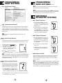
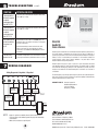
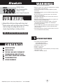
WARNING!
Important Safety Information
MODEL
1200
Builder Series
Non-Programmable
2 Heat / 1 Cool
Heat Pump Thermostat
USER MANUAL
Compatible with low voltage multi-stage heat
pump systems with up to two stages of heating
and one stage of cooling. Not for use on
single-stage heating or cooling systems.
• Always turn off power to the air conditioning or heating system prior to installing,
removing, cleaning or servicing thermostat.
• Read this manual thoroughly prior to installing, programming or operating
this thermostat.
• This thermostat is designed for use with a 24 Volt-AC low voltage multi-stage
heat pump systems.
• Do not use this thermostat on single stage systems or other systems with
voltages higher than 30 Volt-AC.
• This thermostat requires 24 Volt AC power for normal operation and control of
the heating or cooling system.
• Wiring must conform to all building codes and ordinances as required by local
and national code authorities having jurisdiction.
• Do not short (or jumper) across terminals at the heating or cooling system
control board to test the thermostat installation. This could damage the
thermostat and void the warranty.
• Do not select COOL mode of operation if the outside temperature is below 50˚ F
(10˚ C). This could possibly damage the controlled cooling system and may
cause personal injury.
• This thermostat should only be used as described in this manual. Any other use
is not recommended and will void the warranty.
READ ALL INSTRUCTIONS BEFORE PROCEEDING
1
CONTENTS
1 SPECIFICATIONS
2 INSTALLATION
3 TESTING YOUR NEW THERMOSTAT
4
5
6
7
SPECIFICATIONS
• Electrical Rating: 24 Volt AC (18-30 Volt AC)
1 amp maximum load per terminal
3 amp total maximum load (all terminals)
• Control Range: 45˚ - 90˚ F (7˚ - 32˚ C)
• Accuracy: +/- 1˚ F (+/- .5˚ C)
• AC Power: 18-30 Volt AC
• Compatibility: Multi-stage heat pump systems with up to two stages of heating
and one stage of cooling.
• Terminations: R, C, G, Y, W2, E, O, and B
PROGRAMMING USER SETTINGS
ADDITIONAL OPERATION FEATURES
TROUBLESHOOTING
WIRING DIAGRAMS
© 2004 Braeburn Systems LLC • Patents Pending • All Rights Reserved.
Pub. No. 1200-100-006
1
2
INSTALLATION
2
INSTALLATION
2.1
Replacing Existing Thermostat
2.2
Installing Your New Thermostat cont.
1. Always turn off power to the air conditioning or heating system prior to removing
existing thermostat.
2. Remove the cover of your old thermostat and locate the wire terminals. Do not remove
wires from terminals yet.
3. Using small pieces of masking tape label wires prior to removal from terminals. Use
the chart below to determine the new terminal designations for your new thermostat.
Old Terminal from
Existing Thermostat
R, V-VR or VR-R
O
B
C, X or B
Y, Y1 or M
E
G or F
W1, W2 or W-U
10. Fasten the sub-base to wall using supplied screws.
11. Connect wires to quick wiring terminal block as appropriate using the new terminal
designations. Refer to Wiring Diagram section of this manual if required for assistance.
12. Make sure all of the wire connections are secure and are not touching any other
terminal to prevent electrical shorts and potential damage to the thermostat.
13. Turn the front thermostat body over, exposing the rear view of the circuit board.
New Terminal for
New Thermostat
Terminal Description
14. Locate the interal ˚F / ˚C switch on the circuit board.
R
O
B
C
Y
E
G
W2
24 VAC
Reverse Valve (Cooling)
Reverse Valve (Heating)
24 VAC common
1st Stage Compressor
Emergency Heating
Fan Control
2nd Stage / Aux Heating
15. Using your fingers, gently flip the switch toward the preferred temperature ˚F / ˚C scale.
4. After labeling and removing all wires from terminals, unscrew the existing thermostat
sub-base from wall. Make sure to secure wires to prevent them from slipping back
into the hole in the wall.
NOTE:
This thermostat is for use on low voltage 24 Volt AC multi-stage heat pump
systems with up to two stages of heating and one stage of cooling and requires a
transformer common wire for proper installation. This thermostat is not for use on
single stage heating or cooling systems.
2.2
cont.
Installing Your New Thermostat
NOTE:
If you are installing this thermostat in a new installation be sure to locate
the thermostat 4 to 5 feet above the floor in accordance with applicable building
codes. Make sure to install the thermostat in a location that provides good airflow
characteristics and avoid areas behind doors, near corners, air vents, direct sunlight
or near any heat generating device. Installation in any of these areas could impact
thermostat performance.
1. Always turn off power to the air conditioning or heating system prior to installing your
new thermostat.
2. Place system switch on front of thermostat to OFF position.
3. Place fan control switch on front of thermostat to AUTO position.
4. Remove front of thermostat body from sub-base by pressing release latch on bottom
of front body.
5. Place the thermostat sub-base against wall in the desired thermostat location.
6. Guide thermostat wires through center hole in sub-base. Continue to hold sub-base
against wall.
7. Mark placement of mounting holes as appropriate and drill using a 3/16" drill bit.
8. Gently tap supplied plastic anchors into the holes in the wall.
9. Place the thermostat sub-base against the wall in the desired location, making sure
the mounting holes are aligned as appropriate and the thermostat wires are properly
inserting through opening in middle of sub-base.
16. Attach front body of thermostat to sub-base of thermostat, being careful to align
the terminal pins on the front body with the terminal block on the sub-base.
17. Restore system power so you can test installation.
3
TESTING YOUR
NEW THERMOSTAT
WARNING! Read BEFORE Testing
• Do not short (or jumper) across terminals at the heating or cooling system
control board to test the thermostat installation. This could damage the thermostat
and void the warranty.
• Do not select COOL mode of operation if the outside temperature is below 50˚ F
(10˚ C). This could possibly damage the controlled cooling system and may
cause personal injury.
• This thermostat includes an automatic compressor protection feature to avoid
potential damage to the heat pump system from short cycling. This thermostat
automatically provides a 5-minute delay after turning off the heating or cooling
heat pump output to protect the compressor.
NOTE:
Test your thermostat prior to programming any user settings. Pressing the
RESET button will erase any user entries previously programmed. This will erase all
user settings and return them to their default values.
1. Place the system switch in the HEAT position.
2. Press the button on the keypad until the setpoint temperature setting is a minimum of 3 degrees
higher than the current room temperature. The heating system should start within several
seconds. The fan may not turn on immediately due to the heating system built-in fan delay.
3. Place the system switch in the OFF position. The heating system should stop within
several seconds.
4. Wait 5 minutes for the automatic compressor short cycle protection period to expire, or press the
RESET button to bypass this feature for initial testing purposes. Pressing the RESET button will
erase any user entries previously programmed.
5. Place the system switch in the COOL position.
6. Press the button on the keypad until the setpoint temperature is a minimum of 3 degrees lower
than the current room temperature.
7. The cooling system should start within several seconds. Place the system switch in the OFF
position. The cooling system should stop within a few seconds.
8. Place the fan switch in the ON position. The system blower should start.
9. Place the fan switch in the AUTO position. The system blower should stop.
2
3
4
PROGRAMMING
USER SETTINGS
4
4.1
Default Thermostat Settings
NOTE:
Function
Operation Mode
Room Temperature
Setpoint Temperature
Temperature Scale
First Stage Differential
Second Stage Differential
Short Cycle Protection Timer
Output Relays
4.2
Once you have finished setting the differentials, wait 5 seconds and the
thermostat will return to the normal operating mode.
Status After Reset
Normal Operating Mode
70˚ F (21.0˚ C), to be renewed within
5 seconds
According to system switch:
62˚ F (17.0˚ C) for Heat,
Emergency Heat and Off
85˚ F (29.0˚ C) for Cool
˚F or ˚C dependent on switch setting
0.5˚ F (0.25˚ C)
2˚ F (1.0˚ C)
Reset
Off
NOTE:
To erase all user program settings, gently press RESET button using a paper
clip or a small pencil tip. This will return all thermostat settings to their default values.
Remember, this will erase all user program settings entered by the user.
5
ADDITIONAL
OPERATION FEATURES
5.1
Review Set Temperature
1. Press and hold the or buttons. The current
setpoint temperature will be displayed in the place
of the current room temperature, and the indicator
SET will be displayed.
Setting Temperature Differential
The default settings for the first and second stage differentials and residual cooling fan delay
settings are compatible with most systems and applications. This is normally set at time of
installation and usually does not require any modification under normal operating conditions.
If you feel that the first or second stage of your system is turning on too often, simply follow the
instructions below.
NOTE:
The first and second stage differential settings are the same for the
heating system.
4.2.1 Setting First Stage Differential
The default setting is 0.5˚ F (0.25˚ C). The room temperature must change .05˚ F (0.25˚ C) from
the setpoint temperature before the thermostat will initiate the system in heating or cooling.
2. The display will return to normal operating mode
when the or button is released. Continuing
to hold the or button for 3 seconds or longer
will allow the user to change the current setpoint
temperature (See Changing Set Temperature).
5.2 Changing Set Temperature
1. Press and hold or button for 3 seconds. The
entire display will flash once and the SET indicator
will be flashing. Release the or button and
press the or button again as desired to adjust
the set temperature.
2. The display will return to normal operating mode
after 5 seconds.
1. In normal operating mode, press and hold the
and buttons at the same time for 4 seconds.
LCD display will show "SET D1 x˚", where "x"
equals the ˚F / ˚C differential setting. This is the
current first stage differential setting.
3. The SET indicator will turn off indicating that the
current temperature shown in the display is the
room temperature.
2. Press the or buttons to set the first stage
differential to your desired setting of .5˚, 1˚, or 2˚ F (.25˚––displayed as .2˚, .5˚, or 1˚ C).
NOTE:
If you do not desire to change the second stage differential "SET D2" setting you
can wait 5 seconds and the thermostat will automatically return to the normal operating
mode. Otherwise, you can press the and buttons at the same time twice to skip the
second stage differential setting.
5.3 Compressor Protection
This thermostat includes an automatic compressor protection feature to avoid potential
damage to the heat pump system from short cycling. This thermostat automatically
provides a 5-minute delay after turning off the heating or cooling heat pump output to
protect the compressor.
NOTE:
4.2.2 Setting Second Stage Differential
The default setting is 2˚ F (1.0˚ C). This means that the
room temperature must change 2˚ F (1.0˚ C) in addition
to the first stage differential setting before the thermostat
will initiate the second stage of the system in heating.
PROGRAMMING
USER SETTINGS cont.
2
The installer can reset the thermostat and bypass the compressor protection
features by pressing the RESET button. This will erase all user program settings and
should only be used during installation for testing purposes or to reset a thermostat to
regain normal operation. This will return all thermostat settings to their default values.
The user will have to re-program all of the erased settings.
3. Press the and buttons at the same time again
and the LCD display will show "SET D2 x˚", where "x"
equals the ˚F / ˚C differential setting. This is the current second stage differential setting.
4. Press the or buttons to set the second stage differential to your desired setting of 2˚, 3˚,
4˚, 5˚, or 6˚ F (1.0˚, 1.5˚, 2.0˚, 2.5˚, or 3.0˚ C).
4
5
5
ADDITIONAL
OPERATION FEATURES cont.
5.4 Resetting The Thermostat
The Reset feature allows the user to completely reset the thermostat and to register new
manual ˚F / ˚C temperature scale switch settings.
1. To erase all entered program settings, gently press RESET button using a paper clip or a
small pencil tip.
2. This will return all thermostat settings to their default values and register all new manual
˚F / ˚C temperature scale switch settings.
5.5 Non-Volatile Memory
In the event of a power failure, the Non-Volatile Memory feature of this unit allows all settings to
be recovered, eliminating the need to reset temperature and differential settings. When AC
power is restored after an outage, all settings are retrieved from memory and reinstated.
6
6
TROUBLESHOOTING cont.
SYMPTOM
POTENTIAL SOLUTION
Thermostat turns on
second (auxiliary)
stage of heating or
cooling too quickly or
not quickly enough.
Increase or decrease second (auxiliary) stage temperature
differential setting as appropriate to provide the desired
performance level. See Setting Temperature Differential.
OFF is shown in
thermostat display
and heating or
cooling system will
not start.
This indicates that the system is turned off at the thermostat.
Move the system selector switch to the HEAT or COOL position.
After the compressor short cycle protection 5-minute period
expires the system should start within several seconds.
Thermostat display
is blank.
It is possible that AC power is not present at the thermostat.
Check fuse, circuit breaker and thermostat wiring as appropriate
to verify AC power is available.
TROUBLESHOOTING
SYMPTOM
POTENTIAL SOLUTION
Thermostat does not
turn on heating or
cooling system.
Check to see if OFF is shown in display. This indicates that the
system is turned off at the thermostat. Move the system selector
switch to the HEAT or COOL position. After the compressor short
cycle protection 5-minute period expires the system should start
within a minutes time.
Compressor protection features may be in effect due to
compressor short cycle conditions. See Compressor Protection
section for full explanation of this feature.
Heat Pump may be malfunctioning. If heating is required, you
can slide the system switch to EMER setting, which will start
the Emergency Heat source to provide heating until the heat
pump can be serviced.
Thermostat turns
on heating instead
of cooling, or
cooling instead of
heating.
Check thermostat wiring to make sure that the heating and
cooling stages are connected to the correct terminals on the
wiring terminal block. See Installation and Wiring Diagram
sections of this manual.
Thermostat turns
heating or cooling
system on too often
or not often enough.
Increase or decrease first stage temperature differential setting
as appropriate to provide the desired performance level. See
Setting Temperature Differential.
If AC Power is present, call a professional service technician
immediately to verify thermostat and system performance.
HI is shown in the
thermostat display
where the room
temperature is
normally displayed.
The temperature sensed by the thermostat is higher than the
90˚ F (32˚ C) upper limit of the thermostats display range. The
display will return to normal after the sensed temperature
lowers within the 45˚ to 90˚ F (7˚ to 32˚ C) display range. Turn on
the cooling system or use other methods to lower the
temperature accordingly.
This condition could occur from the system being turned off
during an exceptionally warm period or upon installation when
the thermostat has been stored for a long period of time in a
warm vehicle or location prior to being installed. The thermostat
is equipped with a mechanical high temperature safety switch
that will turn off the thermostat should the temperature exceed
99˚ F (37˚ C).
LO is shown in the
thermostat display
where the room
temperature is
normally displayed.
The temperature sensed by the thermostat is lower than the
45˚ F (7˚ C) lower limit of the thermostats display range.
The display will return to normal after the sensed temperature
rises within the 45˚ to 90˚ F (7˚ to 32˚ C) display range. If the
temperature in the controlled space seems to be normal,
wait for the thermostat to acclimate to the correct room
temperature. If the room seems to be colder than usual, turn
on the heating system to raise the temperature as needed for
comfort within the room.
This condition could occur from the system being turned off
during a cold weather period or upon installation when the
thermostat has been stored for a long period of time in a cold
vehicle or location prior to being installed. The thermostat
should be allowed to warm up prior to installation to allow
proper heating control once installed.
6
7
6
TROUBLESHOOTING cont.
SYMPTOM
POTENTIAL SOLUTION
Thermostat will not
allow me to program
a setpoint
temperature higher
than 90˚ F (32˚ C).
This is above the normal thermostat temperature setting range
of 45˚ to 90˚ F (7˚ to 32˚ C).
Thermostat will not
allow me to program
a setpoint
temperature lower
than 45˚ F (7˚ C).
This is below the normal thermostat temperature setting range
of 45˚ to 90˚ F (7˚ to 32˚ C).
Fan continues to run
all the time whether
the system is on
or off.
Check that the fan control switch is in the AUTO position. This
will allow the fan to run only when the heating or cooling system
is turned on and running.
The room is too
warm or too cold.
See Review Set Temperature section of this manual to verify the
current setpoint and make any modifications that are necessary.
7
Check thermostat wiring to make sure that the fan control
wiring is connected to the correct terminals on the wiring
terminal block. See Installation and Wiring Diagram sections of
this manual.
B
Changeover
Relay - Heat
C
Y
Transformer Common
(Required)
O
G
E
Emergency
Heat Relay
Braeburn Systems LLC warrants each new Braeburn thermostat against any defects that are
due to faulty material or workmanship for a period of five years after the original date of
purchase by a professional service technician. This warranty and our liability does not apply to
batteries, nor does it include damage to merchandise or the thermostat resulting from
accident, alteration, neglect, misuse, improper installation or any other failure to follow
Braeburn installation and operating instructions.
Braeburn Systems LLC agrees to repair or replace at its option any Braeburn thermostat
under warranty provided it is returned postage prepaid to our warranty facility in a padded
carton within the warranty period, with proof of the original date of purchase and a brief
description of the malfunction. This limited warranty does not include the cost of removal or
re-installation.
WIRING DIAGRAM
Wiring Diagram for 2 Stage Heat, 1 Stage Cool
R
Store this
booklet for
future reference
This warranty gives you specific legal rights and you may also have other rights that vary from
state to state or province to province. Answers to any questions regarding our limited warranty
may be obtained by writing our corporate offices.
W2
WARRANTY FACILITY: Braeburn Systems LLC
Attn: Warranty Department
2215 Cornell Avenue
Montgomery, IL 60538
Auxiliary Heat
Relay (Stage 2)
See Note 1
Changeover
Relay - Cool
Compressor
Contact
Fan Relay
Neutral
24 VAC
120 VAC
Hot
NOTE:
1. Jumper is required to use Auxiliary Heat for both Second Stage and
Emergency Heat on units without separate Emergency Heat and Auxiliary
Heat terminals.
2. Make O / B connections as required by unit.
8
Braeburn Systems LLC
2215 Cornell Avenue • Montgomery, IL 60538
Technical Assistance: www.braeburnonline.com
Call us toll-free: 866-268-5599 (U.S. Only)
630-844-1968 (Outside the U.S.)
© 2004 Braeburn Systems LLC • Patents Pending • All Rights Reserved. Pub. No. 1200-100-006