1
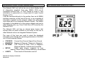
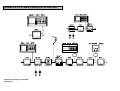
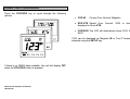
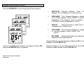
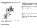
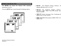
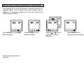
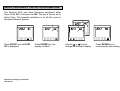
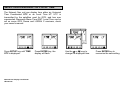
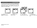
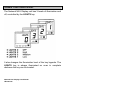
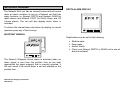
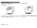
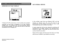
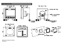
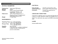
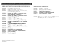
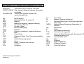
CONTENTS
CONTENTS..............................................................................1
USING THE LIGHTS KEY..................................................... 16
GENERAL INTRODUCTION TO B&G NETWORK ...............2
INTRODUCTION TO NETWORK NAV...................................3
NETWORK NMEA INTERFACING RULES ...........................5
SYSTEMS WITH MULTIPLE NAV UNITS..............................5
INTERFACING NETWORK NAV AND PILOT .......................6
EXAMPLE SYSTEMS USING NETWORK NAV ....................7
NETWORK ALARMS............................................................ 17
FAULT AND ERROR MESSAGES ...................................... 19
USING THE COG/SOG KEY...................................................8
SPECIFICATION ................................................................... 22
NAV NMEA 0183 (v1.5) SENTENCE SUMMARY............... 23
USING THE BTW/DTW KEY...................................................9
USING THE OPTIONS KEY..................................................10
INSTALLATION..................................................................... 20
SITING THE UNIT ................................................................ 20
MOUNTING THE UNIT......................................................... 20
GLOSSARY AND ABBREVIATIONS .................................. 24
USING THE SETUP KEY ......................................................11
SELECTING TRUE OR MAGNETIC BEARINGS ................12
SELECTING GREAT CIRCLE OR RHUMB-LINE ...............13
SELECTING UNIVERSAL OR LOCAL TIME.......................14
SELECTING THE NMEA DATA 183/180 .............................15
Network Nav Display User Manual
HB-0523-02
1
GENERAL INTRODUCTION TO B&G NETWORK
The B&G Network range of instruments is designed for use as
individual units or connected together to form an integrated
navigational system. A single network cable is used to carry
data and power between units. The latest technology and
screened cables throughout the Network System ensure the
ultimate protection from interference between units and other
systems. All Network instruments can be linked to Network
PILOT, Network CHART, Network GPS or Network LORAN
receivers or via NMEA 0183 (v1.5) to other navigational
equipment.
INSTRUMENTS
NAVIGATIONAL AIDS
Network SPEED
Network DEPTH
Network QUAD
Network WIND
Network TACK
Network DATA
Network GPS
Network LORAN
Network NAV
Network CHART
AUTOPILOTS
COMMUNICATIONS
Network PILOT
Network VHF
Network Nav Display User Manual
HB-0523-02
2
INTRODUCTION TO NETWORK NAV
NETWORK NAV DISPLAY UNIT
The Network NAV unit will act as an on-deck display head
of information supplied from any NMEA 0183 (v1.5)
compatible position fixer, i.e. GPS, Decca or Loran C. This
information is presented on a large back-lit Liquid Crystal
Display (LCD).
It can be connected directly to the position fixer via its' NMEA
interface connector, at the rear of the unit, or as a repeater of
information supplied via the network cables from other NAV
units when part of an integrated Network System. The NMEA
information is translated on to the system network and sent to
other Network units, e.g. Cross Track Error (XTE) used by the
Network PILOT.
The Network NAV unit has an internal alarm buzzer that
sounds when an alarm condition is met either on the unit or
other Network units in an integrated Network System.
The rows of five keys are used to select the displayed
information and change the operating parameters of the NAV
unit. A brief summary follows:
•
•
•
•
•
COG/SOG
BTW/DTW
OPTIONS
Course Over Ground, Speed Over Ground
Bearing to Waypoint, Distance to Waypoint
XTE, Course to Steer, Time to Waypoint,
Waypoint Identity, Latitude and Longitude
SETUP
Select data source, magnetic or true
bearing, Great Circle or Rhumb distance, Arrival Alarm
LIGHTS
Three levels of illumination and off.
Network Nav Display User Manual
HB-0523-02
3
INTRODUCTION TO NETWORK NAV
IMPORTANT NOTE
It is important to remember that the Network NAV unit is only
a display head for any compatible position fixer. Any erratic or
positional errors generated by the position fixer due to poor
reception, bad satellite constellation or radio beacon chain
transitions, will be displayed on the Network NAV and also
transmitted to your Network PILOT, if the NAV is part of a
system containing an autopilot. It is strongly recommended
that an accurate log and positional plot be maintained on a
current chart.
Before using Network NAV for navigation or supply of data to
Network PILOT, check the following:
• The position fixer has a compatible NMEA 0183 (v1.5)
interface, set-up and connected in accordance with the
manufacturers' instructions.
• It is switched on and has the correct current position.
• The signal and noise levels are
manufacturers' recommended levels.
within
the
• The waypoints have been entered correctly, and the
waypoint arrival alarm switched on (if it has one).
• If using waypoints in a Route or Sail (cruise) Plan, they
are entered correctly and the route is enabled.
Network Nav Display User Manual
HB-0523-02
4
NETWORK NMEA INTERFACING RULES
SYSTEMS WITH MULTIPLE NAV UNITS
The following rules apply to all Network Systems interfacing
with any NMEA 0183 (v1.5) device, e.g. GPS, Decca, Loran
C, and Chart Plotters.
The Interfacing Rules described previously must be
appreciated when using multiple Network NAV units in an
Network System. Additionally the following applies:
• There can only be one of each of the following position
fixer types connected to a Network System:
• GPS, Decca and Loran C.
• Up to four NAV units may be fitted on a Network
System. A NAV unit connected to a position fixer
automatically acts as the master unit, any other units
NOT connected to position fixers, act as repeaters.
• The Network System only allows one source of
information for any given NMEA function, transmitted
onto the network, e.g. there can be only one XTE
supplied from the device selected.
• When a Network System contains a Network PILOT,
with a display head, and a Network NAV unit, the NMEA
input on the Network PILOT display head CANNOT be
used.
• When the Network PILOT is engaged it is NOT possible
to change the source of NMEA information, e.g. it is not
possible to change from GPS to Loran C (or Decca)
without disengaging the Network PILOT.
Network Nav Display User Manual
HB-0523-02
• It is possible for a Network System to contain more than
one master NAV unit, i.e. one could be connected to a
GPS and another to a Decca (or Loran C). When a NAV
unit is connected to a position fixer it will declare its type
by transmitting a short message on to the system
network. GP = GPS, DC = Decca, LC = Loran C.
• As the Network rules only allow one source of NMEA
information the transmitting master NAV unit connected
to it's position fixer, must be selected using the SETUP
key. The type of position fixer selected is identified on
the LCD (Refer to Using The SETUP Key).
• Only one of each type of position fixer is allowed.
5
INTERFACING NETWORK NAV AND PILOT
IMPORTANT NOTE
• A Network System cannot be constructed where one
position fixer is connected via the PILOT display unit
NMEA input socket and another via the NAV unit
interface. This is an invalid configuration.
• If two (different) position fixers are required it is always
necessary to use two NAV units.
• The Network PILOT Display and Computer unit will use
NMEA information from whichever position fixer is
selected.
• The source of the NMEA information can only selected
using a NAV unit. The NAV1 and NAV2 options on the
Network PILOT display are no longer valid.
• If the NAV unit is to be added to an existing system
containing a Network PILOT display, interfaced to an
NMEA position fixer via the NMEA input, it will be
necessary to transfer the NMEA input from the PILOT
display to the NAV unit.
Network Nav Display User Manual
HB-0523-02
6
EXAMPLE SYSTEMS USING NETWORK NAV
Network Nav Display User Manual
HB-0523-02
7
USING THE COG/SOG KEY
Press the COG/SOG key to cycle through the following
options.
• COG M
Course Over Ground, Magnetic.
• SOG KTS Speed Over Ground, SOG is always
displayed in Knots KTS.
• COG/SOG The LCD will alternatively show COG, then
SOG.
COG can be displayed as Magnetic M or True T bearings,
selected using the SETUP key.
If there is no NMEA data available, the unit will display OFF
when the COG/SOG button is pressed.
Network Nav Display User Manual
HB-0523-02
8
USING THE BTW/DTW KEY
Press the BTW/DTW to cycle through the following options.
•
WPB GC M
Waypoint Bearing, Great Circle,
Magnetic. This is displayed for 5 seconds only.
•
WPB NAME Then Waypoint Bearing is displayed
to the target waypoint, where "NAME" is the first 4
characters of the waypoint name or number, e.g.
"JACKSON" would be displayed as "JACK".
•
WPD GC
Waypoint Distance, Great Circle. This
is displayed for 5 seconds only.
•
WPD NAME Then Waypoint Distance is displayed
to the target waypoint, where "NAME" is as
above.
•
B/D NAME
Bearing and Distance are alternatively
displayed to the target waypoint.
Waypoint Bearing can be displayed as Magnetic M or True T,
selected using the SETUP key.
If there is no NMEA data available, the display will show OFF
when the BTW/DTW button is pressed.
Network Nav Display User Manual
HB-0523-02
Waypoint Distance can be displayed as Great Circle GC or
Rhumb-line RH, selected using the SETUP key.
9
USING THE OPTIONS KEY
Use the OPTIONS key to cycle through the following options.
• WP NAME The identifying name or number of the
target waypoint, where "NAME" is the first 4 characters
of the waypoint name or number, e.g. "JACKSON"
would be displayed as "JACK".
• TTG HRS Time To Go to the target waypoint in hours.
• XTE
Cross Track Error, with steering indicator.
steer to port, steer to starboard.
• CTS M
waypoint.
Course To Steer, Magnetic M, to the target
• VMG NAME Velocity Made Good to "NAME".
• LAt/LOn Alternating display of present Latitude and
Longitude.
• UTC
Universal Time Coordinated, can also be
selected to display Local Time LT, if available from the
position fixer.
If there is no NMEA data available, the display will show OFF
when the OPTIONS key is pressed.
Network Nav Display User Manual
HB-0523-02
10
USING THE SETUP KEY
The SETUP key allows the Network NAV operating
parameters to be set.
• BRG M0
The displayed bearing reference, either
Magnetic M (factory set), or True T.
Press the SETUP key to cycle through the following options.
• DIST GC The displayed distance method of
calculation, either Great Circle GC (factory set), or
Rhumb Line RH.
• TIME UTC Selects Universal Time Coordinated UTC
(factory set), or Local Time LT.
• NMEA 183 NMEA Data selection NMEA 0183 (V1.5) or
NMEA 0180.
Network Nav Display User Manual
HB-0523-02
11
SELECTING TRUE OR MAGNETIC BEARINGS
The Network NAV can show bearing in degrees referenced to
Magnetic M or True T North. The unit is factory set to
Magnetic. The selected reference is for all Nav units on the
whole Network System.
Press SETUP key until BRG
M0 is displayed.
Network Nav Display User Manual
HB-0523-02
Press ENTER key, the
display will flash.
Use the S or T keys to
change the bearing
reference.
Press ENTER key to
memorise the new setting.
12
SELECTING GREAT CIRCLE OR RHUMB-LINE
The Network NAV can show Distances calculated either
Great Circle GC or Rhumb-Line RH. The unit is factory set to
Great Circle. The selected calculation is for all Nav units on
the whole Network System.
Press SETUP key until DIST
GC is displayed.
Network Nav Display User Manual
HB-0523-02
Press ENTER key, the
display will flash.
Use the S or T keys to
change the distance display.
Press ENTER key to
memorise the new setting.
13
SELECTING UNIVERSAL OR LOCAL TIME
The Network Nav unit can display time either as Universal
Time Coordinated UTC or as Local Time LT. UTC is
transmitted by the satellites used for GPS, and has now
superseded Greenwich Mean Time GMT. Local Time can be
set on some GPS, Decca and LORAN C receivers, check
your owner's manual.
Press SETUP key until TIME
UTC is displayed.
Network Nav Display User Manual
HB-0523-02
Press ENTER key, the
display will flash.
Use the S or T keys to
change the displayed time.
Press ENTER key to
memorise the new setting.
14
SELECTING THE NMEA DATA
This selection allows the NAV to translate early NMEA device
output sentences for display. Modern equipment uses NMEA
0183 output sentences, early equipment may have used
NMEA 0183. Consult the user manual for your equipment to
determine the correct setting
Press SETUP key until
NMEA 183 is displayed.
Network Nav Display User Manual
HB-0523-02
Press ENTER key, the
display will flash.
Use the S or T keys to
change the NMEA data type.
Press ENTER key to
memorise the NMEA data
type.
15
USING THE LIGHTS KEY
The Network NAV Display unit has 3 levels of illumination and
off, controlled by the LIGHTS key.
It also changes the illumination level of the key legends. The
LIGHTS key is always illuminated so even in complete
darkness the key can be located.
Network Nav Display User Manual
HB-0523-02
16
NETWORK ALARMS
DEPTH ALARM DISPLAY
The Network NAV unit has an internal buzzer that will sound
when an alarm condition is met on a Network unit that has
alarm functions i.e. Network DEPTH and Network QUAD for
depth alarms and Network PILOT for Watch Alarm and Off
Course alarms. The unit will also display which alarm is
activated.
To silence the internal alarm and return the display to normal
operation press any of the five keys.
WAYPOINT ARRIVAL
Depth alarms can be set for the following:
•
•
•
•
Shallow water
Deep water
Anchor Watch
Check your Network DEPTH or QUAD unit to see which
alarm is activated.
The Network Waypoint Arrival alarm is activated when an
alarm signal is sent from the position fixer as the boat
approaches the target waypoint that is currently selected. It
will only sound if the arrival alarm is set and enabled on the
position fixer.
Network Nav Display User Manual
HB-0523-02
17
NETWORK ALARMS
NETWORK PILOT ALARM DISPLAYS
OFF-COURSE ALARM
WATCH ALARM
The Watch Alarm is a count-down timer which is activated at
the end of the preset count-down period. The display
alternates between the messages above.
Network Nav Display User Manual
HB-0523-02
The Off Course alarm is activated when the boat deviates off
course by a preset amount. The display alternates between
the messages above.
18
FAULT AND ERROR MESSAGES
UNIT INTERNAL ERRORS
NETWORK PILOT FAULT DISPLAY
If Network PILOT should have a fault condition the autopilot
computer unit will send a message to all other Network
Display Units. The Network NAV unit will alternately display
the following message, the actual fault will have to read from
the Network PILOT Display unit.
In the unlikely event that your Network NAV unit should
develop an internal error, the unit will sound its alarm
continuously and the display will show an error number.
Pressing the keys will not silence this alarm.
In some cases the fault can be cleared by switching off the
instruments at the supply, waiting a few moments and then
switching on again. If this does not clear the fault the error
number should be recorded.
Switch off the supply and disconnect the faulty unit. Return it
with the error number to your dealer for servicing.
Network Nav Display User Manual
HB-0523-02
19
INSTALLATION
MOUNTING THE UNIT
The display heads are supplied with a clip-in mounting
bracket that allows for easy installation, access from behind is
not necessary to secure the unit in place. However to prevent
theft and permanently fix the unit in position, locking studs
and thumb nuts are supplied.
Use the cutting template supplied to mark the centres of the
holes for the self-tapping screw, the fixing stud holes and the
mounting bracket.
SITING THE UNIT
All Network Instruments are designed for mounting on or
below deck. A mounting position should be selected where
they are:
•
•
•
•
Easy to read by the helmsman
On a smooth and flat surface
At least 100mm (4") from a compass
Accessible from behind for fitting locking studs if
required.
Network Nav Display User Manual
HB-0523-02
• The template allows 4mm (5/32") between adjacent
units for the sun cover, increase this distance if required
to maximum of 60mm (2 3/8") between units or 180mm
(3 1/8") between centres. For greater distances
between units extension cables are available.
• Use a 70mm (2 3/4") diameter hole-cutter for the
mounting bracket hole.
• Use a 2.9mm for the self-tapping screw holes.
• Use a 5mm (3/32") drill for the locking stud holes.
• Secure the mounting bracket to the bulkhead with the
self-tapping screws supplied
• Fit the rubber-sealing gasket around the mounting
bracket.
• Screw the locking studs into the back of the display
head (if required).
• Carefully pass the cable tails through the mounting
bracket hole, connect the cables to the main units.
• Clip the display head into the mounting bracket.
• Secure the instrument with the thumb nuts supplied.
20
INSTALLATION
Network Nav Display User Manual
HB-0523-02
21
SPECIFICATION
PHYSICAL PARAMETERS
ELECTRICAL
Construction
Window
Display
Power Supply
Operating Current
Protection
Dimensions
Weight
High impact ABS plastic
Acrylic
Back-lit Liquid Crystal Display:
Large Digits: 28.6mm 1.12"
Small Digits: 11.5mm 0.45"
110 x 110 x 25.4mm 4 x 4 x 1"
Requires 65mm 2.6" depth behind
bulkhead for display barrel
0.3 kg 0.66lbs
ENVIRONMENTAL
Operating Temp -10 to +550C @ 93%RH
+14 to +1310F @ 93%RH
Storage Temp -25 to +700C @ 95%RH
-13 to +1580F @ 93%RH
Humidity
Up to 95%RH
Sealing
Fully sealed front, suitable for bulkhead
cockpit mounting. Vented barrel to
prevent condensation.
Network Nav Display User Manual
HB-0523-02
12V DC nominal (10V to 16V)
40mA typical, 100mA illuminated
Connect via external fuse or
circuit breaker.
CABLES AND CONNECTIONS
Connection to adjacent units is via cable tails fitted with either
a plug or a socket. Extension cables are available from your
dealer. The cable tails carry power and NMEA data between
units.
ALARM
Internal audible alarm
22
NAV NMEA 0183 (v1.5) SENTENCE SUMMARY
NMEA INPUT SENTENCE (NETWORK DECODED DATA)
NMEA OUTPUT SENTENCES
$IDAAM
$IDAPA
$IDAPB
$IIHDM
$IIVHW
$IIDBT
$IIVWR
$IIMTW
$IDBWC
$IDBWR
$IDGLL
$IDGGA
$IDGLP
$IDRMA
$IDRMB
$IDRMC
$IDVHW
$IDVTG
$IDWCV
$IDXTE
$IDZTG
Arrival alarm, waypoint i.d.
XTE, arrival alarm, waypoint i.d.
XTE, bearing to waypoint, course to steer,
arrival alarm, waypoint i.d.
Bearing and distance to waypoint, great
circle measured, waypoint i.d.
Bearing and distance to waypoint, rhumb
measured, waypoint i.d.
Latitude, Longitude.
Latitude, Longitude (GPS only).
Latitude, Longitude, waypoint id (Loran).
Latitude, Longitude, SOG, COG, variation
(Loran).
XTE, bearing and distance to waypoint,
VMG to waypoint, waypoint i.d.
Latitude, Longitude, SOG, COG, variation,
(GPS).
Boat speed.
Actual track and ground speed.
Velocity to Waypoint, waypoint identity.
Cross track error.
Time to waypoint.
Network Nav Display User Manual
HB-0523-02
Heading, magnetic.
Water speed and heading.
Depth below transducer.
Apparent wind angle and speed
Sea temperature, Celsius.
NOTE: "ID" is any one of the following NMEA devices
GP=GPS, DC=Decca, LC=Loran C.
23
GLOSSARY OF TERMS AND ABBREVIATIONS
BEARING
The direction from one point to another.
GREAT CIRCLE The shortest distance between two points
on a globe.
RHUMB-LINE
The shortest distance between two
points (straight-line).
AR
B/D
BRG
BTW
COG
CTS
D
DIST
DTW
E
GC
GMT
GPS
HRS
KTS
LAt
LOn
Arrival (alarm)
Bearing/Distance (to waypoint)
Bearing
Bearing to waypoint, (waypoint bearing).
Course Over Ground.
Course to Steer.
Demo (display type)
Distance
Distance to waypoint, (waypoint distance).
East
Great Circle.
Greenwich Mean Time. Now superseded by
UTC.
Global Positioning System.
Hours.
Knots, 1 Nautical mile per hour.
Latitude.
Longitude.
Network Nav Display User Manual
HB-0523-02
LT
M
N
NMEA
RH
S
T
TTG
UTC
VMG
W
WP
WPB
WPD
XTE
Local Time.
Magnetic (bearing reference).
Normal (display type), North when used with
LAt or LOn
National Marine Equipment Association of
America.
Rhumb-line.
South
True (bearing reference).
Time to Go (to waypoint).
Universal Time Co-ordinated. Supersedes GMT.
Greenwich Mean Time
Velocity Made Good.
West
Waypoint
Waypoint Bearing
Waypoint Distance.
Cross Track Error.
24