1
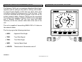
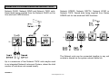
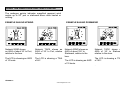
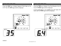
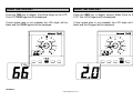
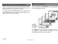
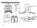
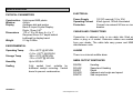
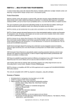
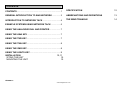
CONTENTS
CONTENTS..............................................................................1
SPECIFICATION
12
GENERAL INTRODUCTION TO B&G NETWORK ...............3
ABBREVIATIONS AND DEFINITIONS
13
INTRODUCTION TO NETWORK TACK ................................4
THE WIND TRIANGLE
14
EXAMPLE SYSTEMS USING NETWORK TACK..................5
USING THE ANALOGUE DIAL AND POINTER....................7
USING THE AWA KEY ...........................................................7
USING THE TWS KEY ............................................................7
USING THE TWA KEY............................................................8
USING THE VMG KEY............................................................8
USING THE LIGHTS KEY.......................................................9
INSTALLATION
10,11
SITING THE UNIT
10
MOUNTING THE UNIT
10
1
HB-0522-01
www.bandgservice.co.uk
GENERAL INTRODUCTION TO B&G NETWORK
The B&G Network range of instruments is designed to be
used as individual units or connected together to form an
integrated navigational system. A single network cable is
used to carry data and power between units. The latest
technology and screened cables throughout the Network
System ensure the ultimate protection from interference
between units and other systems. All Network instruments
can be linked to Network PILOT, Network CHART, Network
GPS or Network LORAN receivers or via NMEA 0183 (v1.5)
to other navigational equipment.
INSTRUMENTS
NAVIGATIONAL AIDS
Network SPEED
Network DEPTH
Network QUAD
Network WIND
Network TACK
Network DATA
Network GPS
Network LORAN
Network NAV
Network CHART
AUTOPILOTS
COMMUNICATIONS
Network PILOT
Network VHF
2
HB-0522-01
www.bandgservice.co.uk
INTRODUCTION TO NETWORK TACK
NETWORK TACK DISPLAY UNIT
The Network TACK unit is a analogue Magnified Wind Angle
repeater used for sailing on the wind or running, with a backlit Liquid Crystal Display (LCD) that can show other wind
information selected by pressing one of the five keys. It has
no sensor interfaces as all data is passed to the unit via the
system network cables. Network TACK must be connected
to a system that contains a Network WIND unit for wind data
and a Network SPEED unit (for true wind and VMG
functions) via the two network cable tails at the rear of the
unit.
The unit is capable of transmitting NMEA 0183 v1.5 data via
the network cables.
The five keys give the following selections:
• AWA
Apparent Wind Angle
• TWS
True Wind Speed
• TWA
True Wind Angle
• VMG
Velocity Made Good
• LIGHTS
Three levels of illumination and off.
3
HB-0522-01
www.bandgservice.co.uk
EXAMPLES SYSTEMS USING NETWORK TACK
Network QUAD, Network WIND and Network TACK units.
Speed data being supplied from the Network QUAD unit for
true wind and VMG functions.
Network SPEED, Network DEPTH, Network WIND and
Network TACK. Speed data being supplied from Network
SPEED unit for true wind and VMG functions.
The Network units can be connected together in any order
as data is shared via the system network cable link.
Up to a maximum of four Network TACK units maybe used
in an integrated Network Instrument System, where the total
number of units does not exceed twenty.
4
HB-0522-01
www.bandgservice.co.uk
USING THE ANALOGUE DIAL AND POINTER
The analogue pointer indicates magnified apparent wind
angles up to 500 port or starboard when close hauled or
running.
EXAMPLE SAILING DOWNWIND
EXAMPLE SAILING UPWIND
Network WIND shows
an AWA of about 30° to Port,
relative to the bow.
Network TACK shows an
AWA of 35° to Port, relative
to bow.
The LCD is showing an AWS
of 10 knots.
The LCD is showing a TWA
of 66°.
Network WIND shows an
AWA of about 150° to
Starboard, relative to the
bow.
The LCD is showing an AWS
of 10 knots.
Network TACK shows an
AWA of 35° to Starboard
relative to the stern.
The LCD is showing a TWA
of 160°.
.
5
HB-0522-01
www.bandgservice.co.uk
USING THE AWA KEY
USING THE TWS KEY
Press the AWA key to display Apparent Wind Angle on the
LCD. The LCD APP legend will be displayed.
Press the TWS key to display True Wind Speed on the LCD.
The LCD TRUE legend will be displayed.
If boat speed data is not available the LCD digits will be
blank and the TRUE legend will be displayed.
6
HB-0522-01
www.bandgservice.co.uk
USING THE TWA KEY
USING THE VMG KEY
Press the TWA key to display True Wind Angle on the LCD.
The LCD TRUE legend will be displayed.
Press the VMG key to display Velocity Made Good on the
LCD. The LCD V legend will be displayed.
If boat speed data is not available the LCD digits will be
blank and the TRUE legend will be displayed.
If boat speed data is not available the LCD digits will be
blank and the V legend will be displayed.
7
HB-0522-01
www.bandgservice.co.uk
USING THE LIGHTS KEY
USING VMG FOR BETTER PERFORMANCE
VMG is an indication of how efficiently the yacht is sailing
upwind or downwind. Maximising your VMG ensures you are
following the fastest route upwind or downwind.
The Network TACK Display unit has 3 levels of illumination
and off, controlled by the LIGHTS key. The level selected is
for the whole Network system.
As a basic rule when heading directly for a mark the boat
speed should be maximised, when tacking or gybing to the
mark the VMG should be maximised.
• L0
• L3
• L2
• L1
OFF
High
Medium
Low
The LIGHTS key also changes the illumination level of the
key legends, it always remains illuminated so even in
complete darkness the key can be located.
8
HB-0522-01
www.bandgservice.co.uk
INSTALLATION
MOUNTING
The display heads are supplied with a clip-in mounting
bracket which allows for easy installation, access from
behind is not necessary to secure the unit in place. However
to prevent theft and permanently fix the unit in position,
locking studs and thumb nuts are supplied.
Use the cutting template supplied to mark the centres of the
holes for the self-tapping screw, the fixing stud holes and the
mounting bracket.
SITING
All Network Instruments are designed for mounting on or
below deck. A mounting position should be selected where
they are:
•
•
•
•
Easy to read by the helmsman
On a smooth and flat surface
At least 100mm (4") from a compass
Accessible from behind for fitting locking studs if
required.
• The template allows 4mm (5/32") between adjacent units
for the suncover, increase this distance if required to
maximum of 60mm (2 3/8") between units or 180mm (3 1/8")
between centres. For greater distances between units
extension cables are available.
• Use a 70mm (2 3/4") diameter hole-cutter for the mounting
bracket hole.
• Use a 2.9mm for the self-tapping screw holes.
• Use a 5mm (3/32") drill for the locking stud holes.
• Secure the mounting bracket to the bulkhead with the
self-tapping screws supplied
• Fit the rubber sealing gasket around the mounting bracket.
• Screw the locking studs into the back of the display head (if
required).
• Carefully pass the cable tails through the mounting bracket
hole, connect the cables to the main units.
• Clip the display head into the mounting bracket.
• Secure the instrument with the thumb nuts supplied.
9
HB-0522-01
www.bandgservice.co.uk
INSTALLATION
10
HB-0522-01
www.bandgservice.co.uk
SPECIFICATION
PHYSICAL PARAMETERS
ELECTRICAL
Construction
Window
Display
Power Supply
Operating Current
Protection
Dimensions
Weight
High impact ABS plastic
Acrylic
Analogue dial and pointer
Back-lit Liquid Crystal Display:
Digits: 12mm 0.47"
110 x 110 x 25.4mm 4 x 4 x 1"
Requires 65mm 2.6" depth behind
bulkhead for display barrel
0.3 kg 0.66lbs
CABLES AND CONNECTIONS
Connection to adjacent units is via cable tails fitted with
either a plug or a socket. Extension cables are available
from your dealer. The cable tails carry power and NMEA
data between units.
ENVIRONMENTAL
Operating Temp
Storage Temp
Humidity
Sealing
12V DC nominal (10 to 16V)
40mA typical, 100mA illuminated
Connect via external 5A fuse or circuit
breaker.
-10 to +550C @ 93%RH
+14 to +1310F @ 93%RH
-25 to +700C @ 95%RH
-13 to +1580F @ 93%RH
Up to 95%RH
ALARM
Fully sealed front, suitable for
bulkhead cockpit mounting. Vented
barrel to prevent condensation.
$IIHDM
$IIVHW
$IIDBT
$IIVWR
$IIMTW
There is no internal audible alarm
NMEA OUTPUT SENTENCES
Heading
Speed and Heading
Depth
Apparent wind angle and speed
Sea temperature
11
HB-0522-01
www.bandgservice.co.uk
ABBREVIATIONS AND DEFINITIONS
THE WIND TRIANGLE
AWA
Apparent Wind Angle - The angle between the
boat's bow and the wind blowing across the
deck (at mast height).
AWS
Apparent Wind Speed - The wind speed across
the deck (at mast height).
TWA
True Wind Angle - The wind angle between the
boat's heading and the true wind (at mast
height). This is calculated from AWA, AWS and
boat speed. This is the wind relative to the
water, not the land.
TWS
True Wind Speed - The wind speed over the
water, independent of the boat's motion through
it. Calculated from AWA, AWS and boat speed.
VMG
Velocity Made Good - A measure of performance
upwind or downwind calculated from TWA and
boat speed.
12
HB-0522-01
www.bandgservice.co.uk