Transcript
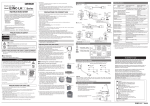
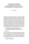
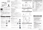
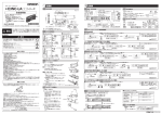
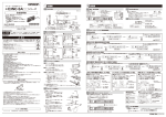
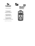
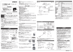
ST indicator
13.5
10.5
3
4
21.5
INSTRUCTION SHEET
© OMRON Corporation 2012 All Rights Reserved.
PRECAUTIONS ON SAFETY
●Keys to Warning Symbols
Indicates a potentially hazardous situation which, if not avoided, will
result in minor or moderate injury,or may result in serious injury or
death. Additionally there may be significant property damage.
●Explanation of signs
●Laser beam
Cautions to indicate potential Laser beam hazard
●Resolution prohibition
Indicates prohibition when there is a risk of minor injury from electrical
shock or other source if the product is disassembled.
28.8
Measurable area
E3NC-SH100
L = 35 to 100 mm
A = 15.92∼5.67°
3.3
32.8
41
11
25.4
27
11.6 9.9
6.5
7
8.35
19
3- Ø 3.2
18
16.4
Emitter center
Mounting brackets are E39-L185, L187 and L188.
Vinyl insulated cable
4-dia. 6-wire (cross section of conductor: 0.08 mm 2/
insulator diameter: dia 0.38 mm)
Standard length: 2 m Minimum bending radius: 12 mm
2.Sensor Head Display
[ST Indicator: Blue]
Turns ON when Smart Tuning is performed.
[OUT Indicator: Orange]
Turns ON when Output is ON.
ST button
Press both the ST button and
[S.TUNE] button at the same time to
execut tuning.
[STABILITY Indicator: Green]
Turns ON when output is ON steadily.
Fix the Reflective type sensor head with screws (M3). (tightening torque: M3, 0.3 N ・m)
Mounting dimensional drawing
(Unit: mm)
27±0.05
Checking the package contents
■ Shortening the connection cable for use
Do not disassemble the product. Doing so may cause the laser beam to
leak,resulting in the danger of visual impairment.
The E3NC-SH has the WARNING label
regarding laser on the side of the Sensor Head as
shown on the right igure.
Description label
Authentication label
When using devices in which E3NC-SH is installed
in the U.S., the devices are subjected to the U.S.
FDA (Food and Drug Administration) laser
regulations. E3NC-SH series is classified into Class1
by the standard of IEC/EN60825-1 according to
deviations of Laser Notice NO.50 of this standard,
and is scheduled to report to CDRH (Center for
Devices and Radiological Health).
Using in Europe
The E3NC-SH is categorized as a Class 1 device as stipulated in EN60825-1.
PRECAUTIONS FOR SAFE USE
Please observe the following precautions for safe use of the products.
(1)Installation Environment
・Do not use the product in environments where it can be exposed to inlammable/explosive gas.
・To secure the safety of operation and maintenance, do not install the product close to
high-voltage devices and power devices.
(2)Power Supply and Wiring
・Be sure to use a dedicated ampliier unit (E3NC-SA□□/E3NC-SA0). Connecting the sensor
to other ampliier unit may cause damage or ire.
・When short circuiting the cable, be sure to connect wires correctly according to the
speciication. Improper connection may cause damage or ire.
・High-Voltage lines and power lines must be wired separately from this product. Wiring them
together or placing them in the same duct may cause induction, resulting in malfunction or
damage.
・Always turn off the power of the unit before connecting or disconnecting cables.
OUT indicator (Orange), STABILITY indicator (Green),
ST indicator (Blue)
Ambient illumination
Illuminance on receiving optical side
Illuminance on receiving optical
side 4,000 lx max. (incandescent light) 2,000 lx max. (incandescent light)
Sunlight: 4,000lx max.
Sunlight: 8,000lx max.
Ambient temperature
Operating: -10 to 55°C, storage: -25 to 70°C
(with no icing or condensation)
Ambient humidity
Insulation resistance
Dielectric strength
Vibration resistance
Shock resistance
Degree of protection
Connection method
Material Case
Lens
Cable
Weight (packed state/
main unit only)
Operating and storage: 35% to 85% (with no condensation)
20 MΩ min. (500 VDC)
1000 VAC 50/60 Hz 1min
10 to 55 Hz. 1.5-mm double amplitude
2 hours each in X, Y, and Z directions
500m/s2 3 times each in X, Y, and Z directions
IEC standard, IP65
Connector joint model (standard cable length: 2 m)
Polybutylene terephthalate
Methacrylate resin
PVC
Approx. 125 g/ approx. 75 g
Instructhin Sheet
*1. The E3NC-SH is classified into Class 1 by the standard of EN60825-1 according to deviations of Laser Notice No.50
of FDA standard, and will be reported to CDRH (Center for Devices and Radiological Health).
*2. Measured using Omron’s reference sensing object (white paper).
*3. Defined at the 1/e 2 (13.5%) of the central intensity at the measurement distance. Measurement may be influenced if
there is light leakage outside the defined region and the surroundings of the target object have a high reflectance in
comparison to the target object. Also, when detecting a workpiece that is smaller than the spot size, a correct value
may not be obtained.
・Sensor head ×1 ・Manual (this paper) ×1
CHECK!
Do not expose your eyes to the laser radiation either directly (i.e., after
reflection from a mirror or shiny surface). Loss of sight may possibly
occur in case of the exposure to laser high power density.
35 to 250 mm
35 to 180 mm: 9 mm
180 to 250 mm: 25 mm
Approx. 1 mm (distance at 250 mm)
Indicator
Accessories
3.Installing Sensor Heads
3
■ Shortening the connection cable for use
WARNING
35 to 100 mm
35 to 50 mm: 1.5 mm
50 to 100mm: 3 mm
Approx. 0.5 mm (distance at 100 mm)
White tube
3-M
●Alert Statements
・ E3NC-SH@@ Sensor Head: Class 1
Measurement range
E3NC-SH250
L = 35 to 250 mm
A = 15.92∼2.27°
16
SAFETY PRECAUTIONS FOR USING LASER EQUIPMENT
The E3NC-LH use a laser as the light source. Lasers are classiied based on EN standard (EN
60825-1)
Distance configuration model
E3NC-SH250
E3NC-SH100
Visible-light semiconductor laser (660nm) 100 µW max.
(JIS standard Class 1, IEC/EN Class1, FDA Class1)
Spot size *3
1.5
L
11.6 9.9
Please observe the following precautions to prevent failure to operate, malfunctions, or undesirable
effects on product performance.
(1)Do not install the product in locations subjected to the following conditions:
・Surrounding air temperature outside the rating
・Rapid temperature luctuations (causing condensation)
・Relative humidity outside the range of 35 to 85%
・Presence of corrosive or lammable gases
・Presence of dust, salt, or iron particles
・Direct vibration or shock
・Relection of intense light (such as other laser beams, electric arc-welding machines, or
ultra-violet light)
・Direct sunlight or near heaters
・Water, oil, or chemical fumes or spray, or mist atmospheres
・Strong magnetic or electric ield
(2)Warming Up
・The circuitry is not stable immediately after turning the power ON, and the values gradually
change until the Sensor Head is completely warmed up.
(3)Maintenance and inspection
・Always turn off the power of the unit before connecting or disconnecting cables.
・Do not use thinner, alcohol, benzene, acetone, or kerosene to clean the sensor.
・If considerable foreign matter or dust collects on the front of sensor, use a blower brush (for
camera lenses) to blow off the foreign matter. Avoid blowing it off with your breath. For a small
amount of foreign matter or dust, gently wipe with a soft cloth. Do not wipe hard. If the surface
is damaged, false detection may result.
(4)Sensing Object For Relective Type Sensor Head
・The product cannot accurately measure the following types of objects:Transparent objects,
objects with an extremely low relective sensor ratio, objects smaller than the spot diameter,
objects with a large curvature, excessively inclined objects,etc.
Detection method
Model
Light source (wavelength)*1
25.4±0.05
The following notice applies only to products that carry the CE mark:
Notice:
This is a class A product. In residential areas it may cause radio
interference, in which case the user may be required to take adequate
measures to reduce interference.
PRECAUTIONS FOR CORRECT USE
Receiver center
A°
TRACEABILITY INFORMATION:
Representative in EU:
Manufacturer:
Omron Europe B.V.
Omron Corporation,
Wegalaan 67-69
Shiokoji Horikawa, Shimogyo-ku,
2132 JD Hoofddorp,
Kyoto 600-8530 JAPAN
The Netherlands
Ayabe Factory
3-2 Narutani, Nakayama-cho,
Ayabe-shi, Kyoto 623-0105 JAPAN
7
8
4
Item
Standard measurement gap
*2
STATIVITY indicator
Thank you for selecting OMRON product. This sheet primarily describes
precautions required in installing and operating the product. Before operating
the product, read the sheet thoroughly to acquire sufficient knowledge of
the product. For your convenience, keep the sheet at your disposal.
Refer to the user’s manual for details.
WARNING
6
3
5.5
(3.5)
ST button
Unit: mm
OUT indicator
5.05
2
13
E3NC-SH□□Series
Model
5.Specifications
1.Dimensions
12.8
Smart Laser Head(CMOS)
(3)Installation
・Use screws for mounting and be sure to tighten screws with a speciied torque.
(tightening torque: M3, 0.5N・m)
(4)Other Rules
・Do not attempt to disassemble, deform by pressure, incinerate, repair, or modify this product.
・When disposing of the product, treat as industrial waste.
・If you notice an abnormal condition such as a strange odor, extreme heating of the unit, or
smoke, immediately stop using the product, turn off the power, and consult your dealer.
Operation lever (White)
Push the operation lever at the operation slot with the slotted
screwdriver and pull out the wire to adjust the cable length.
The tip of the screwdriver must be 2 mm or less. The type of
screwdriver whose tip width becomes broaden toward its root
cannot be used.
16±0.05
When mounting a Sensor Head, take care not to touch the emitter and receiver.
Adhesion of finger marks may hinder correct measurements. If you have touched them,
wipe them with a clean soft cloth.
・Secure the connector to avoid vibration or shocks.
Caution on Mounting Direction
<Detection Near the Wall Surface>
<Cavity Detection>
(White)
(3) Push the slotted screwdriver all the way to the releasing slot
and pry the slotted screwdriver up and down lightly. When you
feel a click on the slotted screwdriver, pry it to the reverse
direction of the wire insertion direction. The operation lever will
recover with a click sound.
(4) Check that the operation lever recovers and the wire coating
enters into the wire insertion slot. The shield wire cover must
not be shorted circuited. (The wires are connected when you
pull the wire and feel a resistance.)
THE PRODUCTS CONTAINED IN THIS SHEET ARE NOT SAFETY RATED.
THEY ARE NOT DESIGNED OR RATED FOR ENSURING SAFETY OF
PERSONS, AND SHOULD NOT BE RELIED UPON AS A SAFETY
COMPONENT OR PROTECTIVE DEVICE FOR SUCH PURPOSES.
Please refer to separate catalogs for OMRON's safety rated products.
OMRON shall not be responsible for conformity with any standards, codes, or
regulations that apply to the combination of the products in the customer's
application or use of the product.
■ Procedure to connect the connector
(1) According to "STRIP GAUGE" shown on the side of the
product, strip the coating of the shield for 20 mm or less, strip
7 to 8 mm
the coating of the core wire for 7 to 8 mm, and twist the wire
for several times.
Connecting part
Wire coating
(2) Inser t the wire all the way to the wire
inser tion slot. Make sure that the wire
coating is located inside the wire insertiong
slot and the tip of the conductor passes
through the connection part. Connect wires
as follows. Terminal No.1: Shield (Red,
White sides), No.2: White, No.3: Red, No.4:
Brown, No.5: Blue, No.6: Shield (Brown,
Blue side).
Operation lever
Suitability for Use
The Sensor is less
The Sensor is easily inluenced by
inluenced by ambient ambient lighting, which may cause
detection value variations. *
lighting.
Wire insertion port
<Detection of Workpiece with Level Difference>
Stable detection is possible
regardless of level difference.
Release port
Detection is not possible if
the emitter or receiver section
is blocked.
Level difference may cause
an abnormal detection value.
Take all necessary steps to determine the suitability of the product for the
systems, machines, and equipment with which it will be used.
Know and observe all prohibitions of use applicable to this product.
NEVER USE THE PRODUCTS FOR AN APPLICATION INVOLVING
SERIOUS RISK TO LIFE OR PROPERTY WITHOUT ENSURING THAT THE
SYSTEM AS A WHOLE HAS BEEN DESIGNED TO ADDRESS THE RISKS,
AND THAT THE OMRON PRODUCT IS PROPERLY RATED AND
INSTALLED FOR THE INTENDED USE WITHIN THE OVERALL
EQUIPMENT OR SYSTEM.
See also Product catalog for Warranty and Limitation of Liability.
* Before performing tuning, apply mat paint on the wall surface or turn ON the background suppression
function to avoid laser light relection.
EUROPE
OMRON EUROPE B.V. Sensor Business Unit
Carl-Benz Str.4, D-71154 Nufringen Germany
Phone:49-7032-811-0 Fax: 49-7032-811-199
NORTH AMERICA
OMRON ELECTRONICS LLC
One Commerce Drive Schaumburg,IL 60173-5302 U.S.A.
Phone:1-847-843-7900 Fax : 1-847-843-7787
ASIA-PACIFIC
OMRON ASIA PACIFIC PTE. LTD.
No. 438A Alexandra Road #05-05-08(Lobby 2),
Alexandra Technopark, Singapore 119967
Phone : 65-6835-3011 Fax :65-6835-2711
CHINA
OMRON(CHINA) CO., LTD.
Room 2211, Bank of China Tower,
200 Yin Cheng Zhong Road,
PuDong New Area, Shanghai, 200120, China
Phone : 86-21-5037-2222 Fax :86-21-5037-2200
4.Mounting the sensor head
1. Open the protection cover.
2. Insert the sensor head, with the lock lever on
its connector area facing upward, all the way
into the connector port.
To remove it, press and hold the lock lever
then pull the sensor head out.
1
2
Lock lever
The connector cover of E3NC-SH is white.
Connect the cable correctly.
Connector cover: White
OMRON Corporation
D
OCT. 2009
E3NC-SH□□Series