1
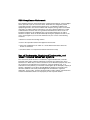
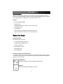
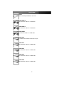
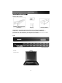
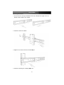
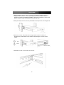
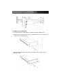
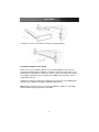
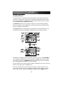
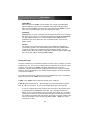
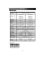
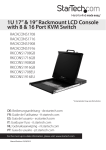
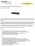
Rack Console with KVM Switch
17” LCD Rackmount Console with 8 Port KVM
19” LCD Rackmount Console with 16 Port KVM
RACKCONS1708
RACKCONS1916
Instruction Manual
Actual product may vary from photo
FCC Compliance Statement
This equipment has been tested and found to comply with the limits for a Class B digital
device, pursuant to part 15 of the FCC Rules. These limits are designed to provide
reasonable protection against harmful interference in a residential installation. This
equipment generates, uses and can radiate radio frequency energy and, if not installed
and used in accordance with the instructions, may cause harmful interference to radio
communications. However, there is no guarantee that interference will not occur in a
particular installation. If this equipment does cause harmful interference to radio or
television reception, which can be determined by turning the equipment off and on, the
user is encouraged to try to correct the interference by one or more of the following
measures:
• Reorient or relocate the receiving antenna.
• Increase the separation between the equipment and receiver.
• Connect the equipment into an outlet on a circuit different from that to which the
receiver is connected.
• Consult the dealer or an experienced radio/TV technician for help.
Use of Trademarks, Registered Trademarks, and
other Protected Names and Symbols
This manual may make reference to trademarks, registered trademarks, and other
protected names and/or symbols of third-party companies not related in any way to
StarTech.com. Where they occur these references are for illustrative purposes only and
do not represent an endorsement of a product or service by StarTech.com, or an
endorsement of the product(s) to which this manual applies by the third-party company in
question. Regardless of any direct acknowledgement elsewhere in the body of this
document, StarTech.com hereby acknowledges that all trademarks, registered
trademarks, service marks, and other protected names and/or symbols contained in this
manual and related documents are the property of their respective holders.
Instruction Manual
Table of Contents
Introduction . . . . . . . . . . . . . . . . . . . . . . . . . . . . . . . . . . . . . . . . . . . . . . . . . . . . .1
Features . . . . . . . . . . . . . . . . . . . . . . . . . . . . . . . . . . . . . . . . . . . . . . . .1
Before You Begin . . . . . . . . . . . . . . . . . . . . . . . . . . . . . . . . . . . . . . . . . . . . . . . . .1
Package Contents . . . . . . . . . . . . . . . . . . . . . . . . . . . . . . . . . . . . . . . .1
Accessory Products from StarTech.com . . . . . . . . . . . . . . . . . . . . . . .1
Installation and usage . . . . . . . . . . . . . . . . . . . . . . . . . . . . . . . . . . . . . . . . . . . .3
Hardware kit contents . . . . . . . . . . . . . . . . . . . . . . . . . . . . . . . . . . . . . .3
Mounting the Console . . . . . . . . . . . . . . . . . . . . . . . . . . . . . . . . . . . . .4
Connecting the Console/Module . . . . . . . . . . . . . . . . . . . . . . . . . . . . .6
Cascade Configuration . . . . . . . . . . . . . . . . . . . . . . . . . . . . . . . . . . . . .8
Turning on the console . . . . . . . . . . . . . . . . . . . . . . . . . . . . . . . . . . . . .8
Configuring display settings . . . . . . . . . . . . . . . . . . . . . . . . . . . . . . . . .8
Testing the console . . . . . . . . . . . . . . . . . . . . . . . . . . . . . . . . . . . . . . . .9
Panel controls and OSD functions . . . . . . . . . . . . . . . . . . . . . . . . . . . .9
Auto tune . . . . . . . . . . . . . . . . . . . . . . . . . . . . . . . . . . . . . . . . . . . . . .10
Input Source . . . . . . . . . . . . . . . . . . . . . . . . . . . . . . . . . . . . . . . . . . . .10
Brightness . . . . . . . . . . . . . . . . . . . . . . . . . . . . . . . . . . . . . . . . . . . . . .10
Contrast . . . . . . . . . . . . . . . . . . . . . . . . . . . . . . . . . . . . . . . . . . . . . . .10
Color . . . . . . . . . . . . . . . . . . . . . . . . . . . . . . . . . . . . . . . . . . . . . . . . . .11
Position . . . . . . . . . . . . . . . . . . . . . . . . . . . . . . . . . . . . . . . . . . . . . . . .11
Language . . . . . . . . . . . . . . . . . . . . . . . . . . . . . . . . . . . . . . . . . . . . . .12
Recall . . . . . . . . . . . . . . . . . . . . . . . . . . . . . . . . . . . . . . . . . . . . . . . . .12
Exit . . . . . . . . . . . . . . . . . . . . . . . . . . . . . . . . . . . . . . . . . . . . . . . . . . .12
Module Operation . . . . . . . . . . . . . . . . . . . . . . . . . . . . . . . . . . . . . . . . . . . . . . .13
Push Button Selection . . . . . . . . . . . . . . . . . . . . . . . . . . . . . . . . . . . .13
Hot-key commands . . . . . . . . . . . . . . . . . . . . . . . . . . . . . . . . . . . . . .16
Specifications . . . . . . . . . . . . . . . . . . . . . . . . . . . . . . . . . . . . . . . . . . . . . . . . . .19
Technical Support . . . . . . . . . . . . . . . . . . . . . . . . . . . . . . . . . . . . . . . . . . . . . . .20
Warranty Information . . . . . . . . . . . . . . . . . . . . . . . . . . . . . . . . . . . . . . . . . . . .20
i
Instruction Manual
Introduction
Thank you for purchasing a StarTech.com LCD Rack Console with KVM. This product
allows you to manage multiple computers using an integrated keyboard, mouse, and TFT
screen that slides into a compact 1U of rack space when not in use.
Features
• On Screen Display (OSD)
• Durable design
• Compatible with PC, Mac and Sun servers and systems
• Cascadable design
• Hot-pluggable
• Security features, including port locking and auto scan
• Login authentication restricts access to authorized users
Before You Begin
Package Contents
This package should contain:
• 1U LCD Rack Console Drawer (1)
• 1U Multi-Platform KVM Switch (1)
• Console Cable Kit (1)
• Mounting Rails - Set (1)
• Mounting Brackets
• Power Adapter (1)
Accessory Products from StarTech.com
To simplify connections between your new Rack Console/KVM Switch and the computers
you wish to control, contact your local StarTech.com dealer or visit www.startech.com for
cables or other accessories:
SVSERIALAD
Serial Mouse Adapter for SVxx31 StarView KVM Switches
USB2PS2
USB to PS2 Keyboard and Mouse Converter
1
Instruction Manual
SV125
Sun to PS/2 Keyboard/Mouse Converter
SVECONUS10
10 ft Ultra-Thin USB 2-in-1 KVM Cable
SVECONUS15
15 ft Ultra-Thin USB 2-in-1 KVM Cable
SVECONUS6
6 ft Ultra-Thin USB 2-in-1 KVM Cable
SVECON10
6 ft. IEEE-1394 FireWire Cable 6-pin to 6-pin
SVECON15
15 ft Ultra-Thin PS/2 3-in-1 KVM Cable
SVECON25
25 ft Ultra-Thin PS/2 3-in-1 KVM Cable
SVECON35
35 ft Ultra-Thin PS/2 3-in-1 KVM Cable
SVECON50
50 ft Ultra-Thin PS/2 3-in-1 KVM Cable
2
Instruction Manual
Installation and usage
Hardware kit contents
Screw kit
Side Rails with front and rear
brackets (2)
Keys (2)
Mounting Brackets
Please note: RACKCONS1708/RACKCONS1916 is comprised of two distinct
components - a Rackmountable Console and a Rackmountable KVM Module, as
illustrated below. The two devices are attached via a Centronics connector on the Rear
panel of the Console and similarly the front panel of the Module.
Module
Front Panel
Rear Panel
**16-port model shown
Console
Front view, open
3
Instruction Manual
Mounting the Console
1. Loosen the rear screws (pre-installed in side rails) and adjust the length of the rear
bracket to fit the depth of your cabinet:
2. Install the rail into the cabinet:
3. Tighten the screws that were loosened in Step 1:
4. Install the remaining rail, repeating Steps 1-3.
4
Instruction Manual
5. Slide the Module onto the Console side rails, connecting the Module and Console
using the male Centronics connector provided by the Console, and the female
Centronics connector provided by the Module. Ensure the connection is secure, and
that the module is firmly seated within the Console side rails.
6. Gently, but firmly insert the Console (with Module attached) into the left and right rails:
6. Unlock the console, and pull the left and right rail-lock switches towards you
simultaneously, and hold them in this position while pushing the console into the
cabinet:
Lock
Unlock
Rail Lock Switch
7. Install three screws on each side of the console:
5
Instruction Manual
8. Installation is now complete:
Connecting the Console/Module
To connect the KVM Console/Module to a computer, perform the following steps:
1. Remove the four screws from both sides of the KVM console. Be sure to retain these
screws for the next installation step.
2. Attach the mounting brackets to both sides of the KVM console, using the screws
removed in step 1.
6
Instruction Manual
3. From the rear of the cabinet, slide the KVM console onto the mounting rails.
4. Install one screw on each side of the console (as depicted below).
Connecting computers to the module
Attach each of your managed computers to your StarView KVM console’s PC ports
using ultra-thin KVM cables. The Module is capable of using either 2-in-1 USB or 3-in-1
PS/2 cables. Use the cables to connect one of the PC ports on the back of the switch to
the computer's keyboard, mouse, and video ports. Note: These instructions are for a
single KVM switch only.
Following this, plug the 12V DC power adapter into the power port on the KVM module,
and turn on the computers that will be controlled by the console.
Note: After the initial power up, you can hot-plug additional computers or slave KVM
switches without having to power down your KVM
7
Instruction Manual
Cascade Configuration
You can connect a second level of KVMs to one or more of your Master KVM console’s
PC ports. The KVM switches connected to the Master console are known as Slaves.
Once connected, the KVM switches will automatically configure themselves as either
Masters or Slaves. You can only connect an equal or “smaller” KVM to the Master KVM.
For example, a 16-port Master KVM switch can have both 16-port and 8-port slaves. An
8-port Master KVM switch can only have 8-port (or fewer) KVM slaves.
The 8-port KVM can support 64 PCs, with 8 x 8-port Slave KVMs, each connected to 8
PCs. The 16-port KVM can support 136 computers, with 8 16-port Slave KVMs, each
connected to 16 computers. The Slave KVM’s must be connected to the 1~8 ports, not
the A~H ports.
To cascade your KVMs, use a 3-in-1 PS/2 KVM cable to connect one of your Master
switch’s PC ports to the Slave switch’s console ports. When turning on your cascaded
switches, turn on the Master switch before turning on any of the others.
Turning on the console
Make sure all cables and the power cord are connected properly. Grasp the handle of
the drawer, pull the panel forward and up, then press the pushbutton in the top right hand
corner to enable the TFT screen.
The LED located to the left of the monitor panel should turn from orange to green,
verifying that the unit is operational.
Configuring display settings
After connecting the drawer and turning on your computer, you may need to configure
one or more of the following display settings to allow the computer to display at the
console’s native resolution. See Specifications for the correct resolution mode for your
model.
• Display mode (also called desktop area or video resolution)
• Refresh rate (also called vertical scan rate or vertical sync)
• Color depth (also called color palette or number of colors)
Each video card has several controls that allow you to adjust the display settings,
however, the software and driver for each video card is unique. In most cases, you can
adjust these settings using a program or utility provided by the manufacturer of the video
card. Most video cards use the Windows Display Properties control panel to configure
the display. To open the Windows Display Properties, click the right mouse button in a
blank area of the Windows desktop and then select Properties. The Settings tab usually
lets you change the Color Palette and the Desktop Area (X by Y pixel resolution).
Some video cards integrate additional features into the Windows Display Properties
control panel giving you extra setup options that are flexible and easy to use. For
8
Instruction Manual
example, the control panel may include an Advanced Properties button, an Adjustment
tab, or a Refresh tab for changing other settings. Other video cards have a separate
utility for setting display properties.
Whenever you change the resolution, color, or refresh rate, the image size, position, or
shape may change. This behavior is normal. You can readjust the image using the
monitor on-screen controls. For more information on the monitor on-screen controls, refer
to Panel controls and OSD functions. For more information on configuring the display
settings, please refer to the manual that accompanied your video card.
Testing the console
To test that the console is working properly, perform the following steps:
1. Power up the LCD Rack drawer, and then turn on your computer.
2. Make sure the video image is centered within the screen area. Use the OSD controls
to adjust the image (see Panel controls and OSD functions) or press the Auto
button on the right hand side of the monitor.
Note: You can adjust the horizontal and vertical position, contrast, and brightness to
better suit your video card and your personal preference.
Before you begin, make sure that power to all of the devices you will be connecting to the
console have been turned off. To prevent damage to your installation due to ground
potential difference, make sure that all of the devices being installed are properly
grounded. Once all peripherals have been connected, please power them on.
Panel controls and OSD functions
The following controls are located on the console monitor:
Controls
Descriptions
Soft power on/off. Adjacent LED is lit when on
Auto
Auto-synchronize and scale down display to any valid factory preset timings
Up
Press to scroll to the function you want to adjust.
Down
Press to scroll to the function you want to adjust.
Menu
To access the main menu. This button also acts as the Enter button.
9
Instruction Manual
Auto tune
Press the Auto tune button. The panel will adjust the display size automatically and also
tune the panel to its optimized state.
Input Source
1. Press the Menu button.
2. Use the Down and Up buttons to scroll.
3. Press the Menu button to enter, and you will see: VGA/DVI
4. Use the Down and Up buttons to select the input signal source.
5. Press the Menu button to save your selection.
Brightness
1. Press the Menu button.
2. Use the Down and Up buttons to scroll to
Brightness.
3. Press the Menu button to enter.
4. Use the Down and Up buttons to adjust the
brightness of the display.
Auto tune
Input Source
Brightness
Contrast
Color
Position
Language
Recall
Exit
5. Press the Menu button to save your selection.
Contrast
1. Press the Menu button.
2. Use the Down and Up buttons to scroll to Contrast.
3. Press the Menu button to enter.
2. Use the Down and Up buttons to adjust the contrast of
the display.
3. Press the Menu button to save your selection.
10
Auto tune
Input Source
Brightness
Contrast
Color
Position
Language
Recall
Exit
Instruction Manual
Color
1. Press the Menu button.
2. Use the Down and Up button to scroll.
3. Highlight Color, and press the Menu button to enter,
which will launch the following screen:
Icon
9300°K
7500°K
6500°K
User
Auto color
Return
To
To
To
To
To
To
Description
set CIE coordinates at 9300°K color
set CIE coordinates at 7500°K color
set CIE coordinates at 6500°K color
set user defined CIE
auto adjust color
exit and return to the previous page
Auto tune
Input Source
Brightness
Contrast
Color
Position
Language
Recall
Exit
4. Use the Down and Up buttons to adjust the contrast of
the display.
5. Press the Menu button to save your selection.
Position
1. Press the Menu button.
2. Use the Down and Up buttons to scroll.
3. Highlight Position and press the Menu button to enter,
which will launch the following screen:
Icon
Description
Image Pos To adjust the position of the image
OSD Pos To adjust the position of the OSD
Return
To exit and return to the previous page
4. Use the Down and Up buttons to scroll.
5. Press the Menu button to save your selection.
11
Auto tune
Input Source
Brightness
Contrast
Color
Position
Language
Recall
Exit
Instruction Manual
Language
1. Press the Menu button.
2. Use the Down and Up buttons to scroll.
3. Highlight Language, and press the Menu button to
select, which will launch the following screen:
English
German
French
Italian
Spanish
4. Use the Down and Up buttons to scroll, and highlight
the preferred language.
5. Press the Menu button to save your selection.
Recall
1. Press the Menu button.
2. Use the Down and Up buttons to scroll to Recall. Press the
Menu button to enter, where you will be able to select
Yes/No using the Down and Up buttons. Once you have
done so, press the Menu button. Note: selecting Yes will
return your settings to the factory default state. Select No if
you do not wish to make this change.
Exit
To exit the menu, scroll to Exit and press the Menu button.
12
Instruction Manual
Module operation
Push Button Selection
A computer may be selected by pressing the push buttons above the keyboard on the
Console, by issuing hot-key commands or by activating the OSD window. The indicator
LEDs change to reflect the computer port selected (red). The indicator flashes red when
it is in either Auto Scan or Manual Scan mode.
The K/M Reset function (on the module) reconfigures your system without powering
down your computers or your KVM switch. To reset the switch, press and hold the frontpanel 1 and 2 buttons simultaneously.
The Auto-Scan function automatically scrolls through your connected computers. Press
and hold the front-panel 7 and 8 buttons simultaneously to enter Auto Scan mode.
By hitting the left <CTRL> key twice within two seconds, you may see the Hotkey Menu
(if it is enabled as an OSD option). Or, by hitting the left <CTRL> key three times within
two seconds, you will see a KVM MENU screen (below) showing a list of the computers
with corresponding channel addresses, names and status.
The port number of the currently selected computer is displayed in red, same as the front
indicator, at the right corner of the OSD menu.
The color of a device name is green if it has power and is ready for operation, or the
color is white if it has no power. The OSD menu updates the color when it is activated.
Use the <> and <> arrow keys to highlight a computer and the <ENTER> key to
13
Instruction Manual
select it. Or, you may press <ESCAPE> to exit the OSD and remove the OSD menu
from the display; the status window returns to the display and indicates the currently
selected computer or operating status.
A triangle mark to the right of a name indicates the port is cascaded to a Slave; the
number at the left of the triangle mark shows the number of ports the Slave has, i.e. 8 for
an 8-port switch. The <ENTER> key brings you one level down and another screen pops
up listing the names of the computers on that Slave. The name of the Slave will be
shown at the upper right corner of the OSD menu. It is useful to group computers and
still be able to see the group name.
) to the right of a name indicates the computer is selected to be
An eye mark (
monitored in Scan mode. In OSD, this mark can be switched on or off by function key
<F2>. Press the <ESCAPE> key to exit OSD and to return to the selected computer; the
computer name is also shown on the screen.
Function key <F1> - To edit the name entry of a computer or a Slave, first use the
<> and <> arrow keys to highlight a port then press <F1> followed by name entry.
Valid characters are ‘A’~’Z’, ‘0’~’9’ and the dash (-) character. Lowercase letters are
converted to uppercase ones. Press <BACKSPACE> to delete one letter at a time.
Non-volatile memory stores all name entries until you change, even if the unit is powered
down.
) of a computer on or off.
Function key <F2> - Use this key to switch the eye mark (
First, use the <> and <> arrow keys to highlight it, then press <F2> to switch its eye
mark on or off. If Scan Type reads 'Ready PC + ', only the power-on and eye mark
selected computers will be displayed sequentially in Scan mode.
Function key <F3> - To lock a device (a computer or a Slave) from unauthorized access,
use Security. Security is effective for only one device (a computer or a Slave). To lock a
device, use the <> and <> arrow keys to highlight it, then press <F3>. Now, enter up
to 4 characters (‘A’~’Z’, ‘0’~‘9’, ‘-‘) followed by <ENTER> as new password. A Security)following its port number. To permanently
enabled device is marked with a lock (
disable the security function from a locked device, highlight it, press <F3> then enter the
password.
If you want to access the locked device temporarily, simply highlight it and press
<ENTER>. The OSD will prompt for the password. After entering the correct password,
you are allowed to use the device. This device is automatically re-locked once you switch
to another one. During Scan mode, OSD skips the security-enabled device. Note: Only
one device (a computer or a Slave) can be locked by this function at a time.
Please note: If you forget the password, the only way to
permanently disable the security function is to remove all possible
power sources from the Console. You will need to turn off all
computers and unplug all power adapters, then restart everything.
14
Instruction Manual
Function key <F4> - More functions are available by hitting <F4>. A new screen pops
up displaying more functions as described below. Most of them are marked with a
) indicating there are options to choose from. Using the <> and <> arrow
triangle (
keys, select the functions and press <ENTER>. Available options will be shown in the
middle of the screen. Again, using the <> and <> arrow keys to view options, then
press <ENTER> to select it. You can press <ESCAPE> to exit at any time.
Auto Scan
In this mode, the Console automatically switches from one powered computer to
the next, sequentially in a fixed interval. During Auto Scan mode, the OSD
displays the name of the selected computer. When Auto Scan detects any
keyboard or mouse activity, it suspends the scanning until activity stops; it then
resumes with the next computer in sequence. To abort Auto Scan mode, press the
left <CTRL> twice, or, press any front button. Scan Type and Scan Rate set the
scan pattern. Scan Type (<F4>:More\Scan Type) determines if scanned
computers must also be eye mark selected. Scan Rate (<F4>:More\Scan Rate)
sets the display interval when a computer is selected before selecting the next
one.
Manual Scan
Scan through power-on computers one by one by keyboard control. Scan Type
(<F4>:More\Scan Type) determines if scanned computers must also be eye mark
selected. Press the <> key to select the previous computer and the down arrow
key to select the next computer. Press any other key to abort Manual Scan mode.
Audio Stick
An optional multimedia module can be linked to the back of each KVM Module for
selecting microphone and stereo speaker signals. There are two options for Audio
Stick: On and Off. When set to On, audio selection follows computer selection.
When set to Off, audio selection stops following computer selection. It is useful if
you want to listen to a particular computer's audio signal while operating other
computers. The non-volatile memory stores the Audio Stick setting.
Scan Type
Ready PC + : In Scan mode, scan through power-on and eye mark selected
computers.
Ready PC: In Scan mode, scan through power-on computers. The non-volatile
memory stores the Scan Type setting.
Scan Rate
Sets the duration of a computer displayed in Auto Scan mode. The options are 3
seconds, 8 seconds, 15 seconds and 30 seconds. The non-volatile memory stores
the Scan Rate setting.
Keyboard Speed
The Console offers keyboard typematic settings that override similar settings in the
BIOS and in Windows. Available speed options are Low, Middle, Fast and Faster
as 10, 15, 20 and 30 characters/sec respectively. The non-volatile memory stores
15
Instruction Manual
the Keyboard Speed setting.
Hotkey Menu
When you hit the left <CTRL> key twice within two seconds, the Hotkey Menu
appears displaying a list of hot-key commands if the option is On. The Hotkey
Menu can be turned Off if you prefer not to see it when the left <CTRL> key is hit
twice. The non-volatile memory stores the Hotkey Menu setting.
CH Display
Auto Off: After you select a computer, the port number and name of the computer
will appear on the screen for 3 seconds then disappear automatically. Always On:
The port number and name of a selected computer and/or OSD status are
displayed on the screen all the time. The non-volatile memory stores the CH
Display setting.
Position
The position of the selected computer name and/or OSD status displayed on
screen during operation. The actual display position shifts due to different VGA
resolution, the higher the resolution the higher the display position. The nonvolatile memory stores the Position setting. UL as Upper Left, UR as Upper Right,
LL as Lower Left, LR as Lower Right. MI as Middle.
Hot-key commands
A Hot-key command is a short keyboard sequence used to select a computer, to activate
computer scan, etc. The Console constantly interprets keystrokes for hot-keys. A hot-key
sequence starts with two left <CTRL> keystrokes followed by one or two more
keystrokes. A built-in alarm generates a high-pitch beep for correct hot-key command;
otherwise, one low-pitch beep for error and the bad key sequence will not be forwarded
to the selected computer.
The short form hot-key menu can be turned on as an OSD function (<F4>: more\Hotkey
Menu) every time the left <CTRL> key is pressed twice.
L-CTRL: is the <CTRL> key located at the left side of the keyboard.
1~8/A~H: are the number keys '1' ~ '8' at the upper row of the keyboard and character
keys 'A' ~ 'H' case insensitive. Do not use the keypad at the right of the keyboard.
•
To select a computer by hot-key command, you must know its port number, which
is determined by the KVM Module connection. For a computer connected to a
Master, its port is represented by the PC port label (1~8 or A~H). For a computer
connected to a Slave, two characters represent its port. The first character is the
port number of the Master unit (1~8) and the second one is the port number of the
Slave (1~8 or A~H). Please note that only Master's 'PC 1' ~'PC 8' ports can be
connected to a Slave.
16
Instruction Manual
Left Ctrl + left Ctrl + 7
Selects a computer connected to port 7 of the Master.
Left Ctrl + left Ctrl + 6 + C
Selects a computer connected to port C of a Slave connected to port 6 of the
Master.
•
To start Auto Scan, automatically scan power-on computers one by one at a fixed
interval:
Left Ctrl + left Ctrl + F 1
When Auto Scan detects any keyboard or mouse activity, it suspends the scanning
till activity stops; it then resumes with the next computer in sequence. The length
of the Auto Scan interval (Scan Rate) is adjustable, see below. To abort the Auto
Scan mode, press the left Ctrl key twice.
Note: Scan Type determines whether an eye-marked computer is to be displayed
during Auto Scan.
Manual Scan enables you to manually switch back and forth between power-on
computers.
Left Ctrl + left Ctrl + F2
Press or to select the previous or the next computer in sequence. Press
any other key to abort the Manual Scan.
Note: Scan Type determines whether an eye-marked computer is to be displayed
during Auto Scan.
•
To adjust Scan Rate which sets the duration before switching to the next computer
in Auto Scan:
Left Ctrl + left Ctrl + F3
The 1UCABCONS sends one to four beeps indicating scan interval of 3, 8, 15 and
30 seconds respectively.
To adjust keyboard typematic rate (characters/sec), this setting over-rides that of
BIOS and any operating system:
Left Ctrl + left Ctrl + F4
The Console will generate 1 to 4 beeps corresponding to 10, 15, 20 and 30
characters/sec respectively.
17
Instruction Manual
Change Configuration while Running
A device (a computer or a KVM switch) at any 'PC x' port can be changed at any
time after initial power-up. If you change any one of the PC 1 to PC 8 ports
connection from a computer to a Slave or vice versa, or replace the devices of a
port, the OSD will update this change the next time it is activated.
Note: Any new device must be turned off before it is connected to the Master.
18
Instruction Manual
Specifications
RACKCONS1708
Certifications
RACKCONS1916
CSA, FCC, UL, CUL, CE, RoHS
Connectors
8 x VGA female input
1 x VGA female output
16 x VGA female input
1 x VGA female output
Inactive:
1 x PS/2 Keyboard 6-pin
Mini-Din (Female)
1 x PS/2 Mouse 6-pin
Mini-Din (Female)
Inactive:
1 x PS/2 Keyboard 6-pin
Mini-Din (Female)
1 x PS/2 Mouse 6-pin
Mini-Din (Female)
Power Adapter
Max Resolutions
Number of ports
Display Size
Panel Type
12V, 4A
Pixel Pitch
1280 X 1024 (XGA)
8
17”
Active Matrix TFT LCD
1280 X 1024 (SXGA)
16
19”
Active Matrix TFT LCD
Supports 0.264mm x 0.264mm
Supports 0.098mm x 0.294mm
Right-Left view 60~70 (Typ)
Up-Down View 45~60 (Typ)
Right-Left view 140 (Typ)
Up-Down View 140 (Typ)
Viewing Angle (CR>10)
Contrast Ratio
450:1
500:1
Brightness
White 250cd/m2 (Center 1 point Typ)
White 250cd/m2 (Center 1 point Typ)
Back Light
Supported Colors
Response Time
Four Lamps for Back Light
16.2M Colors (6-bit with FRC)
16.2M Colors (6-bit with FRC)
Rising Time 2ms, Decay Time 14ms
Rising Time 2ms, Decay Time 10ms
DOS, Windows (3.1, 9x, 2000, NT4, ME, XP, 2003 Server) Linux, Novell 3.12-6,
HP UX, SUN
Support PS/2, SUN and USB
VGA+2xPS/2 cable
VGA+2xPS/2 cable
106 key PS/2 keyboard with touch pad
45~80KHZ
45~80KHZ
100-240 VAC input
100-240 VAC input
25W, 19.05W for Panel
25W, 21.05W for Panel
10%~90%RH
10%~90%RH
Heavy duty steel materials
Operating System
Multi Platform
System Cables
Keyboard Mouse
Sync
Power Source
Power Consumption
Humidity
Chassis Construction
Keyboard Language
USA, UK, German, French, Spanish, Italian, Portuguese, Dutch, Swiss,
Belgium, Swedish, Norwegian, Danish, Japan, Taiwan, Russian
Dimensions
Part’s Weight
440x470x44mm
11.75kg
Power Indicator
Light Color
Status
GREEN
RED
RED
RED
ON
STANDBY
SUSPEND
OFF
19
490x470x44mm
12.75kg
Instruction Manual
Technical Support
StarTech.com’s lifetime technical support is an integral part of our commitment to provide
industry-leading solutions. If you ever need help with your product, visit
www.startech.com/support and access our comprehensive selection of online tools,
documentation, and downloads.
Warranty Information
This product is backed by a one-year warranty. In addition, StarTech.com warrants its
products against defects in materials and workmanship for the periods noted, following
the initial date of purchase. During this period, the products may be returned for repair, or
replacement with equivalent products at our discretion. The warranty covers parts and
labor costs only. StarTech.com does not warrant its products from defects or damages
arising from misuse, abuse, alteration, or normal wear and tear.
Limitation of Liability
In no event shall the liability of StarTech.com Ltd. and StarTech.com USA LLP (or their
officers, directors, employees or agents) for any damages (whether direct or indirect,
special, punitive, incidental, consequential, or otherwise), loss of profits, loss of business,
or any pecuniary loss, arising out of or related to the use of the product exceed the
actual price paid for the product. Some states do not allow the exclusion or limitation of
incidental or consequential damages. If such laws apply, the limitations or exclusions
contained in this statement may not apply to you.
20
About StarTech.com
StarTech.com is “The Professionals’ Source for Hard-to-Find Computer
Parts”. Since 1985, we have been providing IT professionals with the
quality products they need to complete their solutions. We offer an
unmatched selection of computer parts, cables, server management
solutions and A/V products and serve a worldwide market through our
locations in the United States, Canada, the United Kingdom and Taiwan.
Visit www.startech.com for complete information about all our products
and to access exclusive interactive tools such as the Parts Finder and the
KVM Reference Guide. StarTech.com makes it easy to complete almost
any IT solution. Find out for yourself why our products lead the industry in
performance, support, and value.
Revised: 12 April 2007 (Rev. A)