1
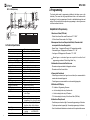
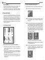
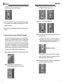
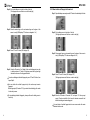
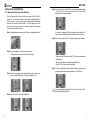
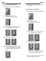
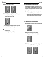
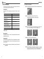
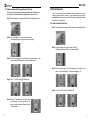
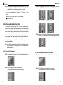
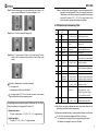
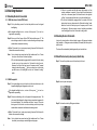
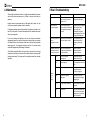
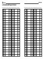
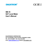
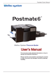
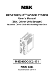
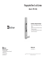
Fingerprint Door Lock System
(Model : BFS-1000)
Installation and Operation Manual
Thanks for choosing fingerprint doorlock from
BioEnter
Please read this manual carefully before starting
installation and operation
It is strongly recommended that you keep this
manual for future reference
BioEnter Ltd.
BioEnter International Inc.
Room #313, Unitechvill
1141-2, Backsuk-Dong, Ilsan-Ku, Koyang-Si
Kyunggi-Do, Korea
Tel : 82-31-907-5223
www.bioenter.co.kr
www.bioenter.co.kr
The design and specification of this product are subject to change without prior notice for product
development/improvement purposes.
BFS-1000
TABLE OF CONTENTS
1.
1.1
1.2
1.2.1
1.2.2
1.3
1.4
2.
2.1
2.1.1.
2.1.2
2.1.3
2.2
2.2.1
2.2.2
2.3
2.3.1
2.3.2
2.3.3
2.4
2.4.1
2.4.2
2.5
2.5.1
2.5.2
2.6
2.6.1
2.7
2.7.1
2.7.2
2.8
2.8.1
2.9
2.9.1
2.9.2
2.10
3.
3.1
3.1.1
3.1.2
3.2
3.3
4.
5.
5.1
5.2
6.
7.
8.
Introduction
Product Concepts
Package Contents
Standard Configuration
Option
Description of Components & Exploded View
Technical Specification
Programming
- Helpful Hints for Programming
Fingerprint Enrollment
How to enroll Master Finger
How to enroll Sub-Master Fingers
How to enroll User Fingers
Fingerprint Deletion
How to delete a single Fingerprint from lock
How to delete all Fingerprints from lock
User Access Code (PIN Code)
How to enroll User Access Code (PIN Code)
How to delete a single User Access Code (PIN Code)
How to delete all User Access Codes (PIN Codes)
Temporary Unlock Mode
How to set Temporary Unlock Mode
How to set Automatic Locking Mode
Temporarily Remove & Reinstate Fingerprint
Temporarily Remove a single Fingerprint from the lock
Reinstate a single removed fingerprint to the lock
Sound Setting Mode
How to set Sound Mode
Automatic “Fingerprint Sensor On” Mode
How to set automatic “Fingerprint Sensor On” Mode
How to set manual “Fingerprint Sensor On” Mode
Time Setting Mode
How to set Time
Master Finger Mode/User Finger Mode
How to set User Finger Mode
How to set Administration Mode
Programming Code Summary Table
Unlocking the door
Unlocking the door from outside
with User Access Code
with Fingerprint
Unlocking the door from inside
Unlock the door using emergency cylinder key
Audit Trail Data Kit (Option)
Installation of the lock
Checking before installation
Installation template
Maintenance
Basic Troubleshooting
ID Number and Fingerprint Record
Please read this manual carefully before operation. If any problem occurs or
if you need further instruction or assistance, please contact your BioEnter Dealer.
2
1. Introduction
3
3
4
4
4
5
6
7
8
9
10
12
13
13
15
16
16
18
19
20
20
21
23
23
24
26
27
28
29
30
31
31
32
32
33
35
36
36
36
36
37
37
38
39
39
39
40
41
42
1.1 Product Concepts
Designed for User convenience
No more keys, cards or remotes. The ultimate convenience of nothing to carry,
forget, pass on, be duplicated or to have stolen. Plus, very easy and quick to
enroll and to verify fingerprints.
Highest Security Level
Fingerprint-based identification is the oldest and the most reliable among all
the biometric technologies because your fingerprints are unique and invariable
throughout your lifetime.
Adapted the 4th Generation/World best Optical Sensor
The 4th generation optical sensor using world’s most reliable fingerprint
algorithm ranked number 1 position in International Fingerprint Verification
Competition (IFVC) with the lowest error rate in light category
Sufficient fingerprint capacity
1,000 fingerprints in 1:N mode can be enrolled
Auto Locking, Temporary open and Temporary Fingerprint Removal mode
User can set up auto locking, temporary open mode or temporary fingerprint
removal mode
Audible/visible indicators
LED light and buzzer sound indicate operation results
Voice prompt/Silence mode
Voice guidance is available to tell you the operation results
Emergency User Access Code and Terminals for External Power Source
User Access Code can be used in case your enrolled finger is injured, or to
allow others emergency access. A 9V square battery can be used externally to
provide power if the internal batteries are run down.
Master Finger (Administer) Mode
Master finger is necessary for fingerprint enrollment/deletion and change of
function set-up in “master finger mode” to enhance general security.
Emergency Override Mechanical Cylinder Key
Mechanical key used in case of an emergency
Sleep mode and initiation sensor
The lock powers down when not in use. In manual “Fingerprint Sensor On” mode,
the infrared initiation sensor will “wake up” the fingerprint sensor when a finger is
placed on the sensor glass, thus improving battery life and sensor efficiency.
3
BFS-1000
1.3 Description of Components & Exploded view
Connector for DC Power source
DC (6V) can be connected to and used as well where the battery does not
work properly due to cold weather.
Audit Trail (Option)
Entry log data such as time of entry and ID stored in the lock can be
downloaded up to 1,000 events to PC through serial cable
- Description of Components
Front Body
Back Body
Applications
stand-alone lock for commercial and residential
Keypad Cover
LED Display
1.2 Package Contents
Battery Cover
Keypad
1.2.1 Standard Configuration
Sensor
LED indicator
Green: Access granted
Red: Access denied
Emergency Key Cover
Fire-rated handle
Front Body
Back Body
Humidity gaskets
Handles
Inner body plate
- Exploded View
BFS-1000S(Single Latch)
Handle Pins
Emergency
Override Keys
bolts, screws and
hexagonal wrench
AA Batteries
ῤ
ῡ
User's manual
ῢ
ῤ
Ῥ
ΰ
Ύ
ῧ
1.2.2. Option
Audit Trail Kit
ῦ
Lockset Type
Ῠ
Ῡ
Ῡ
῭
Ὺ
CAUTION
4
Ὺ
Ῠ
῭
Please note that the cut point
should be always upper ditection
Single Latch
(Standard)
ῥ
Mortise
(Option)
No
1
2
3
4
5
6
7
8
Description
Outer Body
Inner Body
Battery Cover
Rubber Pad
Inner Body Plate
Handles
Single latch
handle Latch Pins
No
9
10
11
12
13
14
Description
Outer Body Fixed Screw
Inner Body Fixed Screws
Battery Cover Fixed Screw
Outer-Inner Body Fixed Screw
Handle Fixed Screw
Inner Body Fixed Screw
΅
ῦ
Specification
M5 x 20mm. 2ea
M4 piece screw. 2ea
M4. 1ea
M5 x 25mm. 1ea
M5 x 10mm. 2ea
M5 x 10mm. 1ea
Mortise Latch
(Option)
5
BFS-1000
BFS-1000M(Mortise)
ῤ
ῡ
ῢ
ῤ
Ῥ
2. Programming
ΰ
Ύ
ῧ
ῥ
Ὺ
Ῡ
῭
ῦ
Ῠ
Ῠ
Ῡ
῭
΅
ῦ
Ὺ
CAUTION
Please note that the cut point
should be always upper ditection
No
1
2
3
4
5
6
7
8
Description
Outer Body
Inner Body
Battery Cover
Rubber Pad
Inner Body Plate
Handles
Mortise
handle Latch Pins
No
9
10
11
12
13
14
Description
Outer Body Fixed Screw
Inner Body Fixed Screws
Battery Cover Fixed Screw
Outer-Inner Body Fixed Screw
Handle Fixed Screw
Inner Body Fixed Screw
Specification
M5 x 20mm. 2ea
M4 piece screw. 2ea
M4. 1ea
M5 x 25mm. 1ea
M5 x 10mm. 2ea
M5 x 10mm. 1ea
Thickness of the door
Material
Dimension
Weight (Net)
Operating Environment
Safety Certification
6
Helpful Hints for Programming
1.User Access Codes (PIN Code) :
- Default User Access Code under ID number at “01” : “0000”
- All User Access Codes consist of 4 to 12 digits
2. Management Levels and fingers identified by ID numbers that
correspond to the stored fingerprints :
1.4 Technical Specification
Item
Fingerprint sensor
Sensor resolution(sensing size)
Enrollment time
Verification time
False Rejection Rate (FRR)
False Acceptance Rate (FAR)
Fingerprint Scanning
User Capacity
Initiation sensor
Lock Type
Supply Voltage
Power
Battery life
LED Display
Emergency Power Source
Emergency Override Key
LED Display
Audible/Visual Guidance
Audit Trail
The function button used for programming is hidden by the battery cover on the
back body. This means that only people authorised to be on the inside and with
knowledge of the lock programming will be able to add/delete/change data and
settings. The door will need to be open when programming, in order to give access
to the front and back of the lock.
Technical parameters
The 4th Generation CMOS Optical Sensor
500 dpi (16 x 19mm)
< 1 second
< 1 second
1/30 ~ 1/100
1/100,000 ~ 1/1,000,000
twice to get on fingerprint template
up to 1,000 fingerprints (1: N Mode)
Infrared Sensor applied
UL Grade 1 latch(Standard), Mortise (Option)
DC 12V
1.5V AA x 8 Alkaline battery
Approx. 12 months (20 times/day)
ID Number, or program or error codes
Terminal for 9V square battery
Mechanical Cylinder Key
ID Number indicator
Voice/Silence, LED and Buzzer
Entry log data downloadable up to 1,000
events (Option)
38mm ~ 60mm
Body
: Zinc alloy die-casting
Keypad/Battery Cover : AL alloy fie-casting
Front Body : 80(w) x 290(h) x 39(d)mm
Back Body : 80(w) x 290(h) x 39(d)mm
5.5 Kg
- Temperature :
-20 ~ +70
- Humidity :
45% RH-80% RH
FCC, CE
- Master Finger : 1 fingerprint at ID number “00” assigned automatically
- Sub master fingers : 9 fingerprints at ID numbers “01” ~ “09”
- User fingers : 990 fingerprints at ID numbers “10” ~ “999”
Master finger or sub-master fingers are required to be verified for all
programming procedure in “Master Finger Mode” only
3.Information to be recorded for future use
-ID numbers and personal details of fingerprint enrollment
-ID numbers and User Access Codes
4. Fingerprints Enrollment
- Several finger enrolment (one finger from each hand) are recommended for
master and sub-master fingerprints
- Pointer fingers are recommended to use when enrolling fingerprints
5. Definition of LED Display
- F0 : Initiation of Programming Processes
- no : Lock is waiting for the entry of function code
- i d : Lock is waiting for the entry of ID number
- P0 : Lock is waiting for the entry of User Access Code (PIN Code)
6. Indication of Beep Sounds
- Double beep sound and a red light : Unsuccessful programming or Verification
- Triple beep sound and a green light : Successful programming or Verification
- Alarm Sound indicates the batteries are low and need to be replaced with new ones
7
BFS-1000
7. Master Finger Mode
- This lock is pre-set in “Master Finger” mode and you are required to verify
Master finger or sub-master fingers first in all programming processes
- You can change to “User Finger” mode if you prefer simple programming
processes which do not require Master finger (or sub-master finger) verification
2.1.1 How to enroll master finger (ID number : 00)
This is the first fingerprint enrollment after successful installation of the lock on the door.
Step 1: Open battery cover and press the “F” button in the back body
2.1 Fingerprint enrollment
This lock is pre-set in the Master Finger (Administer) mode. This means that
Master Finger is required to verify for all the enrollment/deletion of the
fingerprints/User Access Codes (PIN Codes) and change of data/setting. You
can change the setting to User Finger mode where you do not need Master
Finger to verify for all the enrolment/deletion of the fingerprints/User Access
Codes (PIN Codes) and change of data/setting. (Please refer to 2.9 Master
Finger/ User Finger Mode)
Correct Fingerprint Placement
Step 2: Pull up the sliding cover in the front body of the lock within 10 seconds
upon the completion of Step 1. You should see the fingerprint sensor
light up in red
Step 3: As soon as the sensor light comes on (in red, as explained in the Step
2), place the finger of your choice - flat, firmly against the surface of the
sensor (scanning platform). When the sensor light turns off, remove
your finger and then promptly put it back on the scanning platform
again. The sensor will light up in red the second time and then turn
itself off following the second scan of that same finger. You will hear a
triple beep sound indicating the success of this fingerprint enrollment
and then see the LED display “id”
ID number “00” will be assigned automatically for master finger
Recommendation on Finger for enrollment and verification
1. Moist fingers give better images than dry fingers. If you have difficulty in
enrolling or verifying your fingerprint, try to moisten your finger with your
breath or a moisture
2. Dirty fingers are not recommended to apply not only generating obscure
fingerprint image,but also possible scratching the glass of the fingerprint
sensor. Make your finger clean before use
3. Pointer fingers are recommended to use when enrolling fingerprint. They are
the easiest and most convenient fingers to use in programming and
verification process.
8
Master fingerprint will remain undeleted until deletion of all fingerprints
or factory reset mode is made.
Step 4: If you want to register other finger continuously, then put your preferred
“ID” number (01 ~999) and press “#”. (or just press “#” for next
available ID number) and the fingerprint sensor will turn on for the new
fingerprint enrollment continuously.
9
BFS-1000
(if you do not complete Step 4 above within 5 seconds, the mode will be
changed to main control mode and LED displays “no”).
“no” in LED means the lock is waiting for entry of function codes (for example :
“01” for sub-master or user enrolment) for further programming. (refer to 2.10 for
programming code table)
Step 3: Place the master finger on the glass of the sensor to verify
(LED displays “F0” and soon changed to “no”)
Step 4: Press “01” and “#” button (LED displays “id”)
You can exit from programming mode by pulling down the sliding cover in the
front body.
2.1.2 How to enroll sub-master fingers (ID Number 01 through 09)
After successful master fingerprint enrolment, you can enroll sub-master
fingerprints up to 9 fingers with assigned ID number at 01 through 09. Each
sub-master fingerprint can also be used to verify for all the enrolment/deletion
of the fingerprints/User Access Codes (PIN Codes) and change of data/setting
exactly same as master fingerprint. For your own security and maximum
convenience, you are recommended to enrol several sub-master fingers from
each hand and from your family member to be prepared for difficulty in verifying
your master finger. (for example : the injury to the master finger etc).
Step 5: Enter ID number with 2 digits between 01 and 09 and press “#” button
or just press “#” button
The fingerprint sensor will then turn on with a red light and LED
displays ID number you just entered (in case of entering ID + “#”) or
next available(empty) ID number (in case of pressing “#” only)
Enter ID number (e.g. : “02”) and “#”
Step 1: Open battery cover and press the “F” button in the back body of the lock
Please record the ID number and the details for each fingerprint
enrolled. The correct ID number will be needed when deleting an
individual fingerprint (Refer to 2.2.1 for deletions)
Step 6: Place chosen sub-master finger on the glass of the fingerprint sensor
twice while the fingerprint sensor turns on and off.
Step 2: Pull up the sliding cover in front body of the lock
(The fingerprint sensor will then turn on with a red light)
10
11
BFS-1000
A triple beep sound and a green light indicate the success of the sub-master
finger enrollment and LED displays “id” for more sub-master finger enrollment.
To continue enrolling more sub-master fingers, or try again if unsuccessful,
enter “ID” number (“01” through “09”) and press “#” button and then repeat
Step 6
To stop enrolling sub-master finger, please pull down the sliding cover in
the front body
2.1.3 How to enroll user fingers (ID Number 10 through 999)
The ID numbers assigned for user fingerprints are from “10” through “999” and
you can take same steps for sub-master fingerprints with different ID numbers.
Step 4: Press “01” and “#” button (LED displays “id”)
Step 5: Enter an ID number, which is a 2 - or 3 - digits number’s between “10”
and “999” and press “#” button
(The fingerprint sensor will then turn on with a red light and LED
displays ID number you just entered)
Please record the ID number and the details for each fingerprint enrolled.
please note that you need this id number when you delete the fingerprint
that’s associated with this number (Refer to 2.2.1 for deletions)
Step 6: Place chosen user finger on the glass of the fingerprint sensor twice
while the fingerprint sensor turns on and off twice.
Step 1: Open battery cover and press the “F” button in the back body of the lock
A triple beep sound and a green light indicate the success of the user finger
enrollment and LED displays “id” for more user finger enrollment.
Step 2: Pull up the sliding cover in the front body of the lock
(The fingerprint sensor will then turn on with a red light)
To continue enrolling more user fingers, or try again if unsuccessful, enter
“ID” number (“10” through “999”) and press “#” button and then repeat Step 6
To stop enrolling user finger, please pull down the sliding cover in front body
CAUTION : When you press “#” button without entering your own ID
number to enroll more user fingers, the next available ID Number will be
automatically assigned and might be enrolled as sub-master fingers if the
assigned ID numbers are between “01” through “09”
Step 3: Place master finger or sub-master finger on the glass of the sensor to
verify (LED displays “F” and soon changed to “no”)
2.2 Fingerprint Deletion
2.2.1 How to delete Single Fingerprint from lock
Step 1: Open the battery cover and press the “F” button in the back body of the lock
12
13
BFS-1000
Step 2: Pull up the sliding cover in the front body of the lock
(The fingerprint sensor will then turn on with a red light)
Step 3: Place the master finger or the sub-master finger on the glass of the
sensor to verify (LED displays “F0” and soon changed to “no”)
2.2.2 How to delete all Fingerprints from Lock
Step 1: Open the battery cover and press the “F” button in the back body of the lock
Step 2: Pull up sliding cover in front body of the lock
(The fingerprint sensor will then turn on with a red light )
Step 4: Press “02” and “#” button (LED displays “id”)
Step 3: Place master finger or sub-master finger on the glass of the sensor to
verify (LED displays “FO” and soon changed to “no”)
Step 5: Enter the ID number (2 or 3 digits) of the enrolled fingerprint you wish
to delete and press “#” button. A triple beep sound and a green light
indicate the success of the fingerprint deletion
To continue deleting an individual fingerprint, press “02” and “#” button, then
repeat Step 5.
Step 4: Press “03” and “#” button (LED displays “PO”)
(The fingerprint sensor will then turn on with a red light)
You can delete all enrolled fingerprints by this mode except master
fingerprint.
Master fingerprint (ID number “00”) is protected from deleting by this mode
for the safety reason.
To stop deleting individual fingerprint, please pull down the sliding cover in
front body
Step 5: Enter the PIN code at ID number “01” and press “#”. Voice prompt
saying “Function installed” will be heard to indicate successful total
deletion including sub-master fingerprint
You can delete all enrolled fingerprints but user access codes will remain
undeleted in this mode.
14
15
BFS-1000
2.3 User Access Code (PIN Code)
2.3.1 How to enroll User Access Code (PIN Code)
Step 5: Enter the ID number of the PIN Code (Unoccupied ID number between
“01” and “05”) you wish to enrol and then press “#” button (LED
displays ID number you just entered)
Each lock comes with the factory default User Access Code of 0000 at ID
number “01”. You can enroll User Access Codes up to 5 including default User
Access Code. For your own security, you are recommended to immediately
delete default User Access Code (0000 at “01”) and register a new User
Access Codes of your own choice (4 to12 digits), and also to consider doing
them at various intervals in the future.
Step 1: Open the battery cover and press the “F” button in the back body of the lock
If you want to change the PIN code already enrolled, delete the ID
number of the enrolled PIN Code first and then enrol new PIN Code
Step 6: Enter in your own PIN Code (4 to 12 digits) and then press # button
Step 2: Pull up the sliding cover in the front body of the lock
(The fingerprint sensor will then turn on with a red light)
Please record the ID number and the PIN Code for each enrolment
and the change.
This information will be needed when deleting PIN Code
(Refer to 2.3.2 for User Access Code deletion)
Step 7: Do Step 6 again (double entry is required). A triple beep sound and a
green light indicate the successful enrollment of your PIN Code.
Step 3: Place the master finger or the sub-master finger on the glass of the
sensor to verify (LED displays “F0” and soon changed to “no”)
To continue enrolling and changing PIN Code, press “04” and “#” button
and then repeat Step 5 through Step 7.
Step 4: Press “04” and “#” button (LED displays “id”)
16
17
BFS-1000
2.3.2 How to delete a single User Access Code (PIN Code)
Step 1: Open the battery cover and press the “F” button in the back body of the lock
To continue deleting a User Access Code, press “05” and “#” button and
then repeat Step 5
2.3.3 How to delete all User Access Codes (PIN Codes)
Step 1: Open the battery cover and press the “F” button in the back body of the lock
Step 2: Pull up the sliding cover in the front body of the lock
(The fingerprint sensor will then turn on with a red light)
Step 2: Pull up the sliding cover in the front body
(The fingerprint sensor will then turn on with a red light)
Step 3: Place the master finger or the sub-master finger on the glass of the
sensor to verify (LED displays “F0” and soon changed to “no”)
Step 3: Place the master finger or the sub-master finger on the glass of the
sensor to verify (LED displays “F0” and soon changed to “no”)
Step 4: Press “05” and “#” button (LED displays “id”)
Step 4: Press “06” and “#” button (LED displays “id”)
Step 5: Enter the ID number of the User Access Code you wish to delete and
then press “#” button (LED displays ID number you just entered) A
triple beep sound and a green light indicate the successful deletion of
the PIN Code.
A triple beep sound and a green light indicate the successful deletion
of all PIN Codes except factory default PIN code (“0000”) at “01”.
Factory default User Access Code (“0000”) at ID number “01” will be
reinstated after the completion of all PIN codes deletion.
18
19
BFS-1000
2.4 Temporary Unlock Mode
This lock is pre-set in “Automatic Locking Mode”. After being electronically
opened, it will automatically lock within 5 seconds of the door remaining in, or
returning to, its fully closed position.
However, you can set a “Temporary Unlock Mode” to enable free access
without the use of fingerprints or User Access Code. For example, this is useful
for storeroom and office doors that need to remainunlocked during office hours.
2.4.1 How to set the temporary unlock mode
Step 1: Open the battery cover and press the “F” button in the back body of the lock
Step 5: Enter “0” and then press “#” button. Voice prompt saying “Manual
closing mode” will be heard to indicate success of Temporary Unlock
Mode setting.
In this mode, automatic locking within 5 seconds after the door is opened
and the closed (Automatic Locking Mode) is not applied, and the lock will be
kept unlocked.
In order to lock the door during this mode (temporary unlock mode) is still
on, just press “#” button or open and then close the sensor cover of the front
body. The “temporary unlock mode” will be resumed with verification by any
enrolled fingers.
Step 2: Pull up the sliding cover in the front body of the lock
(The fingerprint sensor will then turn on with a red light)
Step 3: Place the master finger or the sub-master finger on the glass of the
sensor to verify (LED displays “F0” and soon changed to “no”)
Step 4: Press “07” and “#” button (LED displays “id”)
20
2.4.2 How to set automatic Locking mode
Step 1: Open the battery cover and press the “F” button in the back body of the lock
Step 2: Pull up the sliding cover in the front body of the lock
(The fingerprint sensor will then turn on with a red light)
Step 3: Place the master finger or the sub-master finger on the glass of the
sensor to verify (LED displays “F0” and soon changed to “no”)
21
BFS-1000
Step 4: Press “07” and “#” button (LED displays “id”)
2.5 Temporarily Remove & Reinstate Fingerprints
An enrolled fingerprint can be temporarily removed without being deleted. It
can then be reinstated, as needed, without having to be re-enrolled. This
allows certain enrolled people to be granted or denied access for temporary
periods on a regular or irregular basis.
Step 5: Enter the ID number in one digit (“1”) and then press “#” button. Voice
prompt saying “Automatic closing mode” will be heard to indicate
success of Automatic Locking mode setting.
Note: - The total number of fingerprints that can be temporarily removed from
the lock is limited to 20 at any point in time.
- Take care to note all temporary removals and reinstatements in the ID
Number and Fingerprint Record on page 39 and 40 of this manual.
2.5.1 Temporarily remove a single fingerprint from lock
Step 1: Open the battery cover and press the “F” button in the back body of the lock
In this mode, this lock will be automatically locked within 5 seconds of the
door returning to its fully close position after having been opened
ID number for Temporary Unlock/Automatic Locking Mode
0 : Temporary Unlock Mode
1 : Automatic Locking Mode (Factory default Mode)
Step 2: Pull up the sliding cover in the front body of the lock
(The fingerprint sensor will then turn on with a red light)
Step 3: Place the master finger or the sub-master finger on the glass of the
sensor to verify (LED displays “F0” and soon changed to “no”)
22
23
BFS-1000
Step 4: Press “08” and “#” button (LED displays “id”)
Step 5: Enter the ID number in two or three digits of the enrolled fingerprint you
wish to temporarily remove, and then press “#”. A triple beep sound
indicate a successful temporary removal.
To continue the Temporary Removal of other individual fingerprints, up to
the maximum limit of 20 at any point in time, just press “8” and “#”, and then
repeat Step 5.
Master and sub-master fingers at ID number “00” ~ “09” can not entered in
Step 5 and therefore can not be temporarily removed
Step 3: Place the master finger or the sub-master finger on the glass of the
sensor to verify (LED displays “F0” and soon changed to “no”)
Step 4: Press “09” and “#” button (LED displays “id”)
Step 5: Enter the ID number in two or three digits of the enrolled temporarily
removed fingerprint you wish to reinstate, and then press “#”. A triple
beep sound indicate a successful reinstatement.
To continue reinstating other temporarily removed individual fingerprint,
press “9” and “#”, and then repeat Step 5.
2.5.2 Reinstate a single removed fingerprint to the lock
Step 1: Open the battery cover and press the “F” button in the back body of the lock
Step 2: Pull up the sliding cover in the front body of the lock
(The fingerprint sensor will then turn on with a red light)
24
25
BFS-1000
2.6 Sound Setting Mode
2.6.1 How to set sound mode
This lock pre-set in the “Voice On” mode. There are 3 modes to choose from
as per your preference and environment situation.
Step 1: Open the battery cover and press the “F” button in the back body of the lock
Voice Mode (1)
In this mode, results of programming or operation will be heard in voice as
follows.
Function
Lock is open after finger verification
Lock is closed
When programming code for PIN code
enrollment is ready
When programming code for fingerprint
enrollment is ready
After the programming has been
completed successfully
After programming of automatic locking
mode has been completed
After programming of Temporary
Unlock mode has been completed
When batteries are low or run out
Voice Guidance
Is opened
Is closed
Password register
Step 2: Pull up the sliding cover in the front body of the lock
(The fingerprint sensor will then turn on with a red light)
Key register
The function installed
Automatic closing mode
Manual closing mode
Replace the batteries
Step 3: Place the master finger or the sub-master finger on the glass of the
sensor to verify (LED displays “F0” and soon changed to “no”)
Voice message for low battery warning can still be heard in buzzer or
silence mode
Buzzer Mode (2)
In this mode, the success or failure of the programming and the operation is
indicated in buzzer sound
Silence Mode (0)
Step 4: Press “10” and “#” button (LED displays “id”)
In this mode, there is no indication of the results of programming or operation.
This mode recommended to be used in the facilities requiring silence such as
library, at night etc
Note : Voice guidance of warning such as Batteries low will be still heard in all
above modes.
Step 5: Enter the ID number of sound modes in one digit (0”, “1” or “2”) you
wish to set and then press “#” button. Voice prompt telling “Function
installed” will be heard to indicate success of sound mode setting.
26
27
BFS-1000
ID number of sound mode setting
2.7.1 How to set automatic “Fingerprint Sensor On” mode
1 : Voice mode (Factory Default Mode)
Step 1: Open the battery cover and press the “F” button in the back body of the lock
2 : Buzzer mode
Step 2: Pull up the sliding cover in the front body of the lock
(The fingerprint sensor will then turn on with a red light)
0 : Silence mode
Step 3: Place the master finger or the sub-master finger on the glass of the
sensor to verify (LED displays “F0” and soon changed to “no”)
2.7 Automatic “Fingerprint Sensor On” mode
This lock is pre-set in the automatic “Fingerprint Sensor On” mode. This means
that the fingerprint sensor will be turned on automatically when the keypad is
backlit( sliding cover or press “ ”) in front body.
This mode is recommended for locks installed in strong direct sunlight.
You can change it to manual “Fingerprint sensor On” mode for the power
saving if the lock installed in the indoor. In the manual “Fingerprint Sensor On”
mode, the fingerprint sensor will turn on only when the initiation sensor detects
a finger being placed on the sensor glass.
Step 4: Press “11” and “#” button (LED displays “id”)
Step 5: Enter “0” then press “#” button. Voice prompt telling “Function installed”
will be heard to indicate success of automatic sensor on mode setting.
Note: Permanent use of the automatic “Fingerprint Sensor On” mode may
slightly reduce battery life
28
29
BFS-1000
2.7.2 How to set Manual “Fingerprint Sensor On” mode
If the lock is in direct sunlight which is stronger than the light emitted by initiation sensor,
then the finger may not be detected and the fingerprint sensor may not be turn on
Step 1: Open the battery cover and press the “F” button in the back body of the lock
2.8 Time Setting mode
This is the mode to set the month/date/time which is required only if you are
using the optional audit trail function. You can download entry log data with
month/date/time of the each event as well as ID number of the entrant stored in
this lock to PC via serial cable.
2.8.1 How to set Month/Date/time
Step 1: Open the battery cover and press the “F” button in the back body of the lock
Step 2: Pull up the sliding cover in the front body of the lock
(The fingerprint sensor will then turn on with a red light)
Step 2: Pull up the sliding cover in the front body of the lock
(The fingerprint sensor will then turn on with a red light)
Step 3: Place the master finger or the sub-master finger on the glass of the
sensor to verify LED displays “F0” and soon changed to “no”)
Step 3: Place the master finger or the sub-master finger on the glass of the
sensor to verify (LED displays “F0” and soon changed to “no”)
Step 4: Press “11” and “#” button (LED displays “id”)
Step 4: Press “12” and “#” button (LED displays “id”)
Step 5: Enter the “1” and then press “#” button. Voice
prompt saying “Function installed” will be
heard to indicate success of Manual Sensor
On mode setting.
30
31
BFS-1000
Step 5: Enter the year/month/day/date/time/minute/second consists of 13 digits
in sequence then press “#” button. Voice prompt saying “Function
installed” will be heard to indicate success of the time setting.
Date will be one digit number: “0” for Sunday, “1” for Monday
Saturday
Example) In case of 2:25:36 PM on July, 8, 2006 (Saturday)
Step 3: Place master finger or sub-master finger on the glass of the sensor to
verify (LED displays “F0” and soon changed to “no”)
“6” for
06/07/08/6/14/25/36
Step 4: Press “13” and “#” button (LED displays “id”)
2.9 Master Finger Mode/User Finger Mode
This lock pre-set in the “Master Finger” mode. In this mode, only administrators
enrolled as a master finger or sub-master fingers can perform the programming
of this lock (enrolling/deleting fingerprint and programming and changing set
up) as the master finger or sub-master finger should be verified during the
programming process. If, however, you want to simplify the programming
process in enrolling/deleting fingerprint and programming and changing set up,
you can change to User finger mode where it does not require master or submaster finger to be verified for programming. Therefore anyone who has
knowledge on the programming of this lock can enroll/delete fingerprints and
program/change settings.
Step 5: Enter “0” and then press “#” button. Voice prompt saying “Function
installed” will be heard to indicate success of User finger mode setting.
Note : You are highly recommended to use this lock in master finger mode to
keep programming or changing settings from manipulation by
unauthorized persons.
2.9.1 How to set User finger mode
Step 1: Open the battery cover and press the “F” button in the back body of the lock
Step 2: Pull up the sliding cover in the front body of the lock
(The fingerprint sensor will then turn on with a red light)
32
2.9.2 How to set Administrator(Master Finger) mode
Step 1: Open the battery cover and press the “F” button in the back body of the lock
Step 2: Pull up the sliding cover in the front body of the lock
(The fingerprint sensor will then turn on with a red light)
33
BFS-1000
Step 3: Place the master finger or the sub-master finger on the glass of the
sensor to verify (LED displays “F0” and soon changed to “no”)
Note : In user finger mode, master fingerprint or sub-master fingerprints will be
changed to just user fingerprints. When you change the mode back to
“Administrator” mode, Master (sub-master) fingerprints (Any fingerprint
enrolled in ID number at “00” ~ “09” in “User finger” mode) will be
converted to master and sub-master fingers automatically
2.10 Programming Code Summary Table
Code
(“no”)
Step 4: Press “13” and “#” button (LED displays “id”)
01
02
ID
(“id”)
05
Step 5: Enter “1” and then press “#” button. Voice prompt saying “Function
installed” will be heard to indicate success of master finger mode
setting.
Function
“MF” “01”and “#”- “ID”and “#”
Fingerprint enrolment (Sub-masters)
10~ 999 Users
“MF” “01”and “#”- “ID”and “#”
Fingerprint enrolment (Users)
01~999 Individual
“MF” “02”and “#”- “ID”and “#”
Delete single fingerprint by ID
01 ~09
Sub-masters
“MF” “03”and “#”-PIN Code at Delete all fingerprints (“00~999”) using
“01” and “#”
PIN Code at “01”
03
04
Keystroke
01~05
01~05
Individual
“MF” “04”and “#”- “ID”and “#”
Enter PIN Code (Do PIN and # twice)
(4~12 digits)
-PIN code” and “#°”
“0000” factory default PIN code at “01”
Individual
“MF” “05”and “#”- “ID”and “#”
Delete PIN Code
“MF” “06”and “#”
Delete all PIN Codes (“01” ~ “05”)
06
PIN Code (0000) at “01” will be reinstated
07
0
08
01~999
09
01-999
“MF” “09”and “#” - ID- “#”
Reinstate temporarily removed fingerprints
10
1
“MF” “10”and “#” - “1”and “#”
11 voice guidance messages
1
Factory Set
“MF” “07”and “#”- “0”and “#”
Temporary Unlock Mode
“MF” “07”and “#”- “1”and “#”
Automatic Locking Mode
“MF” “08”and “#” - ID- “#”
Temporary removal of a fingerprint
(Max. 20 fingerprints) User fingerprint only
ID number of administrator or user finger mode setting
0 : User finger mode
1 : Administrator mode (Factory Default Mode)
Voice Mode
2
Buzzer Mode “MF” “10”and “#” - “2”and “#”
Low battery warning(voice prompt)is effect
0
Silence Mode “MF” “10”and “#” - “0”and “#”
Low battery warning(voice prompt)is effect
Factory Set
“MF” “11”and “#” - “0”and “#”
Automatic Sensor on Mode
“MF” “11”and “#” - “1”and “#”
Manual Sensor on Mode
“MF” “12”and “#” - “Time
Year,month,day,date,time,minute,second
11
0
1
12
Time setting
(13 digits)”and “#”
Date : Sun(0), Mon(1)
Sat(6)
EX) 06,07,08,6,14,25,36 (13 digits)
In user finger mode (ID “0”), there is no step for master (or sub-master)
finger verification before the programming process.
For July 8, 2006 (sat) 2:25:36 PM
13
0
1
Programming process comparison between Administrator and User Finger
Mode (in enrolment of user fingerprint at ID number “24”)
34
Factory Set
“MF” “13”and “#” - “0”and “#”
User Finger Mode
“MF” “13”and “#” - “1”and “#”
Administrator (Master Finger) Mode
Key Strokes are based on Administrator mode where master finger (or submaster finger) should be verified for programming
Administrator mode
- “F” button -> Master finger -> “01”->“#”-> “24” -> “#” -> finger placement
ID number marked with asterisk ( ) means standard mode pre-set in the factory
User Finger Mode
- “F” button ->“01” ->“#” -> “24” -> “#” -> finger placement
“no” and “id” are the indication displayed on LED in the front body.
- “no” indicates lock is waiting for the entry of programming code number
- “id” indicates lock is waiting for the entry of ID number
35
BFS-1000
3. Unlocking the door
3.1 Unlocking the door from outside
3.1.1 With User Access Codes (PIN Codes)
Step 1: Pull up the sliding cover in the front body which turns on the keypad
backlighting
If the keypad backlight is not on, or turns off, then press “ ” to turn it on
again before proceeding.
Step 2: Enter one of User Access Codes (PIN Code) and then press “#”. The
motor driving sound of the latch or mortise unlocking and a triple beep
sound indicate successful unlocking
When “Voice mode” is set, voice prompt saying “Is opened” will be heard to
indicate the successful unlocking.
Note : 1. Just a double beep sound and red light indicates an Error. Please
check your User Access Code and try again
2. The lock will automatically engage within 5 seconds of the door being
closed once you have entered in “Automatic Locking” mode.
However, the lock will be kept open in “temporary unlock” (manaul
closing) mode until pressing “ ” button or sensor cover in front body
up and down or until setting up the lock into “Automatic Locking”
mode.
2. If there is no reaction and the red sensor light remains on, then
another verification is required. Lift your finger off and then place it
back, flat, on the sensor glass. If this does not work, then go back
to Step 1 and try again with the same, or another enrolled finger.
3.The lock will automatically engage within 5 seconds of the door
being closed once you have entered in “Automatic Locking” mode.
However, the lock will be kept open in “temporary unlock” mode
until pressing “ ” button or sensor cover in front body up and down
or until setting up the lock into “Automatic Locking” mode.
3.2 Unlocking the door from inside
Just turn the lever handle on the back body to approx. 45 degrees clockwise
(right handed) or 45 degrees counterclockwise (left handed) and then push to
open the door.
The door will be automatically locked again after you close the door.
3.3 Unlock the door using emergency cylinder key
Step 1: Take out the cylinder cover in the front body of the lock
3.1.2 With fingerprint
Step 1: Pull up the sliding cover in the front body of the lock which turns on the
keypad backlighting and fingerprint sensor in red
Step 2: Insert key into the keyhole
If the keypad backlight is not on, or turns off, then press “ ” to turn it on
again before proceeding.
Step 2: Place an enrolled finger, flat, on the glass of the fingerprint sensor. The
red sensor light indicates the finger is being scanned and compared to
the stored template. This should take less than 1 second. The motor
driving sound of the latch or mortise unlocking and the triple beep
sound indicate successful verification and access granted.
Step 3: Push and turn the key 90 degree clockwise
When “Voice mode” is set, voice prompt saying “Is opened” will be heard to
indicate the successful unlocking.
Note : 1. Just a double beep sound and red light indicates an Error. Please
check that you are using an enrolled finger and try again.
36
37
BFS-1000
Step 4: Rotate the handle to unlock the door
5. Installation of the lock
5.1 Checking before installation
You will need - Hole cutter (30 ~ 35mm)
- Electric drill (10mm drill bit)
- Screwdriver
Step 5: Turn the key 90 degree counter-clockwise and pull off
Door Thickness must between 38 ~ 60mm
Note : 1. Keep the mechanical cylinder key to be well prepared for emergency case.
2.This key is usually used in emergency case only when you forget the
PIN numbers and enrolled fingerprint is not available.
Checked for right or left handed positioning
Left Hand/Right Hand
4. Audit Trail Data Kit (Option)
This lock is designed to download the event logs up to 1,000 events saved in
the memory of the lock through serial port equipped in the PCB. The event log
data include time of the entry and User ID's. You need the serial cable and
software included in optional Audit Trail Kit to download the event logs.
RS232 4Pin connector (Male)
This product can be used for either left or right handed doors.
5.2 Installation Template
FOLD THIS LINE
OUTWARD AND FIT
TO THE DOOR
EDGE FROM
OUTSIDE
Hole 3/8"
(10mm)
RIGHT HANDED
RIGHT HANDED
Please refer to the operation manual for Audit Trail Data Kit of BFS-1000 for
more detailed information
FOLD THIS LINE
OUTWARD AND FIT
TO THE DOOR
EDGE FROM
OUTSIDE
Installation Template for BFS-1000M (Mortise)
LEFT HANDED
Installation Template for BFS-1000S (Single Latch)
FOLD THIS LINE
OUTWARD AND FIT
TO THE DOOR
EDGE FROM
OUTSIDE
FOLD THIS LINE
OUTWARD AND FIT
TO THE DOOR
EDGE FROM
OUTSIDE
Hole 3/8"
(10mm)
LEFT HANDED
Picture showing serial port on the back body
6" (150mm)
6" (150mm)
1-1/4" (31.8mm)
1-1/4" (31.8mm)
8" (203.4mm)
Hole 1-1/4"
(30mm)
Hole 1-1/4"
(30mm)
8" (203.4mm)
3-1/2" (90mm)
1-1/8" (28mm)
Hole 2-1/8"
(54mm)
13/16"
(21mm)
38
Hole 2-1/8"
(54mm)
13/16"
(21mm)
Hole 1"
(25.4mm)
Hole 1"
(25.4mm)
2-1/4" (57mm)
Drill 1" Hole Center
in Door Thickness
3-1/2" (90mm)
1-1/8" (28mm)
13/16"
(21mm)
13/16"
(21mm)
BACKSET 2-3/4"
BACKSET 2-3/4"
(70mm)
(70mm)
2-1/4" (57mm)
Drill 1" Hole Center
in Door Thickness
BACKSET 2-3/4"
BACKSET 2-3/4"
(70mm)
(70mm)
39
BFS-1000
6. Maintenance
- This is a high-tech electronic device. It is highly recommended that all repairs
are done by authorised persons only. Failure to comply could void your
warranty.
- Keep the sensor surface clean and dry. Wipe gently with a clean, soft, dry
cloth to remove any dirt, residues, stains or moisture.
7. Basic Troubleshooting
Problem
Possible reasons and checks
Solution
Forget User Access Code
Check with administrator for
User Access Code records
(Refer to 2.3.1.)
If no record exists, you must
change access code again
If the lock does not
recognize a fingerprint
Was the fingerprint properly
placed(in the centre of the sensor)?
The fingerprint was temporarily
removed
Try again by putting the fingerprint
in the centre of the sensor.
Verify the finger after
reinstatement of temporarily
removed fingerprint (Refer to 2.5.2
for Fingerprint Reinstatement)
If the sensor light does not
come on.
If keypad does not work
Batteries may not be installed
correctly or may be run down.
Use 9V square battery held
against terminals beside of
emergency cylinder to gain
access.
Red indicator flashes with
double beep sound and
door can not be opened
Invalid or deleted fingerprint.
Fingerprint covered/obscured
or poorly positioned
Place an enrolled and
unobscured fingerprint
correctly on the sensor.
63
Sensor or fingerprint
scanning error
Try again after changing
batteries with new ones.
6F
Invalid fingerprint
Enroll the fingerprint and then try
again.
6b
Poor image of fingerprint
Place finger correctly after
cleaning the surface of
the sensor or fingerprint.
6C
Time-out for fingerprint
placement
Place finger on the sensor
within 5 seconds after keypad
backlights go on.
7d
Finger restricted temporarily
Reinstate temporarily removed
fingerprints
Er
General error
Use correct User Access Code
within 5 seconds after keypad
backlights go on or place finger
in the correct position.
- A low battery warning alarm will sound when the batteries run down to less
than 30% of full power. You should then replace all of the batteries with a new
set as soon as possible.
- If you do not change the batteries in time, or mix old and new batteries
causing rapid power loss, and the lock ceases to function, then you can place
a 9V square battery on the terminals at the base of the front body to provide
temporary power. Your fingerprint records are not lost. You can enter using
an enrolled fingerprint and then change the batteries.
- The batteries supplied with the lock may suffer some power loss during
storage and transit prior to sale and will be subject to heavy use during initial
testing and enrolment. They may need to be replaced sooner than normally
expected.
Cases of
error in
LED
display
40
41
BFS-1000
8. ID Number and Fingerprint Record
Record each ID number, its date of enrollment, and a fingerprint description for future reference.
ID No.
42
Date
Person
Finger
ID No.
Date
Person
Finger
Record each ID number, its date of enrollment, and a fingerprint description for future reference.
ID No.
Date
Person
Finger
ID No.
Date
Person
Finger
43