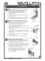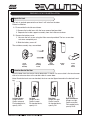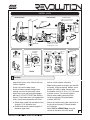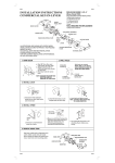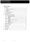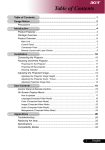
1
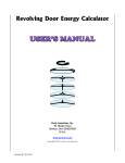
Touchpad Access Cylindrical Lock Installation Instructions INSTALLER NOTE: Failure to follow these instructions could result in damage to the lock and void the factory warranty. For Technical Assistance contact contact ARROW LOCK 1-800-221-6529 • www.arrowlock.com This document is available on our website in printed Spanish and French. Go to www.arrowlock.com. Click "Liternature Req"". Este documento está disponible en español en nuestra página de internet. Vaya a www.arrowlock.com. Presione "Información del Producto y Documentación". Ce document est disponible sur notre site Web dans le français imprimé. Allez à www.arrowlock.com. Cliquez sur le " ; Information sur le produit et Documentation". © ARROW Lock & Door Hardware • 80-9150-0066-010 Rev C TABLE OF CONTENTS Warnings..........................................................................................................................2 Introduction......................................................................................................................2 Installation Components and Tools..............................................................................................3 Door Preparation.......................................................................................................4 Prepare Lock for Installation.................................................................................. 5-6 Install Lock............................................................................................................. 7-8 Hardware Troubleshooting.........................................................................................8 Programming Programming Features-Menus-Keys-Definitions................................................ 9-11 Operating Modes............................................................................................... 12-16 Easy Mode................................................................................................. 12-13 Advanced Mode........................................................................................ 14-16 Miscellaneous Information.......................................................................................17 Programming Troubleshooting................................................................................18 Sample Pin Code Management Sheets..................................................................19 WARNINGS CAUTION: Changes or modifications to this unit not expressly approved by the party responsible for compliance could void the user’s authority to operate the equipment. IMPORTANT: The accuracy of the door preparation is critical for the proper functioning and security of this cylindrical product. Misalignment can cause premature wear and a lessening of security. Finish Care: This lockset is designed to provide the highest standard of product quality and performance. Care should be taken to insure a long-lasting finish. When cleaning is required use a soft, damp cloth. Using lacquer thinner, caustic soaps, abrasive cleaners or polishes could damage the coating and result in tarnishing. INTRODUCTION Arrow® Revolution Stand-alone Touchscreen Access Lock combines robust cylindrical locksets with a contemporary electronic aesthetic. Users benefit from an interactive touchscreen that makes day-to-day access effortless and offers voice-guided programming for simple updates to user information in the event of staffing changes or security breaches. Revolution is engineered for quick and easy installation and fits into the standard ANSI/ BHMA A156.115 cylindrical locks with lever door prep with only one additional 3/4" hole and 7 screws including latchbolt and strike. Revolution features the choice of "Easy" or "Advanced" operating modes. Locks are shipped as a default from the factory in "Easy" mode. The desired operating mode should be determined before the completion of lock installation, but can be changed at a later time if required. 2 © ARROW Lock & Door Hardware • 80-9150-0066-010 Rev C COMPONENTS AND TOOLS In the box, you should find. . . Quick Start Instructions 4 AA Alkaline Batteries Installation Instructions Latchbolt Door Marker Strike Outside Touchscreen Assembly Allen Wrench 3/32" (2.5mm) Inside Escutcheon Assembly: Lever Removal Tool • Inside Support Assembly Screw Pack (7 screws) • Inside Escutcheon 2 Keys (If cylinder included) • Inside Lever Handle • Battery Cover Parts Illustrations Outside Touchscreen Assembly Inside Support Assembly Inside Escutcheon Inside Lever Handle Battery Cover 4 AA Alkaline Batteries Latchbolt Strike Tools Door Prep Lock Installation 2-1/8" (54mm) hole saw #2 phillips screw driver 1" (26mm) boring bit Lever removal tool (supplied) 5/16" (8mm) drill bit 3/8" or 1/2" drill 7/64" (2.5mm) drill bit 3/32" Allen wrench (supplied) Chisel and hammer 3 © ARROW Lock & Door Hardware • 80-9150-0066-010 Rev C DOOR PREPARATION 3/4" Diameter Mark Door Verify backset before marking and drilling door. 3-1/2" A. Mark horizontal line across edge of door 40-5/16" (1024mm) from floor. B. Fold door marker over the edge of the door, centering on the horizonal line. A C. Mark centers of holes at proper backset. For beveled and square edge doors, mark both sides of the door. B C Drill Door Backset 2-3/8" or 2-3/4" A. Drill 2-1/8" (54mm) dia. hole through the door. Cut notches as shown on template. B Note: To avoid splintering wood doors, drill holes (A) and (D) from both sides of the door. B. Drill 3/4" (19mm) diameter hole through the door according to door marker. C. Drill 1" (25mm) diameter hole in edge of door. Mortise for latchbolt front 1-1/8" (29mm) wide x 2-1/4" (57mm) high by 5/32" deep. A D C E D. Drill two (2) 5/16" (8mm) diameter holes through door (see note, above). E. Drill pilot holes for latchbolt screws. 7/64" (2.5mm). Strikes Prepare and Install Strike (Wood Frames Only) V18 Standard Strike Box A. Close the door and mark a horizontal line from the center of the template to the frame of the door. B. Measure half the thickness of the door. Mark this same distance with a vertical line starting from the stop side of the frame. Where both lines cross make a 1" (25mm) diameter hole, 1/2" (13 mm) in depth. C. Align the holes of the strike with the vertical line. Trace the outline of the strike and mortise with a 1/16" (1.6mm) depth. Attach the strike with two screws (provided). Attaching Screws 81-2012-0416 #8-8-32x3/4" V14 Optional Strike Box #V10 Attaching Screws 81-2012-0620 #12-12-24x1" 4 © ARROW Lock & Door Hardware • 80-9150-0066-010 Rev C PREPARE LOCK FOR INSTALLATION Unpack the Lock The lock is packed representative of how it will install on the door. Before installation: A. Disassemble the inside escutcheon 1. Remove the inside lever with the lever removal tool provided 2. Separate the inside support assembly from the inside escutcheon B. Remove the battery cover 1. Unscrew the hex screw using the Allen wrench provided. The hex screw does not come completely out. 2. Slide the battery cover off. The outside assembly stays assembled. Inside Support Assembly Support Assembly Screws Inside Escutcheon Battery Cover Inside Lever Handle Determine Hand of the Door Face the door from the secure side to determine it’s hand. The secure side is the touchscreen side of an entrance door or the corridor side of a room door. Note: Revolution locks are non-handed; the lever can be flipped around to the desired handing. Left Hand Reverse Hinges on left. Opens outward. For handed locks, specify LHR. Left Hand Hinges on left. Opens inward. For handed locks, specify LH. Right Hand Hinges on right. Opens inward. for handed locks, specify RH. Right Hand Reverse Hinges on right. Opens outward. For handed locks, specify RHR. 5 © ARROW Lock & Door Hardware • 80-9150-0066-010 Rev C Adjust Lock for Door Thickness (If Necessary) A Lock is packed pre-adjusted for 1-3/4" (44mm) doors. To adjust for thinner door: B A. Remove (2) screws from outside support assembly. B. Slide outside assembly away from the lock body. F C. Disengage plate from assembly by sliding to the side and removing. G D. Re-seat plate on outside assembly. Plate hole is slightly off center (gray area). Slide plate over assembly and slide to the center until seated in one of the two grooves. E. Adjust for door thickness by D seating plate in grooves on assembly to match door thickness. C Slide Plate to re-seat in grooves F. Re-seat plate on assembly. E Position for 1-3/4" thick doors Position for 1-3/8" thin doors G. Fasten plate and outside assembly to lock body with (2) screws. How to Replace, Re-Key or Install Cylinder 1. Remove cylinder handle: A. Insert key and rotate 45 degrees counterclockwise. B. Insert lever retainer tool and push. C. Slide lever off lock. 2. Remove the plastic sleeve from the old cylinder. 3. Slide new cylinder into sleeve. C 4. Insert key into cylinder. Important: Make sure the key cut side of key lines up facing towards the end of the lever. If the key is inserted incorrectly, the lock will reassemble and might appear to properly work; however, when the key is removed, the latchbolt will remain retracted. ut yc Ke B A 5. Rotate key 45 degrees counterclockwise. Depress retainer plate, push the handle onto the shank until fully seated. Pull on handle to insure properly seated. 2-5/8" (66.5) For 6 pin cylinders, 1-3/8" thick doors 2-7/8" (73) For 6 pin cylinders, 1-3/4" thick doors ONLY 1-3/16" (30) For 6 pin cylinders, 1-3/8" thick doors 1-7/16" (36.5) For 6 pin cylinders, 1-3/4" thick doors ONLY CAUTION: The cylinders furnished with Revolution lock for use in 1-3/8" doors have a tailpiece that is 1/4" shorter than the standard cylinders that are furnished for 1-3/4" doors. Trying to 6 install a standard cylinder in 1-3/8" will DAMAGE the lock body. © ARROW Lock & Door Hardware • 80-9150-0066-010 Rev C INSTALL LOCK Inside Assembly Outside Assembly Escutcheon Screw (1) 10-32 x 3/4" Pan Head With Star Washer Screw Touchscreen Cable 9 3b 13 12 3 10 5 3a 1 1 4 Motor Cable Retractor Engages Bolt Tail(s) Latch 11 Support Assembly Screws (2) 10-32 x 2-1/2" Flat Head Machine Screws 8 Easy / Advanced Mode 7 Touchscreen Cable Connector 9b Touchscreen Cable Routing "Z" Fold (2) 8-32 x 3/4" Flat Head Combination Screws 2 (2) 8-32 x 3/4" Flat Head Combination Screws Frame Engages Latchcase Lock Body Detail A EASY ADVANCED EXT-PWR / REMOTE / MOTOR 6 EXT-PWR / REMOTE / MOTOR Directions 1. Install latchbolt in door. Be sure that bevel edge of bolt faces strike. Attach with two screws supplied. 2. Install strike on the door frame. 4. Guide motor cable through rectangular hole on inside support assembly. 5. Slide inside support assembly over outside assembly, lining up top and bottom screw guides with holes in door. Secure both assemblies with (2) 10-32 x 2-1/2" flat head machine screws. Do not over-tighten. 3. Insert outside assembly through door, making sure that the lock body frame hooks latch case and retractor engages bolt tail(s). DO NOT FORCE (See Detail A 6. Attach motor cable connector to the above). If lock body does not engage latch inside escutcheon PC board header easily, check door preparation for errors. marked “MOTOR.” a. Guide motor cable (red and black wires) 7. Attach the touchscreen cable connector to through 2-1/8" diameter hole. the inside escutcheon PC board header as illustrated. b. Guide touchscreen cable through 3/4" diameter upper hole. 8. Select EASY or ADVANCED Mode using the switch on the back of the PC board. 7 © ARROW Lock & Door Hardware • 80-9150-0066-010 Rev C Directions, Continued 9. Slide inside escutcheon over inside support assembly. CAUTION: a. Position motor cable against inside support assembly. Avoid pinching wires against the steel shank of the assembly. b. “Z” fold touchscreen wire cable and lay against the back recessed area of the escutcheon assembly. Position and bend wires to prevent binding when installing the escutcheon over the support assembly. 10. Install and secure the 10-32 x 3/4" pan head screw through the center of the battery housing into the barrel nut of the outside assembly. 11. Slide on inside lever and push in to attach. 12. Insert four (4) AA alkaline batteries. The lock responds, “Welcome to the Arrow Digital World.” Note: Refer to programming instructions prior to completion of step 13. 13. Install battery cover and tighten hex head screw with Allen wrench provided with lock. HARDWARE TROUBLESHOOTING Test the Operation of the Lockset Cycle the lock in both the locked and the unlocked positions. If problems are found: Symptom Door is binding Suggested Action a.Check that door and frame are properly aligned and door is free swinging. b. Check hinges: They should not be loose or have excessive wear on knuckles. Latchbolt will not deadlock a. Either strike is out of alignment or the gap between the door and jamb is too great. Realign strike or shim strike out towards flat area of latchbolt. Latchbolt does not retract or extend properly Latchbolt tail and retractor are not properly positioned: a. Remove lockset. Look though 2-1/8" hole and verify latchbolt tail is centered between top and bottom of hole. b. Remove latchbolt and insert lockset. Look though latchbolt hole and verify retractor mouth centered in hole. If not, adjust outside rose plate. c. If necessary, rebore holes to line up retractor and tail. 8 © ARROW Lock & Door Hardware • 80-9150-0066-010 Rev C PROGRAMMING Programming Features-Menus-Keys-Definitions................................................ 9-11 Operating Modes............................................................................................... 12-16 Easy Mode................................................................................................. 12-13 Advanced Mode........................................................................................ 14-16 Miscellaneous Information.......................................................................................17 Programming Troubleshooting................................................................................18 Sample Pin Code Management Sheets..................................................................19 PROGRAMMING FEATURES - MENUS - KEYS - DEFINITIONS Inside Outside Numbers HEX Screw " P " Key (Reurn to Previous) Battery Cover " I " Button Touchscreen Low Battery 4 AA Alkaline Batteries Passage Mode Lockout Mode Cylinder Speaker Status LED 9 Volt Emergency Power Supply Terminal 9 Volt Batteries Purchased Separately 9 © ARROW Lock & Door Hardware • 80-9150-0066-010 Rev C Menu and Icons Touch the screen with palm of hand or fingers to begin and end actions. ~ Click the indicated number. Press the Star key on the touchscreen to Enter or Accept entry. 1 Low Battery M Enter Master PIN code (6 digits in length). Advanced Mode only. Factory default: 123456. S Enter Supervisor PIN code. Can be 4-12 digits in length. Factory default: 1234567890. U Enter User PIN. Can be 4-12 digits in length. Press the Pound key on the touchscreen to enter Menu mode. Supervisor Serial Number (00 - 19). Advanced Mode only. Press this key to return to the previous step or menu setting. User Serial Number (01 - 49). Advanced mode only. Repeat operation using settings indicated. Enter value 1 - 10 (times or seconds). The I-Button is located under the battery cover. Remove battery cover for access. Enter value 1 - 255 (seconds). Slide the batter cover up and off. Voice guide. 2 Passage Mode 3 Lockout Mode 4 Return to Previous Step 5 Lock and Unlock - Audio and Visual Definitions Advanced Mode: See "Advanced Mode" on page 14. All Code Lockout: Advanced mode only. This feature is enabled only by the Master code. When enabled, it restricts all user PIN code access. When the unit is in Lockout, the red locked padlock will appear on the screen. Easy Mode: See "Easy Mode" on page 12. Emergency Power Supply: 9V battery connections are located under the front of the outside escutcheon. In the case that the 4 AA alkaline batteries are completely discharged, a 9V battery can be used to supply power to the lock. While connecting the 9V battery, the lock can be operated as normal, thus granting access so the 4 AA alkaline batteries can be replaced. Group Lockout: Advanced mode only. This feature can be enabled by either the Master code or the Supervisor code. If Group Lockout is enabled through the Master code, specific Supervisors and their entire group of Users will be locked out. If Group Lockout is enabled through the Supervisor code, only Users corresponding to that Supervisor are locked out. 10 © ARROW Lock & Door Hardware • 80-9150-0066-010 Rev C Definitions I-Button: Easy mode only. Located under the battery cover, the “I” button is used for changing the default Supervisor code and can be used for programming. Low Battery: When battery power is low, the low battery icon will begin blinking. If battery power is completely lost, the emergency power supply can be used. Operating Modes: Revolution features the choice of Easy or Advanced operating modes. The desired operating mode should be determined before the completion of lock installation, but can be changed at a later time if required. Passage Mode: Easy and Advanced mode. Enabling Passage mode allows continuous entry for non-restricted traffic. Passage mode is enabled or disabled through feature programming by either the Master or Supervisor code. When the unit is in Passage Mode, the green unlocked padlock will appear on the screen. Master Code: Advanced mode only. The Master code is used for programming Supervisor codes and also for feature settings. The Master code will not operate the lock. Re-lock Time: After successful code entry and the unit unlocks, it will automatically relock after a default of five (5) seconds. Re-lock time is adjustable from one (1) to ten (10) seconds in Advanced mode only through feature settings. Shut Down Time: The unit will shut down for a default of one hundred and eighty (180) seconds and not allow operation after the wrong code entry limit has been met. Shut down time is adjustable from one (1) to two hundred and fifty-five (255) seconds in Advanced mode only through feature settings. When the unit is in Shut Down, the red locked padlock icon will be flashing. Silent Mode: Easy and Advanced mode. Enabling Silent mode shuts off the code confirmation tone playback for use in quiet areas. Silent mode is enabled or disabled through feature programming by either the Master or Supervisor code. Status LED: Located on inside escutcheon. Flashes green to indicate lock in Passage mode. Supervisor Code: Easy and Advanced mode. The Supervisor code is used for programming User codes and also for feature settings. The Supervisor code will operate the lock. User Code: Easy and Advanced mode. The User code is used for operating the lock. User Lockout: Advanced mode only. This feature can be enabled only by the Supervisor code. When enabled, it restricts User PIN code access only for specified User numbers corresponding to that Supervisor. Wrong Code Entry Limit: After a default of five (5) unsuccessful attempts at entering a valid PIN code the unit will shut down and not allow operation. Wrong code entry limit is adjustable from one (1) to ten (10) times in Advanced mode only through feature settings. 11 © ARROW Lock & Door Hardware • 80-9150-0066-010 Rev C OPERATING MODES Easy Mode Provides a simple, easy-to-use system for general use. In Easy mode, a total of 9 PIN codes are available for access. Code assignments consist of one (1) Supervisor code and eight (8) User codes. Initial programming is performed by the use of the button (located under the battery cover of the inside escutcheon) and voice guided instruction. Subsequent changes to programming can be performed through the touchscreen by the use of the Supervisor code. While in Easy mode, the lock can be programmed for Passage mode, Silent mode or alternate Language settings. Auto Re-lock time, wrong code entry limits and shut down times are not adjustable and will remain as factory default. Note: After initial set-up, individual User PIN codes can not be added to or deleted from programming. Upon entering the Register/Change user code function, ALL existing User codes are deleted and must be re-entered if needed. The operating mode can be changed from Easy to Advanced or visa versa for any lock. Changing the mode resets the lock to factory defaults and all prior programming and PIN codes will be lost. See page 17 for more information. Supervisor User 1 User 2 User 3 User 4 User 5 User 6 User 7 User 8 Feature Supervisor User Settings Factory Defaults Entrance Authorization x x Supervisor Code 1234567890 Register/Change User Code x Passage Mode Disabled Set Passage Mode x Silent Mode Disabled Set Silent Mode x Re-lock Time 5 Seconds Set Language Setting Mode x Wrong Code Entry Limit 5 Times Shut Down Time 180 Seconds Language English Programming I-Button Set/Change Supervisor PIN x Set/Change User PIN (1 - 8) x Touchscreen x Operation of Lock Touch lock with palm of hand or fingers to activate. key Enter PIN code. Palm or touch the to confirm the selection. Turn lever to open door. 12 © ARROW Lock & Door Hardware • 80-9150-0066-010 Rev C Register / Change PIN Codes (including Supervisor Code) through I-Button 1 2 Unscrew battery cover hex screw using tool provided. Slide battery cover up and off to reveal the button located above the batteries. Press the time. 3 button one Enter the new Supervisor PIN code (4 to 12 digits), followed by the key. Lock Response: “Register User code. Enter one Supervisor then up to 8 users. Enter a 4 to 12 digit PIN code, each followed by the key. Press the button to complete.” 1 4 Lock Response: Sounds a tone for each PIN code digit with digits flashing in the sequence entered to confirm the entry. Chime signals when playback is complete. 5 Enter the first User PIN code (4 12 digits) followed by the key. Press the button to complete the process after the last playback sequence. Lock Response: “Registered." Lock Response: Sounds a tone for each PIN code digit with digits flashing in the sequence entered to confirm the entry. Chime signals when playback is complete. Continue to enter add User PIN codes (4 to 12 digits each) followed by the key. Up to eight User PIN codes can be entered. 2 3 4 5 U S 1-8 Feature Programming Through Menu Mode via Supervisor Code 1. Touch the screen with the palm of your hand or fingers to acitivate . 2. Enter the 4-12 digit Supervisor PIN code followed by the key. Lock Response: “Menu mode, enter number, press the key to continue.” 3. Enter digit corresponding to the function to be performed followed by the key. Follow the verbal commands. 4. Press the key to complete the process and conclude the programming session. 1 2 S 3 4 U Register User Code 1-8 Passage Mode Enable Disable Silent Mode Enable Disable Language Setting Mode Note: When registering User codes, the code must be entered with in 20 seconds. If time expires, no codes are registered and the process must be re-started. English Spanish French 13 © ARROW Lock & Door Hardware • 80-9150-0066-010 Rev C Advanced Mode Provides a 3-tier PIN code system for commercial use. In Advanced mode, a total of 1,000 PIN codes are available for access. The 1,000 PIN codes are divided into twenty (20) Supervisor groups of fifty (50) User codes per group. Advanced mode also has a Master code which is used only for programming and does not grant access. Master 00 Supervisor 04 Supervisor 09 Supervisor 19 Supervisor 01 User 01 User 01 User 02 User 02 User 02 User 03 User 03 User 03 User 48 User 48 User 48 User 49 User 49 User 49 User Settings Master Entrance Authorization All programming is performed through the touchscreen using the Master or Supervisor code and voice guided prompts. Only the Supervisor code can establish User codes. While in Advanced mode, the lock can be programmed for Passage mode, Silent mode, Lockout mode or alternate Language settings. Auto re-lock time, wrong code entry limits and shut down times are adjustable can be changed from factory default. The operating mode can be changed from Advanced to Easy or visa versa for any lock. Changing the mode resets the lock to factory defaults and all prior programming and PIN codes will be lost. See page 17 for more information. Supervisor User x x Settings Factory Defaults Master Code 123456 Register/Change Master Code x Lockout Mode Disabled Register/Change/Delete Supervisor Code x Passage Mode Disabled Silent Mode Disabled Re-lock Time 5 Seconds Register/Change/Delete User Code x Set All Code Lockout Mode x Set Group Lockout Mode x Set User Lockout Mode x Wrong Code Entry Limit x Shut Down Time Language Set Passage Mode x x Set Silent Mode x x Set Re-lock Time x Set Wrong Code Entry Limit x Set Shut Down Time x Set Language Setting Mode x 5 Times 180 Seconds English Operation of Lock Touch lock with palm Enter PIN code. Palm or touch the key of hand or fingers to confirm the selection. to activate. Turn lever to open door. 14 © ARROW Lock & Door Hardware • 80-9150-0066-010 Rev C Change Default Master Code Before Programming 1. Touch the screen with the palm of your hand or fingers to activate . 2. Enter the 6-digit default Master PIN code (123456) followed by the Lock Response: “Menu mode, enter number, press the 3. Enter “1” followed by the key to continue.” key. 4. Enter new 6-digit Master PIN code followed by the 5. Press key. key. key to complete the process and conclude the programming session. Feature Programming Through Master Code 1. Touch the screen with the palm of your hand or fingers to acitivate 2. Enter the 6-digit Master PIN code followed by the . key. Lock Response: “Menu mode, enter number, press the key to continue.” 3. Enter digit corresponding to the function to be performed followed by the key. Follow the verbal commands. 4. Press the 1 key to complete the process and conclude the programming session. 2 M 3 Register Master Code Register Supervisor Code 4 M Register S 00-19 Delete All Code Lockout Mode Enable Disable Group Lockout Mode Enable 00-19 Disable 00-19 Passage Mode Enable Disable Silent Mode Enable Disable Lock Setting Mode Re-lock Time Wrong Code Entry Limit Shut Down Time Language Setting Mode English Spanish French 15 © ARROW Lock & Door Hardware • 80-9150-0066-010 Rev C Set Up Supervisor Codes 1. Touch the screen with the palm of your hand or fingers to acitivate . 2. Enter the 6-digit Master PIN code followed by the key. Lock Response: “Menu mode, enter number, press the key to continue.” 3. Enter "2" followed by the key. 4. Enter "1" followed by the key. 5. Enter the Supervisor number to register (00-19) followed by the key. 6. Enter a 4-12 digit PIN code for the Supervisor number followed by the key. 7. Press the key to complete the process and conclude the programming session. Feature Programming Through Supervisor Code 1. Touch the screen with the palm of your hand or fingers to activate. 2. Enter the 4-12 digit Supervisor PIN code followed by the key. Lock Response: "Menu mode, enter number, press the key to continue." 3. Enter digit corresponding to the function to be performed followed by the key. Follow the verbal commands. 4. Press the key to complete the process and conclude the programming session. 1 2 S 3 Register User Code 4 U Register 01-49 Delete Group User Lockout Mode Enable Disable User Code Lockout Mode Enable 01-49 Disable 01-49 Passage Mode Enable Disable Silent Mode Enable Disable To Set Up User Codes User Codes can only be programmed through Supervisor Code. 1. Touch the screen with the palm of your hand or fingers to acitivate . 2. Enter the 4-12 digit Supervisor PIN code followed by the key. Lock Response: “Menu mode, enter number, press the key to continue.” 3. Enter "1" followed by the key. 4. Enter "1" again, followed by the key. 5. Enter the User number to be registered (01-49) followed by the key. 6. Enter a 4-12 digit PIN code for the User number followed by the key. 7. Press the key to complete the process and conclude the programming session. 16 © ARROW Lock & Door Hardware • 80-9150-0066-010 Rev C MISCELLANEOUS INFORMATION To Change Operating Modes Note: Changing the operating mode from Easy to Advanced or vice versa deletes all prior programming. 6 Easy / Advanced Setting The outside assembly remains assembled. 1. Remove inside lever. 2. Remove battery cover using Allen wrench provided with lock. 3. Remove four (4) AA alkaline batteries. 4. Remove the 10-32 x 3/4" pan head screw from the center of the battery housing into the barrel nut of the outside assembly. EASY EXT-PWR / REMOTE / MOTOR 5. Remove inside escutcheon. 6. On the back of the PC board, change the position of the EASY/ADVANCED switch. To reassemble the lock, refer to steps 9 through 13 on page 8. ADVANCED EXT-PWR / REMOTE / MOTOR To Return Lock to Programming Defaults To return the lock to programming defaults without changing the operating mode: 1 - 6. Follow steps 1 through 6 (above). 7. Insert the four (4) AA alkaline batteries. The lock responds, "Welcome to the Arrow Digital World." 8. Remove the batteries. 9. Change the position of the EASY/ADVANCED switch to original state. 10. Reassemble the lock by referring to steps 9 through 13 on page 8. All programming should be returned to factory defaults. Emergency Power Suppy and Battery Replacement 9V battery connections are located under the front of the outside escutcheon. In the case that the 4 AA alkaline batteries are completely discharged, a 9V battery can be used to supply power to the lock. While connecting the 9V battery, the lock can be operated as normal, thus granting access so the 4 AA alkaline batteries can be replaced. Discharged batteries should be replaced right away. 17 © ARROW Lock & Door Hardware • 80-9150-0066-010 Rev C TROUBLESHOOTING Symptom Lock does not respond – door is open and accessible. Suggested Action • The touchscreen will become active when pressed with the palm or fingers in at least 3 areas simultaneously. • Lock does not respond – door is locked and inaccessible. Use a larger area of the palm or fingers and verify contact with at least 3 areas. • If touchscreen numbers are visible, check to see if they respond when pressed. • Check batteries are installed and oriented correctly in the battery case. • Check batteries are in good condition; replace batteries if discharged (page 17). • Check to see if touchscreen cable is properly connected and not pinched (page 7). • Batteries may be completely discharged. • Use mechanical key to gain entry and replace batteries. • Connect a 9-volt battery to the emergency power supply terminal which is located on the outside escutcheon, under the lever. With the 9-volt battery connected, palm the touchscreen, enter PIN code, and palm touchscreen again (page 17). Replace batteries. The unit is on for a while, and then shows no reaction. Lights dim. • The batteries do not have enough power. Replace the batteries. Unit chimes to indicate code acceptance, but the door will not open. • Check to see if there is another locking device on the door (i.e. deadbolt). • Check the door gaps for any foreign objects between door and frame. • Check that the motor cable is firmly connected to the PC board header marked “MOTOR” (page 7). • Check to see if Passage Mode is enabled (pages 15-16). Unit operates to allow access, but will not automatically re-lock. • If the Passage Mode icon on the touchscreen and the status indicator on the • interior escutcheon flicker for several seconds, it is set at Passage Mode (page 9). Disable Passage Mode to lock the door. • If low battery indicator is lit (page 10), change batteries. • PIN codes must consist of 4 to 12 digits to register. • The same PIN code cannot be used for multiple users. • In Advanced Mode, registration/management of PIN codes is set at the authority of Master and/or Supervisor. • In Advanced mode, the Master PIN code does not unlock the door. • In Easy Mode, User codes must be entered within 20 seconds (while the touchscreen is active) or the process will have to be restarted. • In Easy Mode, the Supervisor PIN code can only be registered using the I-Button. • The star (*) or pound (#) can not be used as part of the PIN code. Upon entering a PIN code and pressing the star (*) key, the unit displays and “invalid code” error or the lock times out without responding. • Either All Code, Group or User Lockout Mode is enabled (15-16). • Only the Master or Supervisor can enable Lockout Mode. Upon entering a PIN code and pressing the (*) key, the red padlock icon appears and there are different tones. • Check to see if either you or your group is set at Lockout Mode. • Setting/managing Lockout Mode is up to Master and Supervisor. Contact the Master user or Supervisor. The unit operates, but it makes no sound. • Check to see if Silent Mode is enabled (page 13, 15). The unit responds “Low Battery” • This is the voice alarm alerting that it is time to replace the batteries. Replace all four (4) batteries with new AA Alkaline batteries. Upon entering a PIN code and pressing the star (*) key, the unit responds “Wrong digit numbers.” • The digits entered were incorrect or incomplete. Re-enter the code. PIN codes will not register. • • Contact the Master or Supervisor. Contact the Master user or Supervisor. 18 © ARROW Lock & Door Hardware • 80-9150-0066-010 Rev C PIN CODE MANAGEMENT SAMPLE SHEETS Easy Mode PIN Code Management Door Number: Door Number: Name PIN Number User Name Supervisor Supervisor User 1 User 1 User 2 User 2 User 3 User 3 User 4 User 4 User 5 User 5 User 6 User 6 User 7 User 7 User 8 User 8 PIN Number Advanced Mode PIN Code Management Location: User Type Door Number: User Name Group # User # User PIN Code User Name Group # User # PIN Code User 24 Master User 25 Supervisor User 26 User 01 User 27 User 02 User 28 User 03 User 29 User 04 User 30 User 05 User 31 User 06 User 32 User 07 User 33 User 08 User 34 User 09 User 35 User 10 User 36 User 11 User 37 User 12 User 38 User 13 User 39 User 14 User 40 User 15 User 41 User 16 User 42 User 17 User 43 User 18 User 44 User 19 User 45 User 20 User 46 User 21 User 47 User 22 User 48 User 23 User 49 19 © ARROW Lock & Door Hardware • 80-9150-0066-010 Rev C ARROW USA 100 Arrow Drive, New Haven,CT 06536-0915 Phone: (800) 839-3157 Fax: (800) 421-6615 [email protected] Orders & Customer Service: Arrow Lock & Door Hardware P.O. Box 3075 Salem, VA 24153 Phone USA: 800-839-3157 Fax: 800-421-6615 Phone Canada: 905-738-2466 Fax: 905-738-2678 Invoice Payments Only Arrow Lock Accounts Receivable P.O. Box 640711 Pittsburgh, PA 15264 Return Goods Only (RGA# Required) Arrow Lock & Door Hardware 100 Arrow Lock Drive New Haven, CT 06511 Arrow Architectural Hardware ARROW® is a registered trademark of Arrrow Architectural Hardware, an ASSA ABLOY Group company. Revolution™ is a trademark of Arrrow Architectural Hardware, an ASSA ABLOY Group company. Other products’ brand names may be trademarks or registered trademarks of their respective owners and are mentioned for reference purposes only. These materials are protected under U.S. copyright laws. All contents current at time of publication. Arrow Architectural Hardware., an ASSA ABLOY Group company, reserves the right to change availability of any item in this catalog, its design, construction, and/or its materials. Copyright © 2009, Arrow Architectural Hardware, an ASSA ABLOY Group company. All rights reserved. Reproduction in whole or in part without the express written permission of Arrow Architectural Hardware is prohibited. © ARROW Lock & Door Hardware • 80-9150-0066-010 Rev C