1
PV Inverter
SUNNY TRIPOWER 15000TL Economic Excellence
SUNNY TRIPOWER 15000TL High Efficiency
SUNNY TRIPOWER 20000TL Economic Excellence
SUNNY TRIPOWER 20000TL High Efficiency
Installation Manual
STP20TLHE-IA-IEN122222 | IMEN-STP20TLHE | Version 2.2
EN
SMA Solar Technology AG
Table of Contents
Table of Contents
1
1.1
1.2
1.3
1.4
Information on this Manual. . . . . . . . . . . . . . . . . . . . . . . . .
Validity . . . . . . . . . . . . . . . . . . . . . . . . . . . . . . . . . . . . . . . . . . . .
Target Group . . . . . . . . . . . . . . . . . . . . . . . . . . . . . . . . . . . . . . .
Additional Information . . . . . . . . . . . . . . . . . . . . . . . . . . . . . . . .
Symbols Used . . . . . . . . . . . . . . . . . . . . . . . . . . . . . . . . . . . . . . .
2
2.1
2.2
2.3
Safety . . . . . . . . . . . . . . . . . . . . . . . . . . . . . . . . . . . . . . . . . . 9
Intended Use. . . . . . . . . . . . . . . . . . . . . . . . . . . . . . . . . . . . . . . . 9
Safety Precautions. . . . . . . . . . . . . . . . . . . . . . . . . . . . . . . . . . . 10
Explanation of Symbols . . . . . . . . . . . . . . . . . . . . . . . . . . . . . . 11
2.3.1
Symbols on the Inverter. . . . . . . . . . . . . . . . . . . . . . . . . . . . . . . . . . . . . . . . . 11
2.3.2
Symbols on the Type Label . . . . . . . . . . . . . . . . . . . . . . . . . . . . . . . . . . . . . . 11
3
3.1
3.2
Unpacking. . . . . . . . . . . . . . . . . . . . . . . . . . . . . . . . . . . . . . 13
Scope of Delivery . . . . . . . . . . . . . . . . . . . . . . . . . . . . . . . . . . . 13
Identifying the Inverter . . . . . . . . . . . . . . . . . . . . . . . . . . . . . . . 14
4
4.1
4.2
4.3
4.4
4.5
4.6
4.7
Product Description . . . . . . . . . . . . . . . . . . . . . . . . . . . . . . 15
Sunny Tripower . . . . . . . . . . . . . . . . . . . . . . . . . . . . . . . . . . . . . 15
Display . . . . . . . . . . . . . . . . . . . . . . . . . . . . . . . . . . . . . . . . . . . 16
DC switch-disconnector. . . . . . . . . . . . . . . . . . . . . . . . . . . . . . . 18
Communication. . . . . . . . . . . . . . . . . . . . . . . . . . . . . . . . . . . . . 18
Multi-Function Relay . . . . . . . . . . . . . . . . . . . . . . . . . . . . . . . . . 19
Feed-In Management . . . . . . . . . . . . . . . . . . . . . . . . . . . . . . . . 19
Reverse Current Protection . . . . . . . . . . . . . . . . . . . . . . . . . . . . 20
5
5.1
5.2
5.3
Mounting. . . . . . . . . . . . . . . . . . . . . . . . . . . . . . . . . . . . . . . 21
Safety . . . . . . . . . . . . . . . . . . . . . . . . . . . . . . . . . . . . . . . . . . . . 21
Selecting the Mounting Location. . . . . . . . . . . . . . . . . . . . . . . . 21
Mounting the Inverter . . . . . . . . . . . . . . . . . . . . . . . . . . . . . . . . 23
Installation Manual
STP20TLHE-IA-IEN122222
7
7
7
7
8
3
Table of Contents
SMA Solar Technology AG
6
6.1
6.2
6.3
Electrical Connection . . . . . . . . . . . . . . . . . . . . . . . . . . . . . 27
Safety . . . . . . . . . . . . . . . . . . . . . . . . . . . . . . . . . . . . . . . . . . . . 27
Overview of the Connection Area . . . . . . . . . . . . . . . . . . . . . . 27
Connection to the Electricity Grid (AC). . . . . . . . . . . . . . . . . . . 29
6.3.1
Conditions for the AC Connection . . . . . . . . . . . . . . . . . . . . . . . . . . . . . . . . 29
6.3.2
AC Connection Procedure . . . . . . . . . . . . . . . . . . . . . . . . . . . . . . . . . . . . . . 31
6.3.3
Connecting the Second Protective Conductor. . . . . . . . . . . . . . . . . . . . . . . . 33
6.4
Connecting the PV Array (DC) . . . . . . . . . . . . . . . . . . . . . . . . . 34
6.4.1
Conditions for DC Connection . . . . . . . . . . . . . . . . . . . . . . . . . . . . . . . . . . . 34
6.4.2
Assembling the DC Connectors. . . . . . . . . . . . . . . . . . . . . . . . . . . . . . . . . . . 36
6.4.3
Opening the DC Connector . . . . . . . . . . . . . . . . . . . . . . . . . . . . . . . . . . . . . 38
6.4.4
Connecting the PV Array (DC) . . . . . . . . . . . . . . . . . . . . . . . . . . . . . . . . . . . 39
6.5
Setting the Country Data Set and Display Language . . . . . . . . 42
6.5.1
Checking the Country Data Set. . . . . . . . . . . . . . . . . . . . . . . . . . . . . . . . . . . 44
6.5.2
Extension of the Deactivation Limits. . . . . . . . . . . . . . . . . . . . . . . . . . . . . . . . 48
6.5.3
Setting the country data set and language using rotary switches . . . . . . . . . 49
6.6
Communication. . . . . . . . . . . . . . . . . . . . . . . . . . . . . . . . . . . . . 50
6.6.1
Bluetooth . . . . . . . . . . . . . . . . . . . . . . . . . . . . . . . . . . . . . . . . . . . . . . . . . . 50
6.6.2
Multi-Function Interface . . . . . . . . . . . . . . . . . . . . . . . . . . . . . . . . . . . . . . . . . 51
6.6.3
Communication Interface . . . . . . . . . . . . . . . . . . . . . . . . . . . . . . . . . . . . . . . 51
6.7
Activating and Deactivating the Reverse Current Protection
at Input Area A . . . . . . . . . . . . . . . . . . . . . . . . . . . . . . . . . . . . . 52
7
7.1
7.2
Commissioning . . . . . . . . . . . . . . . . . . . . . . . . . . . . . . . . . . 55
Commissioning the Inverter . . . . . . . . . . . . . . . . . . . . . . . . . . . . 55
Display Messages during the Start Phase. . . . . . . . . . . . . . . . . 57
8
Disconnecting the Inverter from Voltage Sources . . . . . . 58
9
9.1
9.2
Maintenance and Cleaning . . . . . . . . . . . . . . . . . . . . . . . . 61
Cleaning the Inverter. . . . . . . . . . . . . . . . . . . . . . . . . . . . . . . . . 61
Checking Heat Dissipation . . . . . . . . . . . . . . . . . . . . . . . . . . . . 61
4
STP20TLHE-IA-IEN122222
Installation Manual
SMA Solar Technology AG
Table of Contents
9.2.1
Cleaning the Ventilation Grids . . . . . . . . . . . . . . . . . . . . . . . . . . . . . . . . . . . 61
9.2.2
Cleaning the Fan on the Bottom of the Inverter. . . . . . . . . . . . . . . . . . . . . . . 62
9.2.3
Cleaning the Fan on the Left-hand Side of the Inverter Enclosure . . . . . . . . . 64
9.2.4
Checking the Fans. . . . . . . . . . . . . . . . . . . . . . . . . . . . . . . . . . . . . . . . . . . . . 65
10
10.1
10.2
10.3
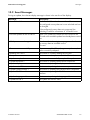
Messages . . . . . . . . . . . . . . . . . . . . . . . . . . . . . . . . . . . . . . 66
LED Signals . . . . . . . . . . . . . . . . . . . . . . . . . . . . . . . . . . . . . . . . 66
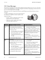
Event Messages . . . . . . . . . . . . . . . . . . . . . . . . . . . . . . . . . . . . 67
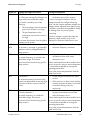
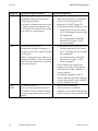
Error Messages. . . . . . . . . . . . . . . . . . . . . . . . . . . . . . . . . . . . . 68
11
11.1
11.2
Troubleshooting . . . . . . . . . . . . . . . . . . . . . . . . . . . . . . . . . 75
Checking the PV Array for Earth Faults . . . . . . . . . . . . . . . . . . . 75
Checking the Function of the Varistors . . . . . . . . . . . . . . . . . . . 77
12
12.1
12.2
12.3
12.4
12.5
Decommissioning . . . . . . . . . . . . . . . . . . . . . . . . . . . . . . . . 81
Dismantling the Inverter. . . . . . . . . . . . . . . . . . . . . . . . . . . . . . . 81
Replacing the Enclosure Lid . . . . . . . . . . . . . . . . . . . . . . . . . . . 82
Packing the Inverter. . . . . . . . . . . . . . . . . . . . . . . . . . . . . . . . . . 84
Storing the Inverter . . . . . . . . . . . . . . . . . . . . . . . . . . . . . . . . . . 84
Disposing of the inverter . . . . . . . . . . . . . . . . . . . . . . . . . . . . . . 84
13
13.1
Technical Data . . . . . . . . . . . . . . . . . . . . . . . . . . . . . . . . . . 85
DC/AC . . . . . . . . . . . . . . . . . . . . . . . . . . . . . . . . . . . . . . . . . . . 85
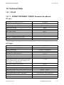
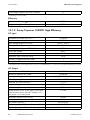
13.1.1
SUNNY TRIPOWER 15000TL Economic Excellence . . . . . . . . . . . . . . . . . . 85
13.1.2
Sunny Tripower 15000TL High Efficiency. . . . . . . . . . . . . . . . . . . . . . . . . . . 86
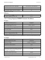
13.1.3
13.1.4
Sunny Tripower 20000TL Economic Excellence . . . . . . . . . . . . . . . . . . . . . . 87
Sunny Tripower 20000TL High Efficiency. . . . . . . . . . . . . . . . . . . . . . . . . . . 88
13.2
13.3
13.4
13.5
13.6
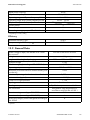
General Data . . . . . . . . . . . . . . . . . . . . . . . . . . . . . . . . . . . . . . 89
Protective Devices . . . . . . . . . . . . . . . . . . . . . . . . . . . . . . . . . . . 90
Licences. . . . . . . . . . . . . . . . . . . . . . . . . . . . . . . . . . . . . . . . . . . 90
Climatic Conditions . . . . . . . . . . . . . . . . . . . . . . . . . . . . . . . . . . 91
Features . . . . . . . . . . . . . . . . . . . . . . . . . . . . . . . . . . . . . . . . . . 91
Installation Manual
STP20TLHE-IA-IEN122222
5
Table of Contents
SMA Solar Technology AG
13.7
13.8
13.9
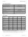
Torque. . . . . . . . . . . . . . . . . . . . . . . . . . . . . . . . . . . . . . . . . . . . 91
Distribution systems . . . . . . . . . . . . . . . . . . . . . . . . . . . . . . . . . . 91
Data Storage Capacity. . . . . . . . . . . . . . . . . . . . . . . . . . . . . . . 92
14
Accessories . . . . . . . . . . . . . . . . . . . . . . . . . . . . . . . . . . . . . 93
15
Contact . . . . . . . . . . . . . . . . . . . . . . . . . . . . . . . . . . . . . . . . 94
6
STP20TLHE-IA-IEN122222
Installation Manual
SMA Solar Technology AG
Information on this Manual
1 Information on this Manual
1.1 Validity
This manual describes the procedure for mounting, installation, commissioning, maintenance and
troubleshooting of the following SMA inverters:
• Sunny Tripower 15000TL Economic Excellence (STP 15000TLEE-10)
• Sunny Tripower 15000TL High Efficiency (STP 15000TLHE-10)
• Sunny Tripower 20000TL Economic Excellence (STP 20000TLEE-10)
• Sunny Tripower 20000TL High Efficiency (STP 20000TLHE-10)
Store this manual where it will be accessible at all times.
1.2 Target Group
This manual is for the use of electrically skilled persons. The tasks described in this manual may be
performed by electrically skilled persons only.
1.3 Additional Information
You will find further information on special topics such as designing a miniature circuit-breaker or the
description of the parameters and measured values at www.SMA.de/en.
Refer to the user manual provided for detailed information on how to operate the inverter.
Installation Manual
STP20TLHE-IA-IEN122222
7
Information on this Manual
SMA Solar Technology AG
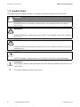
1.4 Symbols Used
The following types of safety precautions and general information appear in this document:
DANGER!
DANGER indicates a hazardous situation which, if not avoided, will result in death or
serious injury.
WARNING!
WARNING indicates a hazardous situation which, if not avoided, could result in death or
serious injury.
CAUTION!
CAUTION indicates a hazardous situation which, if not avoided, could result in minor or
moderate injury.
NOTICE!
NOTICE indicates a situation which, if not avoided, could result in property damage.
Information
An Information block provides valuable hints for the efficient installation and operation of
your product.
☑
8
This symbol indicates the result of an action.
STP20TLHE-IA-IEN122222
Installation Manual
SMA Solar Technology AG
Safety
2 Safety
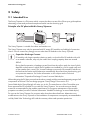
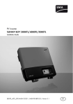
2.1 Intended Use
The Sunny Tripower is a PV inverter which converts the direct current of the PV array to grid-compliant
alternating current and performs three-phase feed-in into the electricity grid.
Principle of a PV plant with this Sunny Tripower
The Sunny Tripower is suitable for indoor and outdoor use.
The Sunny Tripower may only be operated with PV arrays (PV modules and cabling) of protection
class II. Do not connect any energy sources other than PV modules to the Sunny Tripower.
Capacitive Discharge Currents
PV modules with large capacities relative to earth, such as thin-film PV modules with cells
on a metallic substrate, may only be used if their coupling capacity does not exceed
500 nF.
During feed-in operation, a leakage current flows from the cells to earth, the size of which
depends on the manner in which the PV modules are installed (e.g. foil on metal roof) and
on the weather (rain, snow). This "normal" leakage current may not exceed 50 mA due to
the fact that the inverter would otherwise automatically disconnect from the electricity grid
as a protective measure. For further information on this subject see the Technical
Information "Capacitive Discharge Currents" at www.SMA.de/en.
When designing the PV plant, ensure that the values comply with the permitted operating range of all
components at all times. The free design program "Sunny Design" from version 2.0
(www.SMA.de/en/SunnyDesign) will assist you in this. The manufacturer of the PV modules must
have approved the PV modules for use with this Sunny Tripower. You must also ensure that all
measures recommended by the module manufacturer for long-term maintenance of the module
properties are taken (see also Technical Information "Module Technology" at www.SMA.de/en).
Do not use the Sunny Tripower for purposes other than those described here. Alternative uses,
modifications to the Sunny Tripower or the installation of components not expressly recommended or
sold by SMA Solar Technology AG void the warranty claims and operation permission.
Installation Manual
STP20TLHE-IA-IEN122222
9
SMA Solar Technology AG
Safety
2.2 Safety Precautions
DANGER!
Danger to life due to high voltages in the inverter
High voltages which may cause electric shocks are present in the conductive parts of the
inverter.
• Prior to performing any work on the inverter, disconnect the inverter on the AC and
DC sides (see Section 8 "Disconnecting the Inverter from Voltage Sources"
(page 58)).
CAUTION!
Risk of burns due to hot enclosure parts
During operation, the upper enclosure lid and the enclosure body may become hot.
• Only touch the lower enclosure lid during operation.
PV array earthing
Comply with the local regulations for earthing the modules and the PV array.
SMA Solar Technology AG recommends connecting the array frame and other electrically
conductive surfaces so that there is continuous conduction and earthing them in order to
ensure maximum protection for property and persons.
10
STP20TLHE-IA-IEN122222
Installation Manual
SMA Solar Technology AG
Safety
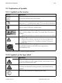
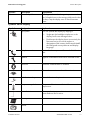
2.3 Explanation of Symbols
2.3.1 Symbols on the Inverter
Symbol
Explanation
Operation display
Indicates the operating state of the inverter.
A disturbance has occurred.
Read section 11 "Troubleshooting" (page 75) to remedy the disturbance.
SMA Bluetooth® Wireless Technology.
Shows the status of Bluetooth communication.
Danger to life due to high voltages in the inverter
There is residual voltage in the inverter. The inverter takes 20 minutes to
discharge.
• Wait 20 minutes before you open the upper enclosure lid or the DC lid.
NOTICE, danger!
• Observe the connection requirements for the second protective
conductor in Section 6.3.1 "Conditions for the AC Connection"
(page 29).
QR Code®* for SMA bonus programme
You will find information on the SMA bonus programme at
www.SMA-Bonus.com.
* QR-Code is a registered trademark of DENSO WAVE INCORPORATED.
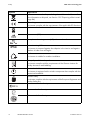
2.3.2 Symbols on the Type Label
Symbol
Explanation
Beware of dangerous voltage.
The inverter operates at high voltages. All work on the inverter must be
carried out by skilled persons only.
Beware of hot surface.
The inverter can become hot during operation. Avoid contact during
operation.
Observe all documentation accompanying the inverter.
Installation Manual
STP20TLHE-IA-IEN122222
11
SMA Solar Technology AG
Safety
Symbol
Explanation
The inverter must not be disposed of together with household waste. For
more information on disposal, see Section 12.5 "Disposing of the inverter"
(page 84).
CE marking
The inverter complies with the requirements of the applicable EC directives.
The inverter does not have a transformer.
Direct current (DC)
Three-phase alternating current (AC) with neutral conductor
IP54
Protection rating IP54.
The inverter is protected against dust deposits in the interior and against
splashes of water from all angles.
Outdoor
The inverter is suitable for outdoor installation.
RAL quality mark for solar products
The inverter complies with the requirements of the German Institute for
Quality Assurance and Labelling.
Device class label
The inverter is equipped with a wireless component that complies with the
harmonised standards.
Certified safety
The inverter complies with the requirements of the European Equipment and
Product Safety Act.
Australian mark of conformity
Korean mark of conformity.
Chinese mark of conformity
12
STP20TLHE-IA-IEN122222
Installation Manual
SMA Solar Technology AG
Unpacking
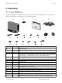
3 Unpacking
3.1 Scope of Delivery
Check the delivery for completeness and for any visible external damage. Contact your specialist
dealer if the delivery is incomplete or you find any damage.
Object
A
B
C
D
Quantity
1
1
1
1
E
F
G
H
I
K
L
M
N
O
P
6
6
12
1
2
1
1
1
1
1
2
Installation Manual
Description
Sunny Tripower
Handle of the DC switch-disconnector*
Back panel
Installation manual including user manual, document set with explanations
and certificates, supplementary sheet with the default settings
Negative DC connector
Positive DC connector
Sealing plugs
Eye bolt M8 for securing the inverter to the back panel
Cheese-head screw M5x10 for attaching the enclosure to the back panel
Cable gland for AC connection
Counter nut for cable gland at AC connection
Clamping bracket M6 for additional earthing
Cheese-head screw M6 for earth terminal
Conical spring washer M6 for earth terminal
Cheese-head screws M5x20 for upper enclosure lid (replacement)
STP20TLHE-IA-IEN122222
13
SMA Solar Technology AG
Unpacking
Object
Q
R
Quantity Description
2
Conical spring washers M5 for upper enclosure lid (replacement)
1
Jumper cable for deactivating the reverse current protection
*optional
3.2 Identifying the Inverter
You can identify the inverter by the type label. The type label is located on the right-hand side of the
enclosure.
The serial number (Serial No.) and the type (Type/Model) of the inverter, as well as device-specific
characteristics are specified on the type label.
14
STP20TLHE-IA-IEN122222
Installation Manual
SMA Solar Technology AG
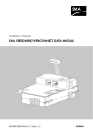
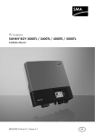
Product Description
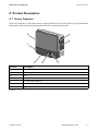
4 Product Description
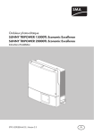
4.1 Sunny Tripower
The Sunny Tripower is a PV inverter which converts the direct current of the PV array to grid-compliant
alternating current and performs three-phase feed-in into the electricity grid.
A
G
B
F
E
Position
A
B
C
D
E
F
G
D
C
Description
Type label
Ventilation grid
LEDs
Display
DC switch-disconnector*
Lower enclosure lid
Upper enclosure lid
*optional
Installation Manual
STP20TLHE-IA-IEN122222
15
SMA Solar Technology AG
Product Description
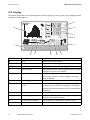
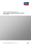
4.2 Display
The display shows the current operating data of the inverter (e.g. status, power, input voltage) as well
as faults and disturbances.
kWh
kVAr
kW
M
kVArh
kWh
MVArh
MWh
A
B
C
D
L
E
K
Position
A
B
C
D
E
F
G
H
I
K
L
16
I
H
G
F
Description
Power
Day
Total
Active functions
Explanation
Displays the current power
Displays the daily energy
Displays the total amount of energy fed in until now
The symbols indicate which communication or power
regulation functions are enabled.
Phase assignment
The phase assignment states the line conductor for
which output current or output voltage is currently
being displayed.
Electricity grid event number Event number of a disturbance in the electricity grid
Output voltage/output
The display alternately shows the output voltage and
current
the output current of the line conductor. The display
automatically switches between the 3 connected line
conductors.
Inverter event number
Event number of a device disturbance
Input voltage/input current The display alternately shows the input voltage and
the input current of the inverter.
PV array event number
Event number of a disturbance in the PV array
Text line
The text line shows event messages.
STP20TLHE-IA-IEN122222
Installation Manual
SMA Solar Technology AG
Position
M
Description
Power and yield curve
Product Description
Explanation
The diagram shows the changes in power over the
last 16 feed-in hours or the energy yields over the last
16 days. Tap the display once to switch between
views.
Symbols on the Display
Symbol
Designation
Tap symbol
Explanation
You can operate the display by tapping it:
• Single tap: the backlight switches on or the
display scrolls one message further.
Telephone receiver
Installation Manual
• Double tap: the display shows successively the
firmware version, the serial number or
designation of the inverter, the Bluetooth NetID,
the configured country data set and display
language.
Device disturbance present. Contact the SMA Service
Line.
Spanner
Signifies a disturbance that can be resolved on-site.
Bluetooth
Bluetooth communication is enabled.
Bluetooth connection
Bluetooth connection to other devices is active.
Multi-function relay
The multi-function relay is active.
Temperature symbol
The power of the inverter is limited due to excessive
temperature.
Power limitation
The external active power limitation via the
Power Reducer Box is active.
PV array
‒
Inverter
‒
STP20TLHE-IA-IEN122222
17
SMA Solar Technology AG
Product Description
Symbol
Designation
Grid relay
Electricity grid
Explanation
When the grid relay is closed, the inverter feeds into
the grid. When the grid relay is open, the inverter is
disconnected from the electricity grid.
‒
4.3 DC switch-disconnector
The DC switch-disconnector is optional. If you have ordered the inverter with DC switch-disconnector,
it will be pre-installed in the inverter on delivery.
Using the DC switch-disconnector, you can manually close or interrupt the electric circuit between the
PV array and the inverter. The DC switch-disconnector enables safe disconnection of the inverter from
the PV array. The disconnection takes place at all poles.
4.4 Communication
The inverter is equipped with a Bluetooth interface as standard. A multi-function relay and an
additional communication interface (e.g. RS485) can be retrofitted. The inverter can communicate
with special SMA communication products (e.g. data logger, software) or other inverters via the
communication interfaces (for information on supported communication products, see
www.SMA.de/en). You can only set the inverter's parameters using SMA communication products.
If you communicate via Bluetooth, you can protect the inverter with a plant password for the user and
a plant password for the installer. All inverters are delivered with the same factory-installed plant
passwords. You must change plant passwords using a communication product in order to protect the
PV plant from unauthorised access.
If you do not communicate via Bluetooth, deactivate the Bluetooth communication
(see Section 6.6.1 "Bluetooth" (page 50)). This protects your PV plant from unauthorised access.
Various parameter displays
Depending on the type of communication, RS485 or Bluetooth, the parameters and
messages are displayed differently on the communication products.
Example: parameter display for testing the fan
• If you are using RS485: parameter "CoolSys.FanTst"
• If you are using Bluetooth: parameter "Fan test"
18
STP20TLHE-IA-IEN122222
Installation Manual
SMA Solar Technology AG
Product Description
4.5 Multi-Function Relay
The inverter may be equipped with a multi-function relay. The multi-function relay is an interface for
error messages or for controlling loads. Disturbances can be transmitted to a disturbance sensor.
For this purpose, the multi-function relay switches the disturbance sensor on and off. The multi-function
relay can control a load via a contactor. For this purpose, the inverter determines when the load is
switched on and off, depending on the operating parameters and measured values. You can
configure the multi-function relay for various operating modes (see Technical Description
"Multi-Function Relay and OptiTrac Global Peak" available at www.SMA.de/en).
4.6 Feed-In Management
The Sunny Tripower is capable of utilising reactive power and can feed reactive power into the grid
via the setting of a default value for the displacement power factor (cos φ). Additionally, this inverter
is also equipped with advanced feed-in management functions, e.g. power limitation and dynamic
grid support. You can enable and configure these functions depending on the requirements set by the
network operator.
You can find detailed information on setting the parameters of these functions in the Technical
Description "Measured Values and Parameters" at www.SMA.de/en in the "Technical Description"
category for the respective inverter.
Installation Manual
STP20TLHE-IA-IEN122222
19
Product Description
SMA Solar Technology AG
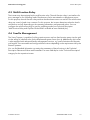
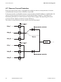
4.7 Reverse Current Protection
Every input area of the inverter is equipped with a diode as reverse current protection. A reverse
current between the input areas is therefore not possible.
If only input area A is used and the reverse current resistance of the PV modules is complied with, the
reverse current protection at input area A can be bypassed (see Section 6.7 "Activating and
Deactivating the Reverse Current Protection at Input Area A" (page 52)). Bypassing the reverse
current protection slightly increases the inverter efficiency.
The reverse current protection at input area B cannot be deactivated.
20
STP20TLHE-IA-IEN122222
Installation Manual
SMA Solar Technology AG
Mounting
5 Mounting
5.1 Safety
DANGER!
Danger to life due to fire or explosion
Despite careful construction, electrical devices can cause fires.
• Do not mount the inverter on flammable construction materials.
• Do not mount the inverter in areas where highly flammable materials are stored.
• Do not mount the inverter in a potentially explosive atmosphere.
CAUTION!
Risk of injury due to the heavy weight of the inverter (approx. 53 kg)
• Take the weight of the inverter into account for transport.
• Select a suitable mounting location and mounting surface.
• When mounting the back panel, use fastening material suitable for the mounting
surface.
• Two people are needed to mount the inverter.
CAUTION!
Risk of burns due to hot enclosure parts
• Mount the inverter in such a way that it cannot be touched inadvertently.
5.2 Selecting the Mounting Location
Consider the following requirements when selecting the mounting location:
• The mounting method and location must be suitable for the weight and size of the inverter
(see Section 13 "Technical Data" (page 85)).
• Mount on a solid surface.
• The mounting location must at all times be clear and safely accessible without the use of
additional aids such as scaffolding or lifting platforms. Non-fulfillment of these criteria may
restrict execution of service assignments.
Installation Manual
STP20TLHE-IA-IEN122222
21
SMA Solar Technology AG
Mounting
max. 15°
• Mount vertically or tilted backwards by max. 15°.
• The connection area must point downwards.
• Never mount the device with a forward tilt.
• Never mount the device with a sideways tilt.
• Do not mount horizontally.
• Mount the inverter at eye level. Given the weight of the device, this will facilitate disassembling
if service work is necessary.
• The ambient temperature should be below 40°C to ensure optimum operation.
• Do not expose the inverter to direct solar irradiation as this can cause overheating and lead to
power reduction.
• If multiple inverters are mounted in areas with high
ambient temperatures, increase the clearances
between the inverters and ensure an adequate
fresh-air supply. This prevents a reduction in inverter
power as a result of high temperatures (details on
temperature derating can be found in the Technical
Information "Temperature Derating" at
www.SMA.de/en).
22
STP20TLHE-IA-IEN122222
300
mm
50
mm
300
mm
500 mm
• Observe the recommended clearances to the walls
as well as to other inverters or other objects as
shown in the diagram. This ensures adequate heat
dissipation and sufficient room to operate the
optional DC switch-disconnector.
300 mm
• In living areas, do not mount the unit on plasterboard walls or similar in order to avoid audible
vibrations. When in operation, the inverter emits noise which may be perceived as annoying in
living areas.
Installation Manual
SMA Solar Technology AG
Mounting
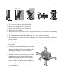
5.3 Mounting the Inverter
1. Use the back panel as a drilling template and mark the positions of the drill holes.
Display
2. Mount the back panel.
For this, use 1 upper hole on the right and on the left
and the hole in the middle.
Installation Manual
STP20TLHE-IA-IEN122222
23
SMA Solar Technology AG
Mounting
3. Hang the inverter in the back panel in such a way
that the enclosure of the inverter lies flush with the
back panel.
A
– For two people to transport the inverter, use the
recessed grips at the bottom and at the same
time hold the upper edge of the enclosure lid.
– For transport by crane, you can attach 2 ring
bolts to the top of the inverter
(see A: M10, diameter = 10 mm). To do this,
remove the filler-plugs and screw in the ring
bolts as far as they will go.
4. If necessary, remove the ring bolts after transport
and re-attach the filler-plugs.
5. Loosen all 6 captive screws of the lower enclosure
lid.
6. Lift and remove the lower enclosure lid from below.
24
STP20TLHE-IA-IEN122222
Installation Manual
SMA Solar Technology AG
Mounting
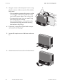
7. Screw the supplied eye bolt into the drill hole
provided in order to secure the enclosure against
removal. Only tighten the eye bolt hand-tight.
8. In order to secure the enclosure to the back panel,
fasten the underside of the enclosure with the two
M5x10 cheese-head screws supplied
(torque: 6.0 Nm).
9. Check to ensure that the inverter is securely in place.
☑ The inverter is now securely mounted to the wall.
If the inverter is not to be connected immediately, re-attach the lower enclosure lid:
– Dock the lower enclosure lid at an angle and
attach. The captive screws must protrude.
– Pre-screw all six screws and then tighten them in
the sequence shown on the right
(torque: 2.0 Nm).
Installation Manual
STP20TLHE-IA-IEN122222
25
SMA Solar Technology AG
Mounting
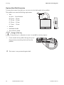
Optional Anti-Theft Protection
To protect the inverter from theft, you can secure it to the back panel with a padlock.
The padlock must meet the following requirements:
• Size:
A: 6 mm … 8 mm diameter
B: 23 mm … 29 mm
C: 23 mm … 28 mm
D: 39 mm … 50 mm
E: 13 mm … 18 mm
• Stainless
• Hardened shackle
• Secured lock cylinder
Storage of the key
Keep the key in a safe place in case it is needed for service purposes.
1. Put the shackle of the padlock through the eye of
the previously mounted eye bolt and close the
padlock.
☑ The inverter is now protected against theft.
26
STP20TLHE-IA-IEN122222
Installation Manual
SMA Solar Technology AG
Electrical Connection
6 Electrical Connection
6.1 Safety
NOTICE!
Electrostatic discharge can damage the inverter
Internal components of the inverter can be irreparably damaged by electrostatic
discharge.
• Earth yourself before touching any components.
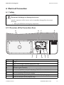
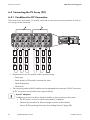
6.2 Overview of the Connection Area
B
A
D
C
L1 L2 L3 N PE
I
Object
A
B
C
D
E
F
G
H
I
H
G
F
E
Description
DC lid
Plug for connecting the optional multi-function relay
Plug for connecting the optional RS485 communication module
Terminal for grid connection
Switch for changing the display language to English (for service purposes)
Rotary switch for setting the Bluetooth NetID
Screw for releasing and raising the display
Rotary switch for setting the country data set and the display language
Slot for SD card (for service purposes only)
Installation Manual
STP20TLHE-IA-IEN122222
27
SMA Solar Technology AG
Electrical Connection
A
+
A1 A2 A3 B1
B2
B3
A1 A2 A3 B1
B2
B3
B
C
D
E
+
F
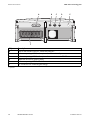
Object
A
B
C
D
E
F
Description
Jack for the handle of the DC switch-disconnector*
Enclosure opening M20 for the optional multi-function relay
Enclosure opening M32 for the optional communication via RS485
Additional enclosure opening M20
Enclosure opening M32 for the AC connection
DC connectors for connecting the strings
* optional
28
STP20TLHE-IA-IEN122222
Installation Manual
SMA Solar Technology AG
Electrical Connection
6.3 Connection to the Electricity Grid (AC)
6.3.1 Conditions for the AC Connection
You must comply with the connection requirements of your network operator.
Residual-current protective device
The inverter is equipped with an integrated all-pole-sensitive residual-current monitoring unit. The
inverter can automatically differentiate between residual currents and normal leading leakage
currents.
If the network operator stipulates a residual-current protective device, you must use a residual-current
protective device that triggers in the event of a residual-current of 100 mA or more.
Further information on the use of a residual current protective device can be found in the Technical
Information "Criteria for selecting an RCD" at www.SMA.de/en.
Cable requirements
• External diameter: 14 mm … 25 mm
• Conductor cross-section: max. 16 mm²; with bootlace ferrule: max. 10 mm².
• Stripping length: 12 mm
• The cable must be dimensioned in accordance with the local and national regulations for the
dimensioning of cables. The requirements for the minimum conductor cross-section derive from
these regulations. Examples of factors influencing cable dimensioning are: nominal AC current,
type of cable, routing method, cable bundling, ambient temperature and maximum desired line
losses (for calculation of line losses, see design software Sunny Design from software version
2.0 at www.SMA.de/en).
Connection of a second protective conductor
In some installation countries, a second protective conductor is required to prevent a touch current in
the event of a malfunction in the original protective conductor.
For installation countries falling within the scope of validity of the IEC standard 62109, the following
requirements are applicable:
• Installation of the protective conductor on the AC terminal with a conductor cross-section of at
least 10 mm² Cu.
or
• Installation of a second protective conductor on the earth terminal with the same cross-section
as the original protective conductor on the AC terminal (see Section 6.3.3 "Connecting the
Second Protective Conductor" (page 33)).
In each case, observe the applicable regulations for the site.
Installation Manual
STP20TLHE-IA-IEN122222
29
Electrical Connection
SMA Solar Technology AG
Load disconnection unit
You must install a separate, 3-phase miniature circuit-breaker for each inverter in order to ensure
that the inverter can be securely disconnected under load. The maximum permissible fuse protection
can be found in Section 13 "Technical Data" (page 85).
DANGER!
Danger to life due to fire.
When more than one inverter is connected in parallel to the same miniature circuit-breaker,
the protective function of the miniature circuit-breaker is no longer guaranteed. It can result
in a cable fire or destruction of the inverter.
• Never connect multiple inverters to the same miniature circuit-breaker.
• Observe the maximum permissible fuse protection of the inverter when selecting the
miniature circuit-breaker.
DANGER!
Danger to life due to fire.
When a generator (inverter) and a load are connected to the same miniature circuitbreaker, the protective function of the miniature circuit-breaker is no longer guaranteed.
The current from the inverter and the electricity grid can accumulate to overcurrents which
are not detected by the miniature circuit-breaker.
• Never connect loads between the inverter and the miniature circuit-breaker without
fuse protection.
• Always protect loads separately.
NOTICE!
Damage to the inverter caused by use of screw-type fuses as load-disconnect
units!
A screw-type fuse, e.g. DIAZED fuse or NEOZED fuse, is not a switch-disconnector and thus
may not be used as a load disconnection unit. A screw-type fuse only acts as cable
protection.
If the inverter is disconnected under load using a screw-type fuse, the inverter may be
damaged.
• Use only a switch-disconnector or a miniature circuit-breaker as a load disconnection
unit.
30
STP20TLHE-IA-IEN122222
Installation Manual
SMA Solar Technology AG
Electrical Connection
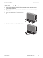
6.3.2 AC Connection Procedure
1. Check the line voltage and compare it with the permissible voltage range (see Section 13
"Technical Data" (page 85)).
2. Disconnect the miniature circuit-breaker from all three line conductors and secure against
reconnection.
3. Loosen all 6 captive screws of the lower enclosure
lid.
4. Lift and remove the lower enclosure lid from below.
Installation Manual
STP20TLHE-IA-IEN122222
31
Electrical Connection
SMA Solar Technology AG
5. Check that the country setting of the inverter is correct by using the supplementary sheet
provided with the default settings.
If the inverter is not set to the desired country data set, adjust the country data set using the rotary
switches as described in Section 6.5 "Setting the Country Data Set and Display Language"
(page 42).
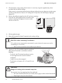
6. Remove the adhesive tape from the AC enclosure opening.
7. Insert the AC cable gland from the outside into the
enclosure opening and tighten it from the inside
with the counter nut.
8. Pull the cable through.
9. Raise all 5 terminals of the AC terminal as far as they will go.
NOTICE!
Risk of fire when connecting 2 conductors
If 2 conductors are connected to one terminal, a poor electrical contact can result in
overheating or a risk of fire.
• Never connect more than one conductor per terminal.
10. Connect L1, L2, L3, N and the protective conductor
(PE) to the AC terminal in accordance with the
labelling.
– To do this, the PE insulated conductor must be
5 mm longer than the L and N insulated
conductors.
L1 L2 L3 N PE
L1 L2
L3 N
– L and N must not be swapped.
– The direction of rotation of L1, L2 and L3 is not
relevant.
CAUTION!
Danger of crushing when terminals snap shut
The terminals close by snapping down fast and hard.
• Press the terminals down with your thumb, do not grip on either side of the terminal.
• Keep fingers away from the terminals.
32
STP20TLHE-IA-IEN122222
Installation Manual
SMA Solar Technology AG
Electrical Connection
11. Close all terminals of the AC terminal again until they snap into place.
12. Tighten the swivel nut firmly to the cable gland.
DANGER!
Danger to life due to high voltages in the inverter
• Do not switch on the miniature circuit-breaker until the PV array has been connected
and the inverter is securely closed.
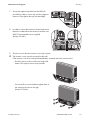
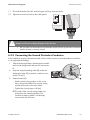
6.3.3 Connecting the Second Protective Conductor
If the installation requires, the earth terminal can be used to connect a second protective conductor
or as equipotential bonding.
1. Take the clamping bracket, cheese-head screw M6
and conical spring washer M6 out of the accessory
kit.
2. Insert the stripped earthing cable (D) under the
clamping bracket (C) (maximum conductor crosssection 16 mm²).
3. Fasten terminal (C):
– Attach conical spring washer on the screw.
Here, the grooved side of the conical spring
washer must point to the screw head.
– Tighten the screw (torque: 6.0 Nm).
☑ The teeth of the conical spring washer are
pushed into the clamping bracket. The
conductive earthing cable is conductively
connected to the enclosure.
Installation Manual
STP20TLHE-IA-IEN122222
33
Electrical Connection
SMA Solar Technology AG
6.4 Connecting the PV Array (DC)
6.4.1 Conditions for DC Connection
The inverter has 2 input areas, "A" and "B", each with its own reverse current protection. In total, up
to 6 strings can be connected.
• Requirements for the PV modules of the connected strings:
– Same type
– Same quantity of PV modules connected in series
– Identical alignment
– Identical tilt
• The connecting cables of the PV modules must be equipped with connectors. The DC connectors
for DC connection are included in the scope of delivery.
Use of Y adaptors
Y adaptors must not be visible or freely accessible in close proximity to the inverter.
• The DC electric circuit must not be interrupted by Y adaptors.
• Observe the procedure for disconnecting the inverter as described in
Section 8 "Disconnecting the Inverter from Voltage Sources" (page 58).
34
STP20TLHE-IA-IEN122222
Installation Manual
SMA Solar Technology AG
Electrical Connection
• If the inverter is not equipped with a DC switch-disconnector but this is mandatory in the country
of installation, install an external DC switch-disconnector.
• The following limit values at the DC input of the inverter must not be exceeded:
Maximum input voltage
1,000 V (DC)
Maximum input current
36 A (DC)
No mixed connections between input areas
For instance, if the positive pole of a string is connected at input area A and the negative
pole of the same string is connected at input area B, this is called a mixed connection.
Only connect strings at 1 input area and never mix the input areas A and B!
Otherwise, the inverter no longer fulfills the requirements of the EMC Directive (Directive
on the electromagnetic compatibility of a device) and forfeits its operation licence.
Installation Manual
STP20TLHE-IA-IEN122222
35
Electrical Connection
SMA Solar Technology AG
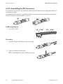
6.4.2 Assembling the DC Connectors
For connection to the inverter, all connection cables of the PV modules must be equipped with the DC
connectors provided.
To assemble the DC connectors, proceed as follows. Ensure the connectors have the correct polarity.
The DC connectors have the symbols "+" and "‒".
Cable requirements
• Use a PV1-F cable.
Procedure
1. Lead the stripped cable all the way into the plug.
2. Press the clamping bracket down.
☑ The clamping bracket snaps audibly into place.
36
STP20TLHE-IA-IEN122222
Installation Manual
SMA Solar Technology AG
Electrical Connection
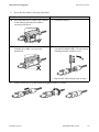
3. Ensure that the cable is correctly positioned:
Result
Measure
☑ If the stranded wire is visible in the chamber • Proceed to Step 4.
of the clamping bracket, the cable is
correctly positioned.
☑ If the stranded wire is not visible in the
chamber, the cable is not correctly
positioned.
• Loosening the clamping bracket: insert a
screwdriver (blade width: 3.5 mm) into the
clamping bracket and lever it out.
+
• Remove the cable and go back to step 1.
4. Push the swivel nut up to the thread and tighten (torque: 2.0 Nm).
Installation Manual
STP20TLHE-IA-IEN122222
37
Electrical Connection
SMA Solar Technology AG
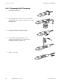
6.4.3 Opening the DC Connector
1. Unscrew the swivel nut.
2. Unlocking the DC connector: insert a screwdriver
(blade width: 3.5 mm) into the snap slot on the side
and lever it out.
3. Carefully pull the DC connector apart.
4. Loosening the clamping bracket: insert a
screwdriver (blade width: 3.5 mm) into the
clamping bracket and lever it out.
5. Remove the cable.
38
STP20TLHE-IA-IEN122222
Installation Manual
SMA Solar Technology AG
Electrical Connection
6.4.4 Connecting the PV Array (DC)
DANGER!
Danger to life due to high voltages in the inverter
• Before connecting the PV array, ensure that the AC miniature circuit-breaker is
disconnected from all 3 line conductors and that it cannot be reconnected.
NOTICE!
Destruction of the inverter due to overvoltage
If the voltage of the PV modules exceeds the maximum input voltage of the inverter, it can
be destroyed by the overvoltage. This will void all warranty claims.
• Do not connect strings to the inverter that have an open-circuit voltage greater than
the maximum input voltage of the inverter.
• Check the plant design.
NOTICE!
Excessive voltages can destroy the measuring device
• Only use measuring devices with a DC input voltage range up to at least 1,000 V.
1. Check the connection cables of the PV modules for
correct polarity and make sure that the maximum
input voltage of the inverter is not exceeded.
At an ambient temperature over 10°C, the opencircuit voltage of the PV modules should not exceed
90% of the maximum input voltage of the inverter.
If this is not the case, review the plant design and
the PV module circuitry. Otherwise, the maximum
inverter input voltage may be exceeded at low
ambient temperatures.
2. Check the strings for earth faults as described in
Section 11.1 "Checking the PV Array for Earth
Faults" (page 75).
Installation Manual
STP20TLHE-IA-IEN122222
39
SMA Solar Technology AG
Electrical Connection
3. Check the assembled DC connectors for correct
polarity and connect them to the inverter.
☑ The DC connectors click audibly into position.
To release the DC connectors, see Section 12.1
"Dismantling the Inverter" (page 81).
A1
A2
A3
B1
B2
B3
+
+
4. In order to seal the inverter, all unneeded DC inputs must be closed with DC connectors and
sealing plugs:
Sealing plugs
Do not insert the sealing plugs directly into the DC inputs on the inverter.
– For unused DC plug connectors, push down the
clamping bracket and push the swivel nut up to
the thread.
1
2
+
– Insert the sealing plug into the DC connector.
+
– Fasten the DC connector (torque: 2.0 Nm).
+
40
STP20TLHE-IA-IEN122222
Installation Manual
SMA Solar Technology AG
Electrical Connection
– Insert the DC connectors with sealing plugs into
the corresponding DC inputs on the inverter.
☑ The DC connectors click audibly into position.
A1
A2
A3
B1
B2
B3
+
5. Ensure that all DC connectors are securely in place.
☑ You can now commission the inverter as described in Section 7 "Commissioning" (page 55).
The following connections and settings are optional.
Installation Manual
STP20TLHE-IA-IEN122222
41
SMA Solar Technology AG
Electrical Connection
6.5 Setting the Country Data Set and Display Language
The inverter can be configured for various countries. This can be done prior to commissioning via
2 rotary switches on the display or after commissioning by configuring the "CntrySet" or "Set country
standard" parameter using a communication product (e.g. Sunny WebBox or Sunny Explorer).
For devices ordered without any specified country of installation, the default country setting is
"VDE-AR-N4105-HP" and the display language is set to German.
Both rotary switches are set to 0 upon delivery. If you have ordered the inverter with specific country
settings, they will have already been preset at the factory via a communication product. In this case,
you will not be able to recognise the current setting by the switch position.
If changes are made via the rotary switches or via a communication product, the default grid
parameters are overwritten. They cannot be restored, and must be re-entered via a communication
product.
The display language can be changed at any time using the rotary switches, independent of the grid
parameters. This means that the default grid parameters remain unchanged, but the display messages
are shown in the set language.
Changes will be accepted immediately after switching the miniature circuit-breaker on. If an
unprogrammed switch setting is selected, the inverter displays an error message. The last valid setting
is retained.
79
ON
1
E
2
A B
42
STP20TLHE-IA-IEN122222
Installation Manual
SMA Solar Technology AG
Electrical Connection
SMA Grid Guard-Protected Country Data Sets
In some countries, the local connection conditions demand a mechanism which prevents the
parameters for the feed-in from being changed. Therefore, certain country data sets are protected
against unauthorised changes. They can only be unlocked with a personal access code - the
SMA Grid Guard code.
SMA Grid Guard-protected country data sets are automatically blocked for 10 feed-in hours after
commissioning, or after the last alteration. If the country data set is changed after these 10 feed-in
hours, the inverter does not accept the changes and displays the error message "Grid param. locked".
If, however, a later change to the country data set only relates to a change of the display language
via the rotary switches in the inverter, this change is immediately applied.
It is also possible to configure country data sets (parameter "CntrySet" or "Set country standard"), and
to lock or unlock these manually via a communication product. To block a data set, enter the digit
sequence "54321" instead of the password into the SMA Grid Guard code field. The data set can
only be unlocked by entering a personal, 10-digit SMA Grid Guard code which is valid for a
maximum of 10 feed-in hours. The application form for the personal access code is available at
www.SMA.de/en, in the "Certificate" category of the respective inverter.
The language can be configured without a password, regardless of the country data set.
Changing parameters in SMA Grid Guard-protected country data sets
If the parameters within protected country data sets are changed, these are no longer
protected and instead of the standard, "ADJ" or "Special setting" is displayed. In this case,
a change to parameters is not locked automatically after 10 feed-in hours, but has to be
locked manually. To manually lock the parameters, set the SMA Grid Guard Code to
"54321".
Further information on parameter settings
For detailed information on making adjustments and changing parameters, see the
corresponding user manual for your communication product.
The last change (executed via rotary switch or communication product) is always verified and
activated if applicable. Consequently, the switch position may not necessarily show the actual country
configuration.
Installation Manual
STP20TLHE-IA-IEN122222
43
SMA Solar Technology AG
Electrical Connection
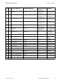
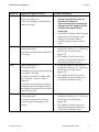
6.5.1 Checking the Country Data Set
Make sure that the inverter is set to the installation country.
Before commissioning:
• Check that the country data set of the inverter is correct by using the supplementary sheet
provided and comparing this to the default settings of the inverter.
After commissioning:
• Check that the country data set is correct using the display message during (re-)commissioning
(see Section 7 "Commissioning" (page 55)).
• Check that the country data set is correct by tapping the display twice and viewing the display
messages of the start-up phase again.
or
• Check that the country data set is correct using the "SMA grid guard" measurement channel via
an SMA communication product.
Display language
Once you have configured the country data set, you can always set the display language
later using rotary switch B. However, you have to then set rotary switch A to "0" in order to
keep the country data set.
The settings of each country data set are specified in the operating parameters. The parameters can
be read out using a communication product. The description of the operating parameters is available
at www.SMA.de/en in the category "Technical Description" of the respective inverter.
(A) (B) Country data set
Display language
0
0
Default settings
Default settings
0
1
Retained
English
0
2
Retained
German
0
3
Retained
French
0
4
Retained
Spanish
0
5
Retained
Italian
0
6
Retained
Greek
0
7
Retained
Czech
44
STP20TLHE-IA-IEN122222
SMA Grid Guard
protection
Dependent on
parameter set
Dependent on
parameter set
Dependent on
parameter set
Dependent on
parameter set
Dependent on
parameter set
Dependent on
parameter set
Dependent on
parameter set
Dependent on
parameter set
Country
Dependent on
parameter set
Dependent on
parameter set
Dependent on
parameter set
Dependent on
parameter set
Dependent on
parameter set
Dependent on
parameter set
Dependent on
parameter set
Dependent on
parameter set
Installation Manual
SMA Solar Technology AG
Electrical Connection
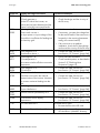
(A) (B) Country data set
Display language
0
8
Retained
Korean
0
9
Retained
Portuguese
0
A
Retained
Dutch
0
B
Retained
Slovenian
0
C
Retained
Bulgarian
0
D
Retained
Polish
1
0
VDE0126-1-1
German
SMA Grid Guard
protection
Dependent on
parameter set
Dependent on
parameter set
Dependent on
parameter set
Dependent on
parameter set
Dependent on
parameter set
Dependent on
parameter set
Yes
1
1
6
8
VDE-AR-N4105-HPa)
VDE0126-1-1
German
French
Yes
Yes
1
2
2
3
4
4
4
4
5
5
5
9
0
8
2
0
1
8
9
1
2
A
VDE 0126-1-1/UTEb)
VDE0126-1-1
AS4777.3
CEI0-21Extc)*
RD1663-A
RD1663/661-A
PPC
PPC
KEMCO 502_2009
KEMCO 502_2009
G59/2
French
Italian
English
Italian
Spanish
Spanish
Greek
English
English
Korean
English
Yes
Yes
No
Yes
Yes
Yes
No
No
No
No
No
Installation Manual
Country
Dependent on
parameter set
Dependent on
parameter set
Dependent on
parameter set
Dependent on
parameter set
Dependent on
parameter set
Dependent on
parameter set
Germany,
Switzerland
Germany
Switzerland,
France
France
Switzerland
Australia
Italy
Spain
Spain
Greece
Greece
South Korea
South Korea
England
STP20TLHE-IA-IEN122222
45
SMA Solar Technology AG
Electrical Connection
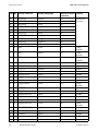
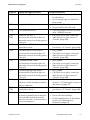
(A) (B) Country data set
Display language
6
6
6
6
6
6
6
6
6
6
7
0
1
2
3
4
5
6
7
8
9
4
EN50438
EN50438
EN50438
EN50438
EN50438
EN50438
EN50438
EN50438
EN50438
EN50438
PPDS
German
English
French
Italian
Spanish
Greek
Czech
Portuguese
Bulgarian
Polish
Czech
SMA Grid Guard
protection
Yes
Yes
Yes
Yes
Yes
Yes
Yes
Yes
Yes
Yes
Yes
7
5
PPDS
English
Yes
7
6
PPDS
German
Yes
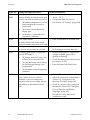
7
7
7
A
A
A
A
A
8
9
A
0
1
2
3
4
C10/11*
C10/11*
C10/11*
MVtg-Directive
MVtg-Directive
MVtg-Directive
MVtg-Directive
MVtg-Directive
French
English
German
German
English
French
Spanish
Czech
Yes
Yes
Yes
Yes
Yes
Yes
Yes
Yes
A
B
B
B
B
B
C
0
1
2
3
4
SI 4777*
MVtg-Directive int
MVtg-Directive int
MVtg-Directive int
MVtg-Directive int
MVtg-Directive int
English
German
English
French
Spanish
Czech
Yes
Yes
Yes
Yes
Yes
Yes
B
B
C
C
C
8
C
0
1
2
IEC61727/MEA
IEC61727/PEA
Customer
Customer
Customer
English
English
English
German
French
No
No
No
No
No
46
STP20TLHE-IA-IEN122222
Country
Various EU
countries
Czech
Republic
Czech
Republic
Czech
Republic
Belgium
Belgium
Belgium
Germany
Flexible
France
Spain
Czech
Republic
Israel
Germany
Flexible
France
Spain
Czech
Republic
Thailand
Thailand
Flexible
Flexible
Flexible
Installation Manual
SMA Solar Technology AG
Electrical Connection
(A) (B) Country data set
Display language
C
C
C
C
D
D
D
D
D
D
D
E
E
E
E
E
E
E
F
Spanish
Italian
Greek
Czech
English
German
French
Spanish
Italian
Greek
Czech
English
German
French
Spanish
Italian
Greek
Czech
SD-Card
3
4
5
6
0
1
2
3
4
5
6
0
1
2
3
4
5
6
0
Customer
Customer
Customer
Customer
Off-Grid60*
Off-Grid60*
Off-Grid60*
Off-Grid60*
Off-Grid60*
Off-Grid60*
Off-Grid60*
Off-Grid50*
Off-Grid50*
Off-Grid50*
Off-Grid50*
Off-Grid50*
Off-Grid50*
Off-Grid50*
SD-Card
SMA Grid Guard
protection
No
No
No
No
No
No
No
No
No
No
No
No
No
No
No
No
No
No
No
a)
Setting in accordance with VDE-AR-N-4105 for PV plants > 13.8 kVA (Germany)
b)
Special setting: Bluetooth transmission power reduced (in accordance with French standards)
c)
Setting according to CEI 0-21 for PV plants with external grid and plant protection > 6 kVA (Italy)
*
Planned
Country
Flexible
Flexible
Flexible
Flexible
Flexible
Flexible
Flexible
Flexible
Flexible
Flexible
Flexible
Flexible
Flexible
Flexible
Flexible
Flexible
Flexible
Flexible
Flexible
If the inverter is not set to the installation country, there are several ways of configuring the required
country data set:
• Setting via 2 rotary switches, as described in Section 6.5.3 "Setting the country data set and
language using rotary switches" (page 49).
• Alternatively you can conduct the settings via the "CntrySet" or "Set country standard"
parameters with a communication product, once you have commissioned the inverter.
• If you require adjusted parameter settings for your installation site, you can change these with
the help of a communication product.
Installation Manual
STP20TLHE-IA-IEN122222
47
Electrical Connection
SMA Solar Technology AG
6.5.2 Extension of the Deactivation Limits
The deactivation criteria (voltage, frequency) are specified via country parameters.
The inverters have the additional country data set "MVtgDirective/Medium-Voltage Directive
(Germany)". This parameter expands the deactivation limits of the inverter for voltage and frequency
to a maximum/minimum. This country setting may only be selected if the plant or the inverter is
operated with external three-phase decoupling protection, which will automatically disconnect the
inverter from the electricity grid if non-permissible voltage and frequency values occur.
Device protection is still guaranteed.
DANGER!
Electric shock due to missing external decoupling protection.
If you set the country data set "MVtgDirective/Medium-Voltage Directive (Germany)", you
may only operate the inverter with external 3-phase decoupling protection. Without
external three-phase decoupling protection, the inverter will not disconnect from the
electricity grid when the standard requirement is exceeded.
• Install external 3-phase decoupling protection.
48
STP20TLHE-IA-IEN122222
Installation Manual
SMA Solar Technology AG
Electrical Connection
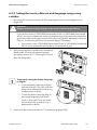
6.5.3 Setting the country data set and language using rotary
switches
1. Disconnect the inverter (see Section 8 "Disconnecting the Inverter from Voltage Sources"
(page 58)).
DANGER!
Danger to life due to high voltages in the event of electricity grid failure
If you set the inverter to "Off-Grid50/Island mode 50 Hz" or "Off-Grid60/Island mode
60 Hz", you may not operate the inverter on the electricity grid, but only on the stand-alone
grid, because the inverter does not then satisfy any country-specific standards or directives.
If there is an electricity grid failure, this prevents danger of backfeed.
• If the inverter is set to "Off-Grid50/Island mode 50 Hz" or "Off-Grid60/Island mode
60 Hz", never operate the inverter directly on the electricity grid.
2. Set the rotary switches A and B with a screwdriver
(blade width: 2.5 mm) to the desired position
(see table in Section 6.5.1 "Checking the Country
Data Set" (page 44)).
79
ON
E
Temporarily setting the display language
to English
E
ON
79
• To reset the display language back to
the original language, push the left
switch 1 down until it locks into place.
Use an object with a small tip, e.g. a
ballpoint pen to do this.
ON
79
• To set the display language to English,
push the left switch 1 up until it locks into
place. Use an object with a small tip, e.g.
a ballpoint pen to do this.
E
3. Commission the inverter (see Section 7 "Commissioning" (page 55)).
Installation Manual
STP20TLHE-IA-IEN122222
49
SMA Solar Technology AG
Electrical Connection
6.6 Communication
6.6.1 Bluetooth
Communication via Bluetooth with a communication product is activated as standard. Networking
with other inverters via Bluetooth is deactivated by default.
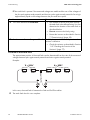
The following setting options are possible via a rotary switch.
Switch position
(NetID)
0
1
2…F
Setting
Bluetooth communication is deactivated.
Communication via Bluetooth with communication product possible, no
networking with other inverters (default settings)
Networking via Bluetooth with other inverters is activated.
If you do not communicate using Bluetooth, deactivate the Bluetooth communication on your inverter.
This protects your PV plant from unauthorised access.
In order to restrict communication via Bluetooth between the inverters of your PV plant and those of
neighbouring systems, you can assign an individual NetID to the inverters of your PV plant (switch
position 2 … F). However, this is only necessary if neighbouring plants are located within a radius of
500 m.
So that all inverters in your PV plant are detected by your communication product, all inverters must
have the same NetID.
1. Determine a free NetID using Sunny Explorer (see Sunny Explorer user manual).
2. Disconnect the inverter (see Section 8 "Disconnecting the Inverter from Voltage Sources"
(page 58)).
3. Set the arrow on the right-hand rotary switch C to
the required position using a screwdriver
(blade width: 2.5 mm).
79
ON
E
4. Commission the inverter (see Section 7 "Commissioning" (page 55)).
Acceptance of settings
The Bluetooth settings will only be accepted upon commissioning the inverter.
50
STP20TLHE-IA-IEN122222
Installation Manual
SMA Solar Technology AG
Electrical Connection
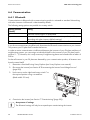
6.6.2 Multi-Function Interface
The inverter is equipped with a slot for multi-function interfaces. This slot is designed to connect a
simple multi-function relay or an SMA Power Control Module. The interface can either be retrofitted,
installed at the factory according to a specific order, or included in the regular scope of delivery.
Multi-Function Relay
You can configure the multi-function relay for various operating modes. The multi-function relay is
used, for example, to switch fault indicators on or off (for information on installation and configuration,
see installation manual of the multi-function relay).
SMA Power Control Module
The SMA Power Control Module enables the inverter to implement grid management services and is
equipped with an additional multi-function relay (for information on installation and configuration,
see installation manual of the SMA Power Control Module).
6.6.3 Communication Interface
The inverter can optionally be fitted with an extra communication interface (e.g., RS485). This
communication interface enables the inverter to communicate with special SMA communication
products or other inverters (for information on supported products, see www.SMA.de/en).
The interface can either be retrofitted, installed at the factory according to a specific order, or included
in the regular scope of delivery.
You can only set the operating parameters of the inverter via SMA communication products. You can
set the country data set of the inverter via the two rotary switches in the inverter only prior to
commissioning or within the first ten operating hours.
Display of parameters
Depending on the type of communication, RS485 or Bluetooth, the parameters and
messages are displayed differently on the communication products.
Example of how the country data set parameter is displayed:
• For communication with RS485: "CntrySet" parameter
• If you are using Bluetooth: parameter "Set country standard"
Installation Manual
STP20TLHE-IA-IEN122222
51
Electrical Connection
SMA Solar Technology AG
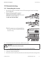
6.7 Activating and Deactivating the Reverse Current Protection at
Input Area A
The reverse current protection is activated upon delivery. If you are using both input areas, the reverse
current protection must be activated at both input areas.
If you are using only input area A, you can deactivate the reverse current protection at input area A,
which will slightly increase the inverter efficiency.
The reverse current protection at input area B cannot be deactivated.
The procedure for deactivating and reactivating the reverse current protection at input area A is
described below.
Requirements for deactivating the reverse current protection:
• Input area B must not be used.
• The reverse current resistance of the PV modules must be complied with.
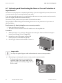
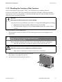
Procedure
1. When the inverter is in operation, disconnect the inverter (see Section 8 "Disconnecting the
Inverter from Voltage Sources" (page 58)).
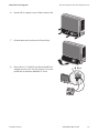
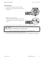
2. Loosen the screws of the upper enclosure lid.
For this purpose, use an Allen key (AF 4).
3. Pull the upper enclosure lid forwards to remove it.
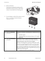
Jumper cable
Use only the supplied jumper cable to deactivate the reverse current protection.
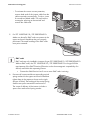
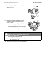
4. Deactivating or activating the reverse current protection at input area A:
– To deactivate the reverse current protection,
insert both ends of the jumper cable into the
yellow terminals as far as they will go. Do not
kink the cable.
52
STP20TLHE-IA-IEN122222
Installation Manual
SMA Solar Technology AG
Electrical Connection
– To activate the reverse current protection,
remove both ends of the jumper cable from the
yellow terminals consecutively. To do so, insert
a screwdriver (blade width: 3.5 mm) into the
rectangular opening on the terminal and
remove the cable end.
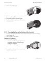
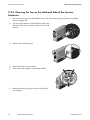
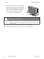
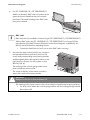
5. For STP 15000TLHE-10 / STP 20000TLHE-10:
Make sure that all 4 EMC seals are present in the
upper enclosure lid and that they are correctly
positioned. The metal braiding of the EMC seals
must point outwards.
EMC seals
EMC seals are only installed in inverters of type STP 15000TLHE-10 / STP 20000TLHE-10.
Without EMC seals, the STP 15000TLHE-10 / STP 20000TLHE-10 no longer fulfil the
requirements of the EMC Directive (Directive on the electromagnetic compatibility of a
device) and forfeit their operating licence.
• Contact the SMA Service Line if one or more EMC seals is missing.
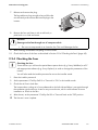
6. Pre-screw all screws and the corresponding conical
spring washers for the upper enclosure lid and then
tighten them in the sequence shown on the right
(torque: 6.0 Nm). The toothing of the conical spring
washers must point towards the enclosure lid.
The scope of delivery of the inverter includes a
spare screw and conical spring washer.
Installation Manual
STP20TLHE-IA-IEN122222
53
Electrical Connection
SMA Solar Technology AG
DANGER!
Danger to life due to live enclosure lid
The earthing of the upper enclosure lid is ensured by the toothed conical spring washers.
• For all 6 screws attach the conical spring washers with the toothing facing towards
the enclosure lid.
54
STP20TLHE-IA-IEN122222
Installation Manual
SMA Solar Technology AG
Commissioning
7 Commissioning
7.1 Commissioning the Inverter
1. The following conditions must be fulfilled before commissioning:
– Correct mounting (see Section 5)
– Correct country setting (see Section 6.5).
– AC cable correctly connected (see Section 6.3)
– DC cable correctly connected (PV strings) (see Section 6.4)
– Unused DC inputs are closed using the corresponding DC plug connectors and sealing plugs
(see Section 6.4.4)
– All enclosure openings are closed.
– The miniature circuit-breaker is of the correct size.
2. Dock the lower enclosure lid at an angle and
attach. The captive screws must protrude.
3. Pre-screw all six screws and then tighten them in the
sequence shown on the right (torque: 2.0 Nm).
For this purpose, use an Allen key (AF 3).
4. If an external DC switch-disconnector is installed, switch it off.
Installation Manual
STP20TLHE-IA-IEN122222
55
SMA Solar Technology AG
Commissioning
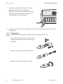
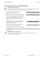
5. If the inverter is equipped with an integrated DC switch-disconnector, plug the handle in and
switch it on.
– Set the handle of the DC switch-disconnector to
position "0" so that the captive screws are visible
in the handle.
– Align the handle of the DC switch-disconnector
in such a way that the sharp side of the handle
points to the left.
– Insert the handle of the DC switch-disconnector
in the socket on the bottom of the inverter. To do
this, the switch position "0" must be visible from
the front.
– Secure the handle of the DC switchdisconnector with the 2 captive screws
(torque: 2 Nm). For this purpose, use an
Allen key (AF 3).
– Switch on the DC switch-disconnector.
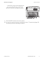
6. Switch on the miniature circuit-breaker.
☑ Green LED is lit: commissioning was successful.
or
☑ Green LED flashes if irradiation is insufficient: grid connection conditions have not yet been
reached. Wait for sufficient irradiation.
or
☑ Red LED is lit: a disturbance has occurred. Eliminate the error (see Section 11
"Troubleshooting" (page 75)).
7. If a multi-function relay is connected, switch on the supply voltage.
8. For communication via Bluetooth, make the following settings:
– Change the plant time (see the manual of the communication product).
– Change the passwords (see the manual of the communication product).
56
STP20TLHE-IA-IEN122222
Installation Manual
SMA Solar Technology AG
Commissioning
7.2 Display Messages during the Start Phase
Illustrated display messages
The display messages illustrated in this section serve as examples and, depending on the
country setting, may differ from the display messages on your inverter.
• Firstly, the firmware version of the internal
processors appears in the text line.
• After an interval of 5 seconds, or after tapping on
the enclosure lid, the serial number or designation
of the inverter and the NetID for communication via
Bluetooth will appear. The designation of the
inverter can be changed with a communication
product.
FW PACK XXXX HP XXXX
SN
2100237148
NetIDA
• After another 5 seconds, or by tapping the lid
again, the selected country data set will appear
(e.g. "VDE-AR-N4105-HP").
• After a further 5 seconds, or after a further tap,
the configured language is displayed
(example: "Sprache Deutsch" (Language German).
Sprache Deutsch
• During normal operation, the text line of the display will subsequently be clear. See Section 10
"Messages" (page 66) for possible event messages which may be displayed in the text line and
their meaning.
Showing display messages again
If you want to view the display messages of the start phase again whilst in normal
operation, double-tap the display.
Installation Manual
STP20TLHE-IA-IEN122222
57
Disconnecting the Inverter from Voltage Sources
SMA Solar Technology AG
8 Disconnecting the Inverter from Voltage Sources
DANGER!
Danger to life due to high voltages in the inverter
Death due to electric shock
The inverter operates at high voltages and must be disconnected prior to carrying out any
work on the device. In addition, if the DC connectors are pulled out without first switching
off the DC switch-disconnector, a dangerous electric arc can occur.
• Disconnect the inverter as described in this section.
CAUTION!
Risk of burns due to hot DC lid
During operation, the DC lid on the left-hand side of the connection area can become hot.
• Take care not to touch the DC lid when working in the connection area.
NOTICE!
Electrostatic discharge can damage the inverter
Internal components of the inverter can be irreparably damaged by electrostatic
discharge.
• Earth yourself before touching any components.
1. Disconnect the miniature circuit-breaker from all three line conductors and secure against
reconnection.
2. If a multi-function relay is connected, disconnect its supply voltage and ensure that the device
cannot be reconnected.
3. If an integrated or external DC switch-disconnector is connected, switch it off.
4. Wait until the LEDs, display and, if applicable, fault indicator have gone out.
5. If a DC switch-disconnector is installed, pull the
handle out. For this purpose, use an Allen key
(AF 3).
58
STP20TLHE-IA-IEN122222
Installation Manual
SMA Solar Technology AG
Disconnecting the Inverter from Voltage Sources
6. Loosen all six captive screws of the enclosure lid.
7. Lift and remove the enclosure lid from below.
8. Ensure that L1, L2 and L3 are disconnected from
voltage sources to N. For this purpose, use a test
probe with a maximum diameter of 2 mm.
Installation Manual
STP20TLHE-IA-IEN122222
59
Disconnecting the Inverter from Voltage Sources
SMA Solar Technology AG
9. Ensure that L1, L2 and L3 are disconnected from
voltage sources to PE.
10. If a multi-function relay is installed in the inverter,
ensure that it is disconnected from all voltage
sources as follows:
PE
– Release the screw of the display and flip the
display up until it clicks into place.
– Ensure that all terminals of the multi-function relay
are disconnected from voltage sources to PE.
DANGER!
Danger to life due to high voltages in the inverter
Death due to electric shock
There is residual voltage in the inverter.
• Wait 20 minutes before opening the upper enclosure lid.
• Do not open the DC lid.
☑ The inverter is now dead and work can be carried out.
60
STP20TLHE-IA-IEN122222
Installation Manual
SMA Solar Technology AG
Maintenance and Cleaning
9 Maintenance and Cleaning
9.1 Cleaning the Inverter
If the inverter is dirty, clean the enclosure lid, the display and the LEDs with clear water and a cloth
only.
9.2 Checking Heat Dissipation
If the inverter regularly reduces its power due to excessive heat (temperature symbol on the display
illuminates), this may be due to one of the following reasons:
• The ventilation grids on the sides are clogged with dirt.
Clean the ventilation grids as described in the following.
• One of the fans is clogged.
The inverter has 2 integrated fans for cooling. One of these is located at the bottom of the
inverter next to the connection area and the other on the left-hand side of the enclosure under
the ventilation grid.
If the fan enclosure is just covered in loose dust, you can clean it with a vacuum cleaner. If you
do not achieve satisfactory results with a vacuum cleaner, you can dismantle the fan for
cleaning, as described in the following sections.
9.2.1 Cleaning the Ventilation Grids
The inverter takes cooling air in from underneath on the left side and blows it out again through the
ventilation grids at the top. Clean the ventilation grids if they are dirty.
NOTICE!
Risk of damage to the inverter through intrusion of insects
• The ventilation grids must not be removed permanently, because otherwise the
device will not be protected against the intrusion of insects.
1. Turn the rotary fastener of the ventilation grid in the
direction of the arrow until the notch is in a vertical
position.
Installation Manual
STP20TLHE-IA-IEN122222
61
Maintenance and Cleaning
SMA Solar Technology AG
2. Remove the ventilation grid.
3. Clean the ventilation grid with a soft brush, a paint
brush or compressed air.
4. Re-attach the ventilation grid to the inverter.
5. Turn the notch of the rotary fastener 90° back to a
horizontal position.
9.2.2 Cleaning the Fan on the Bottom of the Inverter
1. Disconnect the inverter as described in Section 8 "Disconnecting the Inverter from Voltage
Sources" (page 58).
2. Wait for the fan to stop rotating.
Cleaning the fan guards
3. To dismantle the fan guard:
– Press both latches on the right edge of the fan
guard to the right using a screwdriver and
release from the retainer.
– Carefully remove the fan guard.
4. Clean the fan guard with a soft brush, a paint brush,
a cloth or compressed air.
62
STP20TLHE-IA-IEN122222
Installation Manual
SMA Solar Technology AG
Maintenance and Cleaning
Cleaning the fans
5. Press the latches together towards the middle.
6. Remove the fan by pulling it slowly and carefully
downwards.
7. Release and remove the plug.
The fan cables are long enough to let you lift the fan
out sufficiently to disconnect the internal plugs in the
inverter.
8. Remove the fan and clean it with a soft brush, a paint brush or a cloth and water.
NOTICE!
Damage to the fan through use of compressed air
• Do not use compressed air to clean the fan. This could damage the fan.
9. After cleaning, reassemble everything in reverse order.
10. Check the function of the fan as described in Section 9.2.4 "Checking the Fans" (page 65).
Installation Manual
STP20TLHE-IA-IEN122222
63
Maintenance and Cleaning
SMA Solar Technology AG
9.2.3 Cleaning the Fan on the Left-hand Side of the Inverter
Enclosure
1. Disconnect the inverter as described in Section 8 "Disconnecting the Inverter from Voltage
Sources" (page 58).
2. Turn the rotary fastener of the ventilation grid in the
direction of the arrow until the notch is in a vertical
position.
3. Remove the ventilation grid.
4. Wait for the fan to stop rotating.
5. Press the latches together towards the middle.
6. Remove the fan by pulling it slowly and carefully
out sideways.
64
STP20TLHE-IA-IEN122222
Installation Manual
SMA Solar Technology AG
Maintenance and Cleaning
7. Release and remove the plug.
The fan cables are long enough to let you lift the fan
out sufficiently to disconnect the internal plugs in the
inverter.
8. Remove the fan and clean it with a soft brush, a
paint brush or a cloth and water.
NOTICE!
Damage to the fan through use of compressed air
• Do not use compressed air to clean the fan. This could damage the fan.
9. After cleaning, reassemble everything in reverse order.
10. Check the function of the fans as described in Section 9.2.4 "Checking the Fans" (page 65).
9.2.4 Checking the Fans
Checking the fans
To test the fans you will need a special data capture device (e.g. Sunny WebBox) or a PC
with appropriate software (e.g. Sunny Explorer) in order to change the parameters of the
inverter.
You will also need the installer password to access the installer mode.
1. Enter the installer password.
2. Set the parameters "CoolSys.FanTst" or "Fan test" to "On" in the installer mode.
3. Check the air flow in both fans.
The inverter takes cooling air in from underneath on the left side and blows it out again through
the ventilation grids at the top. Listen for any unusual noise, which could indicate incorrect
installation or a fault in the fans.
4. After the test, set the parameter "CoolSys.FanTst" or "Fan test" back to the "Off" position.
☑ The fan test is now complete.
Installation Manual
STP20TLHE-IA-IEN122222
65
SMA Solar Technology AG
Messages
10 Messages
No display messages if no DC voltage present
Measurements and the display of messages are only possible when there is sufficient
DC voltage (green LED flashes or glows).
10.1 LED Signals
Position of the LEDs
kWh
kVAr
kW
kVArh
kWh
MVArh
MWh
A
B
C
Position
A
Description
Green LED
Status
glowing
flashing
B
C
Red LED
Blue LED
glowing
glowing
flashing
66
STP20TLHE-IA-IEN122222
Explanation
Operation
Grid connection conditions are not yet
met.
Error
Bluetooth communication is activated.
The inverter has been identified via
Sunny Explorer by setting the
"Find device" parameter.
Installation Manual
SMA Solar Technology AG
Messages
10.2 Event Messages
During an update, the relevant display message is shown in the text line of the display.
Message
< Inst. code valid >
Description
The SMA Grid Guard code entered is valid.
The configured country data set is now unlocked and can
be changed.
< No new update on the SD card >
< Grid parameter unchanged >
< Parameters set successfully >
< Reading SD Card >
< Set parameter >
< Update completed >
< Update Bluetooth >
< Update display >
< Update main CPU >
< Update communication >
< Update RS485I module >
< Update language table >
< Update file OK >
Installation Manual
If the configured country data set is protected, the
unlocking is valid for a maximum of 10 feed-in hours.
There is no update file relevant for this inverter on the
SD card or the available update has already been carried
out.
The selected switch setting is not programmed or there is
no country data set available on the
SD card.
All parameters of the SD card, e.g. country data set, have
been successfully adopted.
The inverter is currently reading the SD card.
The inverter sets the parameters of the SD card.
The inverter has successfully completed the update.
The inverter is updating the Bluetooth component.
The inverter is updating the display.
The inverter is updating the inverter component.
The inverter is updating the communication component.
The inverter is updating the RS485 communication
interface.
The inverter is updating the language table.
The update file found is valid.
STP20TLHE-IA-IEN122222
67
SMA Solar Technology AG
Messages
10.3 Error Messages
The text line on the display shows the relevant display messages whenever an error occurs. The event
numbers for the displayed error messages will appear in the text line. By tapping on the enclosure lid,
you can scroll through multi-line messages.
If the error exists over a long period of time, the red LED lights up and the multi-function relay is
activated.
In addition, depending on the severity of the disturbance
the "spanner" or "telephone receiver" symbol on the
display will light up.
• Spanner: signifies a disturbance which can be
remedied on-site (see table below).
• Telephone receiver: signifies device failure.
Contact the SMA Service Line.
Event no. Display message and cause
101 …
< Grid fault >
103
The line voltage has exceeded the
permissible range. This error can have
the following causes:
202 …
203
Corrective measures
• Check the line voltage and grid
connection on the inverter.
If the line voltage is outside the permissible
range due to local grid conditions, ask your
• The line voltage at the termination network operator if the voltage can be
adjusted at the feed-in point or if it would be
point of the inverter is too high.
acceptable to change the monitored
• The grid impedance at the
operating limits.
termination point of the inverter is
If the line voltage is within the tolerance
too high.
range, yet this error is still displayed, contact
The inverter disconnects from the
the SMA Service Line.
electricity grid for safety reasons.
• Check the triggering of the miniature
< Grid fault >
circuit-breaker.
The line voltage has fallen below the
permissible range. This error can have
the following causes:
• Check the line voltage and grid
connection on the inverter.
If the line voltage is outside the permissible
range due to local grid conditions, ask your
• AC cable damaged
network operator if the voltage can be
• The line voltage at the termination
adjusted at the feed-in point or if it would be
point of the inverter is too low.
acceptable to change the monitored
The inverter disconnects from the
operating limits.
electricity grid for safety reasons.
If the line voltage is within the tolerance
range, yet this error is still displayed, contact
the SMA Service Line.
• Electricity grid disconnected
68
STP20TLHE-IA-IEN122222
Installation Manual
SMA Solar Technology AG
Messages
Event no. Display message and cause
301
< Grid fault >
401 …
404
Corrective measures
• Check the line voltage at the
termination point of the inverter:
The 10-minute average line voltage is no
If, due to local grid conditions, the line
longer within the permissible range.
voltage exceeds the configured limiting
This can be caused by one of the
value, ask the network operator whether the
following:
voltage can be adjusted at the feed-in point,
• The line voltage at the termination
or whether it would be acceptable to modify
point of the inverter is too high.
the limiting value for power quality
• The grid impedance at the
monitoring.
termination point of the inverter is
If the line voltage is continually within the
too high.
tolerance range, and this error is still
The inverter disconnects from the grid to displayed, contact the SMA Service Line.
maintain power quality.
< Grid fault >
• Check the grid connection for strong,
short-term frequency variations.
The inverter is no longer in grid-parallel
501
operation and has stopped feed-in for
safety reasons.
< Grid fault >
The power frequency is not within the
permissible range. The inverter
disconnects from the electricity grid for
safety reasons.
601
< Grid fault >
The internal monitoring function of the
inverter has detected an excessively high
proportion of direct current in the line
current.
701
< Frequency not permitted >
< Check parameter >
The power frequency is outside the
permissible range. The inverter
disconnects from the electricity grid for
safety reasons.
• If possible, check the power frequency
and observe how often major
deviations occur.
If there are frequent fluctuations and this error
occurs as a result, ask your network operator
if it would be acceptable to change the
operating parameters.
Discuss the proposed parameters with the
SMA Service Line.
• Check the grid connection for direct
current.
• If this event occurs often, check with the
network operator whether it is possible
to raise the limiting value for
monitoring.
• As far as possible, check the power
frequency and observe how often
major fluctuations occur.
If there are frequent fluctuations and this error
occurs as a result, ask your network operator
if it would be acceptable to change the
operating parameters.
Discuss the proposed parameters with the
SMA Service Line.
Installation Manual
STP20TLHE-IA-IEN122222
69
SMA Solar Technology AG
Messages
Event no. Display message and cause
1302
< Waiting for grid voltage > or
< Installation failure grid connection >
< Check grid and fuses >
The inverter has detected an error in the
AC cabling and cannot connect to the
electricity grid. The reason for this could
be an incorrect country setting.
1501
< Reconnection fault grid >
Corrective measures
• Check AC installation
• Adjust the connection as described in
Section 6.3 "Connection to the
Electricity Grid (AC)" (page 29).
• Check that the country setting is correct:
– Via the rotary switch: see Section
6.5.1 "Checking the Country Data
Set" (page 44).
– Via communication: setting the
parameter "CntrySet" or "Set
country standard"
• Check that the country setting is correct:
The measured voltage or frequency is
too high or too low for connection to the
electricity grid.
– Via the rotary switch: see Section
6.5.1 "Checking the Country Data
Set" (page 44).
Possibly, a changed country data set or
changed parameters do not correspond
to the local requirements for connecting
to the electricity grid.
– Via communication: setting the
parameter "CntrySet" or "Set
country standard"
3301 …
3303
< Unstable operation >
70
STP20TLHE-IA-IEN122222
There is not enough power at the DC
input of the inverter for stable operation.
This may be caused by snow on the PV
modules.
• Check whether the voltage and
frequency of the electricity grid are
within the limits of the configured
country data set.
• If individual parameters within a
country data set have been changed,
re-select the original country data set
for the installation country.
• Wait for more irradiation.
• If this event recurs at medium
irradiation, check the PV plant design
and correct the circuitry of the PV array.
Installation Manual
SMA Solar Technology AG
Event no. Display message and cause
3401
< DC overvoltage >
< Disconnect generator >
The DC input voltage connected to the
inverter is too high.
3501
< Insulation resist. >
< Check generator >
The inverter has detected an earth fault in
the PV array.
3601
3701
Messages
Corrective measures
• Immediately disconnect the
inverter from the PV array, as
described in Section 8
"Disconnecting the Inverter from
Voltage Sources" (page 58). The
inverter may otherwise be
destroyed.
• Check the DC voltage of the strings for
adherence to the maximum input
voltage of the inverter before
reconnecting the inverter to the PV
array.
• Check the strings for earth faults as
described in Section 11.1 "Checking
the PV Array for Earth Faults"
(page 75).
The leakage current from the inverter and
the PV array is too high.
• The installer of the PV array must
remedy the earth faults before you
re-connect the affected string.
• Check the strings for earth faults as
described in Section 11.1 "Checking
the PV Array for Earth Faults"
(page 75).
This can be caused by a sudden earth
fault, a residual current or a device
malfunction.
• The installer of the PV array must
remedy the earth faults before you
re-connect the affected string.
< High discharge curr. >
< Check generator >
The inverter interrupts feed-in operation
immediately after exceeding a limiting
value and then automatically re-connects
to the electricity grid.
< Resid.curr.too.high >
< Check generator >
The inverter has detected a residual
current through brief earthing of the
PV array.
Installation Manual
• Check the strings for earth faults as
described in Section 11.1 "Checking
the PV Array for Earth Faults"
(page 75).
• The installer of the PV array must
remedy the earth faults before you
re-connect the affected string.
STP20TLHE-IA-IEN122222
71
SMA Solar Technology AG
Messages
Event no. Display message and cause
3801
< DC overcurrent >
< Check generator >
3901 …
3902
On the DC side of the inverter, an
overcurrent has been detected and the
inverter has briefly interrupted feed-in.
< Waiting for DC start conditions >
< Start cond. not met >
The input power or input voltage of the
PV modules is insufficient for feeding into
the electricity grid.
6001 …
6438
6501 …
6511
6603 …
6604
6701 …
6702
6801 …
6802
7001 …
7002
7008
< Self diagnosis > or
< Interference device >
< Self diagnosis > or
< Overtemperature >
Corrective measures
If this event occurs frequently:
• Check the design and the circuitry of
the PV array.
• Wait for more irradiation.
• If necessary, increase the voltage limit
for the start of feed-in if the event occurs
frequently in the morning (parameter
setting via communication).
• If this event recurs at medium
irradiation, check the PV plant design
and correct the circuitry of the PV array.
• Contact the SMA Service Line
(see Section 15 "Contact" (page 94)).
• Ensure sufficient ventilation.
• Check heat dissipation, as described in
The inverter switches off due to excessive
Section 9.2 "Checking Heat
temperature.
Dissipation" (page 61).
< Self diagnosis > or
• Contact the SMA Service Line
< Overload >
(see Section 15 "Contact" (page 94)).
< Comm. disturbed >
If this event occurs frequently:
A fault has occurred in the internal
communication of the inverter. However,
the inverter continues feeding into the
grid.
< Self diagnosis > or
< Input A defective >
< Sensor fault fan permanently on >
7101
< Disturbance sensor display
temperature >
< SD card defective >
7102
< Parameter file not found or defective >
72
STP20TLHE-IA-IEN122222
• Contact the SMA Service Line
(see Section 15 "Contact" (page 94)).
• Contact the SMA Service Line
• (see Section 15 "Contact" (page 94)).
• Contact the SMA Service Line
(see Section 15 "Contact" (page 94)).
• Contact the SMA Service Line
(see Section 15 "Contact" (page 94)).
Re-format the SD card.
• Re-save the files to the SD card.
• Copy the parameter file into the
SD card drive :\PARASET directory.
Installation Manual
SMA Solar Technology AG
Event no. Display message and cause
7105
< Param. setting failed >
7106
< Update file defect. >
7110
< No update file found >
7201 …
7202
< Data stor. not poss. >
Messages
Corrective measures
• Check the parameters of the SD card
for valid values.
• Ensure change rights via SMA Grid
Guard code.
• Re-format the SD card.
• Re-save the files to the SD card.
• Copy the update file into the SD card
drive :\UPDATE directory.
• If this fault occurs often, contact the
SMA Service Line (see Section 15
"Contact" (page 94)).
7303
An internal device fault that does not
prevent the inverter from feeding power
to the grid.
< Update main CPU failed >
7305
Internal device fault.
< Update RS485I module failed >
7307
An internal device fault that does not
prevent the inverter from feeding power
to the grid.
< Update Bluetooth failed >
• If this fault occurs again, contact the
SMA Service Line (see Section 15
"Contact" (page 94)).
• Re-try update.
7311
An internal device fault that does not
prevent the inverter from feeding power
to the grid.
< Update language table failed >
• If this fault occurs again, contact the
SMA Service Line (see Section 15
"Contact" (page 94)).
• Re-try update.
7401
An internal device fault that does not
prevent the inverter from feeding power
to the grid.
< Varistor defective >
7702 …
7703
8001
At least one of the thermally monitored
varistors is defective.
< Self diagnosis > or
< Interference device >
< Derating occurred >
• If this fault occurs again, contact the
SMA Service Line (see Section 15
"Contact" (page 94)).
• Check the varistors as described in
Section 11.2 "Checking the Function of
the Varistors" (page 77).
The power supplied by the inverter has
been reduced to below the nominal
power for more than 10 minutes due to
excessive temperature.
Installation Manual
• Contact the SMA Service Line
(see Section 15 "Contact" (page 94)).
• Re-try update.
• Contact the SMA Service Line
(see Section 15 "Contact" (page 94)).
If this event occurs frequently:
• Ensure sufficient ventilation.
• Check heat dissipation, as described in
Section 9.2 "Checking Heat
Dissipation" (page 61).
STP20TLHE-IA-IEN122222
73
SMA Solar Technology AG
Messages
Event no. Display message and cause
Corrective measures
8801 …
The display is blank. The inverter
• Wait until the temperature has risen
8803
continues feeding into the electricity grid.
above ‒25°C.
This error can have the following causes: • Contact the SMA Service Line
• The ambient temperature is so low
(see Section 15 "Contact" (page 94)).
that the display disconnects to
protect itself.
• The inverter cannot identify the
display type.
9002
• No display is connected or the
connection is defective.
< Inst. code invalid >
9003
The SMA Grid Guard code entered
(personal installer password) is not valid.
< Grid param. locked >
9005
The current country data set is locked.
< Changing grid param. not possible >
< Ensure DC supply >
• DC voltage at the DC input is not
sufficient to run the main CPU.
• The selected rotary switch setting
for the language settings is not
programmed.
9007
• The parameters to be changed are
protected.
< Abort self-test >
There is either an error in the AC
installation or the set voltage and
frequency limits do not comply with the
requirements of the Italian electricity
grids.
• Enter a valid SMA Grid Guard code.
• Enter a valid SMA Grid Guard code
for changing the country data set.
• Make sure that there is sufficient DC
voltage available (green LED is
glowing or flashing).
• Check the setting of the rotary switches
(see Section 5.4.2).
• Enter the SMA Grid Guard code.
• Check AC installation.
• Adjust the connection as described in
Section 6.3 "Connection to the
Electricity Grid (AC)" (page 29).
• Check for correct country settings as
described in Section 6.5 "Setting the
Country Data Set and Display
Language" (page 42).
The self-test is only required for
installations in Italy.
74
STP20TLHE-IA-IEN122222
Installation Manual
SMA Solar Technology AG
Troubleshooting
11 Troubleshooting
11.1 Checking the PV Array for Earth Faults
If the inverter displays event numbers "3501", "3601" or "3701", there is a high probability of an
earth fault in the PV array.
Check the strings for earth faults as described below:
1. Disconnect the inverter as described in Section 8 "Disconnecting the Inverter from Voltage
Sources" (page 58).
DANGER!
Danger to life due to live PV array.
• Only touch the cables of the PV array by their insulation.
• Do not connect strings with earth faults to the inverter.
NOTICE!
Excessive voltages can destroy the measuring device
• Only use measuring devices with a DC input voltage range up to at least 1,000 V.
2. Measure the voltages between the plus pole of
each string and the earth potential (PE).
3. Measure the voltages between the minus pole of
each string and the earth potential (PE).
4. Measure the voltages between the plus and minus
poles of each string.
Installation Manual
STP20TLHE-IA-IEN122222
75
SMA Solar Technology AG
Troubleshooting
☑ An earth fault is present if the measured voltages are stable and the sum of the voltages of
the plus pole against earth potential and the minus pole against earth potential of a string is
approximately equal to the voltage between the plus and minus poles.
Result
☑ You have detected an earth fault.
Measure
• The installer of the PV array must remedy
the earth fault in the affected string. You can
determine the location of the earth fault as
described below.
• Do not reconnect the faulty string.
• Restart the inverter as described in Section
7 "Commissioning" (page 55).
☑ You have not detected any earth fault. It is likely that one of the thermally monitored
varistors is defective.
• Check the varistors as described in Section
11.2 "Checking the Function of the
Varistors" (page 77).
Location of the earth fault
The approximate position of the earth fault can be determined from the ratio of the measured
voltages between plus against earth potential and minus against earth potential.
Example:
In this case, the earth fault is between the 2nd and 3rd PV modules.
☑ The earth fault check is now complete.
76
STP20TLHE-IA-IEN122222
Installation Manual
SMA Solar Technology AG
Troubleshooting
11.2 Checking the Function of the Varistors
If the inverter displays event number "7401", one of the varistors is probably defective.
Varistors are wear parts. Their functional efficiency diminishes with age or following repeated
responses as a result of overvoltages. It is therefore possible that one of the thermally monitored
varistors has lost its protective function.
NOTICE!
Destruction of the inverter due to overvoltage
If varistors are missing or defective, the inverter is no longer protected against overvoltages.
• Replacement varistors should be obtained as soon as possible.
• In PV plants with a high risk of overvoltages, never operate the inverter without
varistors
Check the varistors as described below:
1. Disconnect the inverter (see Section 8 "Disconnecting the Inverter from Voltage Sources"
(page 58)).
DANGER!
Danger to life due to high voltages in the inverter
Death due to electric shock
There is residual voltage in the inverter. The inverter takes 20 minutes to discharge.
• Wait 20 minutes before you open the upper enclosure lid or the DC lid.
CAUTION!
Risk of burns due to hot components inside the inverter
• Wait until the components inside the inverter have cooled down.
2. Loosen the screws of the upper enclosure lid. For
this purpose, use an Allen key (AF 4).
3. Pull the enclosure lid forwards to remove it.
Installation Manual
STP20TLHE-IA-IEN122222
77
SMA Solar Technology AG
Troubleshooting
4. Remove all varistors.
If you have not received an insertion tool for
operating the terminals with your replacement
varistors, contact SMA Solar Technology AG.
xx
xx
x
xx
x
5. Use a multimeter to check all the varistors to see if
there is a conductive connection between
connectors 2 and 3.
Result
☑ There is a conductive
connection.
Measure
The varistor is functional. Presumably there is a different error in the
inverter.
• Proceed to step 8.
☑ There is no conductive
connection.
• Contact the SMA Service Line (see Section 15 "Contact"
(page 94)).
The respective varistor is defective and must be replaced.
Varistor failure is due to influences which affect all varistors
similarly (temperature, age, induced overvoltages).
SMA Solar Technology AG recommends replacing all varistors.
The varistors are specially manufactured for use in the inverter and
are not commercially available. You must order replacement
varistors directly from SMA Solar Technology AG (see Section 14
"Accessories" (page 93)). Only use original varistors that are sold
by SMA Solar Technology AG.
• To replace the varistors, proceed to step 6.
78
STP20TLHE-IA-IEN122222
Installation Manual
SMA Solar Technology AG
6. Insert an insertion tool into the openings of the
terminal contacts.
7. Insert new varistors into the slots (as shown in the
drawing at right).
Troubleshooting
xx
xx
x
xx
x
Here, the labelling must point to the front,
i.e. towards the insertion tool.
8. For STP 15000TLHE-10 / STP 20000TLHE-10:
Make sure that all 4 EMC seals are present in the
upper enclosure lid and that they are correctly
positioned. The metal braiding of the EMC seals
must point outwards.
EMC seals
EMC seals are only installed in inverters of type STP 15000TLHE-10 / STP 20000TLHE-10.
Without EMC seals, the STP 15000TLHE-10 / STP 20000TLHE-10 no longer fulfil the
requirements of the EMC Directive (Directive on the electromagnetic compatibility of a
device) and forfeit their operating licence.
• Contact the SMA Service Line if one or more EMC seals is missing.
Installation Manual
STP20TLHE-IA-IEN122222
79
SMA Solar Technology AG
Troubleshooting
9. Pre-screw all screws and the corresponding conical
spring washers for the upper enclosure lid and then
tighten them in the sequence shown on the right
(torque: 6.0 Nm). The toothing of the conical spring
washers must point towards the enclosure lid.
The scope of delivery of the inverter includes a
spare screw and conical spring washer.
DANGER!
Danger to life due to live enclosure lid
The earthing of the upper enclosure lid is ensured by the toothed conical spring washers.
• For all 6 screws attach the conical spring washers with the toothing facing towards
the enclosure lid.
10. Restart the inverter as described in Section 7 "Commissioning" (page 55).
☑ The varistors have now been replaced and the inverter is back in operation.
80
STP20TLHE-IA-IEN122222
Installation Manual
SMA Solar Technology AG
Decommissioning
12 Decommissioning
12.1 Dismantling the Inverter
1. Disconnect the inverter as described in Section 8 "Disconnecting the Inverter from Voltage
Sources" (page 58).
2. Release and disconnect all DC connectors.
To do this, insert a flat-blade screwdriver
(blade width: 3.5 mm) into one of the side slots and
pull the DC connectors straight out.
Do NOT PULL ON THE CABLE.
☑ All DC connectors are now disconnected from
the inverter. The inverter is entirely disconnected
from the PV array.
+
A1
A2
A3
B1
B2
B3
+
3. If connected, remove all communication cables from the inverter.
CAUTION!
Risk of burns due to hot enclosure parts
• Wait 30 minutes for the enclosure to cool down before disassembling.
4. Screw off all projecting cable glands.
5. If necessary, open the anti-theft lock.
6. Remove the inverter from the back panel and remove the back panel from the mounting surface.
Installation Manual
STP20TLHE-IA-IEN122222
81
Decommissioning
SMA Solar Technology AG
12.2 Replacing the Enclosure Lid
In the event of a fault, your inverter may need to be replaced. If this is the case, you will receive a
replacement device fitted with transport lids.
DANGER!
Danger to life due to electric shock.
During operation, there are high voltages in the inverter.
• Do not operate the inverter without the upper and lower enclosure lid during
operation.
Remove jumper cable
If you have deactivated the reverse current protection at input area A by means of the
jumper cable, you must remove the jumper cable before sending the inverter back to
SMA Solar Technology AG.
Prior to returning your inverter to SMA Solar Technology AG, you must replace the upper and lower
enclosure lids of your inverter with the corresponding transport lids:
DANGER!
Danger to life due to high voltages in the inverter
Death due to electric shock
After disconnecting the inverter, there is residual voltage in the inverter. The inverter takes
20 minutes to discharge.
• Wait 20 minutes before you open the upper enclosure lid or the DC lid.
1. Disassemble the inverter as described in Section 12.1 "Dismantling the Inverter" (page 81).
2. Loosen the screws of the upper enclosure lid. For
this purpose, use an Allen key (AF 4).
3. Pull the upper enclosure lid forwards to remove it.
4. Remove the two transport lids from the replacement
device in the same manner.
5. If in place, remove the jumper cable for
deactivating the reverse current protection and
install it in the replacement device (see 6.7
"Activating and Deactivating the Reverse Current
Protection at Input Area A" (page 52)).
82
STP20TLHE-IA-IEN122222
Installation Manual
SMA Solar Technology AG
Decommissioning
6. For STP 15000TLHE-10 / STP 20000TLHE-10:
Make sure that all 4 EMC seals are present in the
upper enclosure lid and that they are correctly
positioned. The metal braiding of the EMC seals
must point outwards.
EMC seals
EMC seals are only installed in inverters of type STP 15000TLHE-10 / STP 20000TLHE-10.
Without EMC seals, the STP 15000TLHE-10 / STP 20000TLHE-10 no longer fulfil the
requirements of the EMC Directive (Directive on the electromagnetic compatibility of a
device) and will forfeit their operating licence.
• Contact the SMA Service Line if one or more EMC seals is missing.
7. Pre-screw the upper enclosure lid of your inverter to
the replacement device with the 6 enclosure lid
screws and corresponding conical spring washers
and then tighten them in the sequence shown on the
right (torque: 6.0 Nm). For this purpose, use an
Allen key (AF 4).
The toothing of the conical spring washers must
point towards the enclosure lid.
The scope of delivery of the inverter includes a
spare screw and conical spring washer.
DANGER!
Danger to life due to live enclosure lid
The earthing of the upper enclosure lid is ensured by the toothed conical spring washers.
• For all 6 screws attach the conical spring washers with the toothing facing towards
the enclosure lid.
Installation Manual
STP20TLHE-IA-IEN122222
83
Decommissioning
SMA Solar Technology AG
8. Screw the lower enclosure lid of your inverter onto the replacement device.
9. Now attach the two transport lids of the replacement device to your inverter in the same manner.
☑ Your inverter is now ready to be sent back to SMA Solar Technology AG.
10. Mount and connect the replacement device (see Section 5.3 "Mounting the Inverter" (page 23)
and Section 6 "Electrical Connection" (page 27)).
12.3 Packing the Inverter
• If the original packaging is available, the inverter should be packed in its original packaging
and be secured with tension straps.
• If the original packaging is not available, use a cardboard box suitable for the weight and size
of the inverter.
12.4 Storing the Inverter
Store the inverter in a dry place where ambient temperatures are always between
‒25°C and +60°C.
12.5 Disposing of the inverter
Dispose of the inverter at the end of its service life in accordance with the current locally applicable
disposal regulations for electronic waste. Alternatively, send it back to SMA Solar Technology AG
with shipping paid by sender, and labelled "ZUR ENTSORGUNG" ("FOR DISPOSAL")
(contact see Page 94).
84
STP20TLHE-IA-IEN122222
Installation Manual
SMA Solar Technology AG
Technical Data
13 Technical Data
13.1 DC/AC
13.1.1 SUNNY TRIPOWER 15000TL Economic Excellence
DC Input
Maximum DC power at cos φ = 1
Maximum input voltage*
MPP voltage range at 230 V AC
Rated input voltage
Minimum input voltage at 230 V AC
Start input voltage
Maximum input current
Maximum input current per string
Number of independent MPP inputs
Strings per MPP input
15,260 W
1,000 V
580 V … 800 V
580 V
570 V
620 V
36 A
36 A
1
6
* The maximum open-circuit voltage which can occur at a cell temperature of − 10°C must not exceed the maximum input voltage.
AC Output
Rated power at 230 V, 50 Hz
Maximum apparent AC power
Rated grid voltage
AC voltage range*
Nominal AC current at 230 V
Maximum output current
Maximum short-circuit current
Total harmonic factor of the output current with
total harmonic factor of the AC voltage < 2%,
AC power > 0.5 rated power
Maximum residual output current
Rated power frequency
AC power frequency*
Operating range at AC power frequency 50 Hz
Operating range at AC power frequency 60 Hz
Displacement power factor, adjustable
Feed-in phases
Connection phases
Installation Manual
15,000 W
15,000 VA
3/N/PE, 230 V/400 V
160 V … 280 V
21.7 A
24.0 A
50 A
≤ 2.6%
96 mA
50 Hz
50 Hz/60 Hz
44 Hz … 55 Hz
54 Hz … 65 Hz
0.8 overexcited … 0.8 underexcited
3
3
STP20TLHE-IA-IEN122222
85
SMA Solar Technology AG
Technical Data
Overvoltage category as per IEC 60664-1
III
* Depending on country setting
Efficiency
Maximum efficiency, ηmax
European weighted efficiency, ηEU
98.5%
98.3%
13.1.2 Sunny Tripower 15000TL High Efficiency
DC Input
Maximum DC power at cos φ = 1
Maximum input voltage*
MPP voltage range at 230 V AC
Rated input voltage
Minimum input voltage at 230 V AC
Start input voltage
Maximum input current
Maximum input current per string
Number of independent MPP inputs
Strings per MPP input
15,200 W
1,000 V
580 V … 800 V
580 V
570 V
620 V
36 A
36 A
1
6
* The maximum open-circuit voltage which can occur at a cell temperature of − 10°C must not exceed the maximum input voltage.
AC Output
Rated power at 230 V, 50 Hz
Maximum apparent AC power
Rated grid voltage
AC voltage range*
Nominal AC current at 230 V
Maximum output current
Maximum short-circuit current
Total harmonic factor of the output current with
total harmonic factor of the AC voltage < 2%,
AC power > 0.5 rated power
Maximum residual output current
Rated power frequency
AC power frequency*
Operating range at AC power frequency 50 Hz
Operating range at AC power frequency 60 Hz
86
STP20TLHE-IA-IEN122222
15,000 W
15,000 VA
3/N/PE, 230 V/400 V
160 V … 280 V
21.7 A
24.0 A
50 A
≤ 2.6%
96 mA
50 Hz
50 Hz/60 Hz
44 Hz … 55 Hz
54 Hz … 65 Hz
Installation Manual
SMA Solar Technology AG
Displacement power factor, adjustable
Feed-in phases
Connection phases
Overvoltage category as per IEC 60664-1
Technical Data
0.8 overexcited … 0.8 underexcited
3
3
III
* Depending on country setting
Efficiency
Maximum efficiency, ηmax
European weighted efficiency, ηEU
99.0%
98.7%
13.1.3 Sunny Tripower 20000TL Economic Excellence
DC Input
Maximum DC power at cos φ = 1
Maximum input voltage*
MPP voltage range at 230 V AC
Rated input voltage
Minimum input voltage at 230 V AC
Start input voltage
Maximum input current
Maximum input current per string
Number of independent MPP inputs
Strings per MPP input
20,450 W
1,000 V
580 V … 800 V
580 V
570 V
620 V
36 A
36 A
1
6
* The maximum open-circuit voltage which can occur at a cell temperature of − 10°C must not exceed the maximum input voltage.
AC Output
Rated power at 230 V, 50 Hz
Maximum apparent AC power
Rated grid voltage
AC voltage range*
Nominal AC current at 230 V
Maximum output current
Maximum short-circuit current
Total harmonic factor of the output current with
total harmonic factor of the AC voltage < 2%,
AC power > 0.5 rated power
Maximum residual output current
Rated power frequency
AC power frequency*
Installation Manual
20,000 W
20,000 VA
3/N/PE, 230 V/400 V
160 V … 280 V
29 A
29 A
50 A
≤ 2.6%
96 mA
50 Hz
50 Hz/60 Hz
STP20TLHE-IA-IEN122222
87
SMA Solar Technology AG
Technical Data
Operating range at AC power frequency 50 Hz
Operating range at AC power frequency 60 Hz
Displacement power factor, adjustable
Feed-in phases
Connection phases
Overvoltage category as per IEC 60664-1
44 Hz … 55 Hz
54 Hz … 65 Hz
0.8 overexcited … 0.8 underexcited
3
3
III
* Depending on country setting
Efficiency
Maximum efficiency, ηmax
European weighted efficiency, ηEU
98.5%
98.2%
13.1.4 Sunny Tripower 20000TL High Efficiency
DC Input
Maximum DC power at cos φ = 1
Maximum input voltage*
MPP voltage range at 230 V AC
Rated input voltage
Minimum input voltage at 230 V AC
Start input voltage
Maximum input current
Maximum input current per string
Number of independent MPP inputs
Strings per MPP input
20,300 W
1,000 V
580 V … 800 V
580 V
570 V
620 V
36 A
36 A
1
6
* The maximum open-circuit voltage which can occur at a cell temperature of − 10°C must not exceed the maximum input voltage.
AC Output
Rated power at 230 V, 50 Hz
Maximum apparent AC power
Rated grid voltage
AC voltage range*
Nominal AC current at 230 V
Maximum output current
Maximum short-circuit current
Total harmonic factor of the output current with
total harmonic factor of the AC voltage < 2%,
AC power > 0.5 rated power
Maximum residual output current
88
STP20TLHE-IA-IEN122222
20,000 W
20,000 VA
3/N/PE, 230 V/400 V
160 V … 280 V
29 A
29 A
50 A
≤ 2.6%
96 mA
Installation Manual
SMA Solar Technology AG
Rated power frequency
AC power frequency*
Operating range at AC power frequency 50 Hz
Operating range at AC power frequency 60 Hz
Displacement power factor, adjustable
Feed-in phases
Connection phases
Overvoltage category as per IEC 60664-1
Technical Data
50 Hz
50 Hz/60 Hz
44 Hz … 55 Hz
54 Hz … 65 Hz
0.8 overexcited … 0.8 underexcited
3
3
III
* Depending on country setting
Efficiency
Maximum efficiency, ηmax
European weighted efficiency, ηEU
99.0%
98.7%
13.2 General Data
Width x height x depth, with handle of DC switchdisconnector*
Weight
Length x width x height of packaging
Transport weight
Climatic category (according to IEC 60721-3-4)
Operating temperature range
Maximum permissible value for relative humidity, noncondensing
Maximum operating altitude above Mean Sea Level
Noise emission (typical)
Power loss in night operation
Topology
Cooling concept
Fan connection
Protection rating according to IEC 60529
Protection class (according to IEC 62103)
Strain relief category of the cable glands according to
EN 50262
665 mm x 680 mm x 265 mm
45 kg
780 mm x 380 mm x 790 mm
53 kg
4K4H
− 25°C … +60°C
100%
3,000 m
≤ 40 dB(A)
<1W
Transformerless
OptiCool: temperature-controlled fan
Designed for safe disconnection in
accordance with DIN EN 62109-1
IP65
I
A
* optional
Installation Manual
STP20TLHE-IA-IEN122222
89
SMA Solar Technology AG
Technical Data
13.3 Protective Devices
DC reverse polarity protection
Protection against module reverse currents
Input-side load disconnect unit*
Utilisation category of the DC switchdisconnector*
DC overvoltage protection
AC short-circuit current capability
Grid monitoring
Maximum permissible fuse protection
Earth fault monitoring
All-pole sensitive residual-current monitoring unit
Short-circuit diode
Diode
DC switch-disconnector
DC-21B
Thermally monitored varistors
Current control
SMA Grid Guard 4
50.0 A
Insulation monitoring Riso > 200 k Ω
available
* optional
13.4 Licences
Country standards,
as of 06/12
VDE-AR-N4105
VDE 0126-1-1
AS4777
C10/11*
PPDS
UTE C15-712-1
PPC
EN50438**
RD1699/2000
RD661/2007
IEC 61727
G59/2
CEI 0-21
NRS 97-2-1***
BDEW 2008
STP
STP
STP
STP
15000TLEE-10 15000TLHE-10 20000TLEE-10 20000TLHE-10
✓
✓
✓
✓
✓
✓
✓
✓
✓
✓
✓
✓
✓
✓
✓
✓
✓
✓
✓
✓
✓
✓
✓
✓
✓
✓
✓
✓
✓
✓
✓
✓
✓
✓
✓
✓
✓
✓
✓
✓
✓
✓
✓
✓
✓
✓
✓
✓
✓
‒
✓
‒
✓
✓
✓
✓
✓
✓
✓
✓
* C 10/11: Only possible if the 3-phase nominal voltage of the phase conductor is 400 V
** EN 50438: Does not apply to all country standard deviations of EN 50438.
*** NRS 97-2-1: This standard stipulates that a special sticker be attached to the AC distribution to draw attention to the AC-side
disconnection of the inverter in case of grid failure (for more details, see NRS 97-2-1, Sec. 4.2.7.1 and 4.2.7.2)
90
STP20TLHE-IA-IEN122222
Installation Manual
SMA Solar Technology AG
Technical Data
13.5 Climatic Conditions
According to IEC 60721-3-4, installation type C, class 4K4H
Extended temperature range
Extended humidity range
Extended air pressure range
− 25°C … +60°C
0% … 100%
79.5 kPa … 106 kPa
According to IEC 60721-3-4, transport type E, class 2K3
Temperature range
− 25°C … +70°C
13.6 Features
DC connection
AC Connection
Display
Bluetooth
RS485, galvanically isolated
Multi-function relay
SUNCLIX DC connector
spring clamp terminal
LC graphic display
standard
optional
optional
13.7 Torque
Upper enclosure lid screws
Lower enclosure lid screws
Screws in the handle of the DC switchdisconnector*
Additional earth terminal
Cheese-head screws (M5x10) for securing the
enclosure to the back panel
SUNCLIX swivel nut
RS485 communication connection
Multi-function relay fastening screw
6.0 Nm
2.0 Nm
2.0 Nm
6.0 Nm
6.0 Nm
2.0 Nm
1.5 Nm
1.5 Nm
*optional
13.8 Distribution systems
TN-C system
TN-S system
TN-C-S system
TT system
Installation Manual
suitable
suitable
suitable
suitable
STP20TLHE-IA-IEN122222
91
SMA Solar Technology AG
Technical Data
13.9 Data Storage Capacity
Daily energy yield performance
Daily yields
Event messages for users
Event messages for installers
92
STP20TLHE-IA-IEN122222
63 days
30 years
250 events
250 events
Installation Manual
SMA Solar Technology AG
Accessories
14 Accessories
You will find the corresponding accessories and spare parts for your product in the following
overview. If required, you can order these from SMA Solar Technology AG or your specialist dealer.
Description
Replacement varistors
RS485 retrofit kit
Multi-function relay
Ventilation grid
SUNCLIX DC plug connector
Installation Manual
Brief description
Set of thermally monitored
varistors (3 units)
RS485 interface
Multi-function relay for
retrofitting in PV inverters
1 ventilation grid as spare part
Field plug for conductor crosssections of 2.5 mm² … 6 mm²
SMA order number
STP-TV9
DM-485CB-10
MFR01-10
45-10899080
SUNCLIX-FC6-SET
STP20TLHE-IA-IEN122222
93
SMA Solar Technology AG
Contact
15 Contact
If you have technical problems concerning our products, contact the SMA Service Line. We need the
following data in order to provide you with the necessary assistance:
• Inverter device type
• Inverter serial number
• Type and number of the PV modules connected
• 4-digit event number or display message of the inverter
• Installation location
• Optional equipment, e.g. communication products
• Confirmation of whether or not a multi-function relay is used
SMA Solar Technology AG
Sonnenallee 1
34266 Niestetal, Germany
www.SMA.de
SMA Service Line
Inverters:
Communication:
Fax:
E‑Mail:
94
+49 561 9522 1499
+49 561 9522 2499
+49 561 9522 4699
[email protected]
STP20TLHE-IA-IEN122222
Installation Manual
SMA Solar Technology AG
Legal Restrictions
The information contained in this document is the property of SMA Solar Technology AG. Publishing its content, either partially or
in full, requires the written permission of SMA Solar Technology AG. Any internal company copying of the document for the
purposes of evaluating the product or its correct implementation is allowed and does not require permission.
SMA Factory Warranty
The current warranty conditions come enclosed with your device. These are also available online at www.SMA-Solar.com and can
be downloaded and are available on paper from the usual sales channels if required.
Trademarks
All trademarks are recognized even if these are not marked separately. Missing designations do not mean that a product or brand
is not a registered trademark.
The Bluetooth® word mark and logos are registered trademarks owned by Bluetooth SIG, Inc. and any use of such marks by
SMA Solar Technology AG is under licence.
QR Code® is a registered trademark of DENSO WAVE INCORPORATED.
SMA Solar Technology AG
Sonnenallee 1
34266 Niestetal
Germany
Tel. +49 561 9522-0
Fax +49 561 9522-100
www.SMA.de
E-Mail: [email protected]
© 2004 to 2012 SMA Solar Technology AG. All rights reserved
Installation Manual
STP20TLHE-IA-IEN122222
95
4."4PMBS5FDIOPMPHZ
XXX4."4PMBSDPN
4."4PMBS5FDIOPMPHZ"(
XXX4."EF
4.""NFSJDB--$
XXX4.""NFSJDBDPN
4."5FDIOPMPHZ"VTUSBMJB1UZ-UE
XXX4.""VTUSBMJBDPNBV
4."#FOFMVY413XXX4."#FOFMVYDPN
4."#FJKJOH$PNNFSDJBM$P-UE
XXX4."$IJOBDPN
4."$[FDI3FQVCMJDTSP
XXX4."$[FDIDPN
4."'SBODF4"4
XXX4."'SBODFDPN
4.")FMMBT"&
XXX4.")FMMBTDPN
4."*C©SJDB5FDOPMPHB4PMBS4-
XXX4."*CFSJDBDPN
4."*UBMJB4SM
XXX4."*UBMJBDPN
4."5FDIOPMPHZ,PSFB$P-UE
XXX4.",PSFBDPN