1
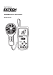
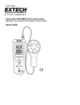
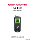
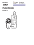
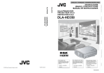
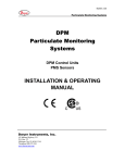
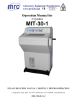
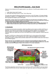
User Guide Heavy Duty Pitot Tube Anemometer and Differential Pressure Manometer Model HD350 Introduction Congratulations on your purchase of the Extech HD350. This handheld meter measures and displays air velocity (speed), air flow (volume), ambient air temperature, and gauge/differential pressure. This meter is shipped fully tested and calibrated and, with proper use, will provide years of reliable service. Features Pitot tube Anemometer measurements for Air Velocity and Air Flow (volume). Manometer (Differential Pressure) Measurements. Simultaneous display of Air Flow or Air Velocity, Temperature, and Pressure. 5 selectable pressure units of measure. Record up to ninety-nine (99) readings (in meter’s internal memory) for each of the three measurement types (Air Velocity, Air Flow, and Pressure) for a total of 297 readings. USB port for connection to a Personal Computer (PC) for real time datalogging of up to 5500 readings stored on the PC. Large backlit LCD display. Data Hold and Maximum, Minimum, Average memory (MIN/MAX/AVG). Auto Power OFF (can be disengaged). 2 HD350-EU-EN- V3.0 7/10 Meter Description 1. Pitot tube. Hold the tube in the flow of air to take a reading 2. Pressure Manometer hose 1 Black 3. Pressure Manometer hose 2- White 4. Pressure Connector (+) 1 5. Pressure Connector (-) 6. Temperature sensor 7. LED display shows readings, units, setup parameters, and user alerts 6 8. PC interface jack: Use the supplied cable to connect the meter to a PC 5 9. Upper Keypad: 7 8 F/C : Press to change the unit of measure for Temperature. Also functions as an up arrow key UNIT : Press to change the unit of measure for Pressure, Air Velocity, and Air Volume (Flow). Also functions as a down arrow 2 4 3 9 10 AVG / REC: Used to obtain the Average for multi-point measurements in either FLOW or VELOCITY modes. Up to twenty (20) points can be 11 averaged. Press and hold this button for 3 seconds to access the data Recall mode (REC) : Momentary key presses turn the backlight on and off. Press and hold this SETUP button for 3 seconds to enter or exit the Setup mode (discussed later in this guide) 10. Lower Keypad: MAX/MIN: Press to record and store the highest, lowest and continuous moving average readings for single point measurements. Press and hold this button to exit this function SAVE / CLEAR: Press to store a reading. In recall mode, pressing this button clears a data sample. P/V/F: Press to select Pressure (P), Air Velocity (V), or Air Flow (F) HOLD / ZERO: Momentary presses freeze and un-freeze the displayed reading. Press and hold the button to ZERO (OFFSET) the displayed reading 11. On/Off button : Press to turn the meter ON or OFF KEYPAD NOTE: In Setup mode several buttons have special uses not detailed above but are described in subsequent sections of the manual. NOTE: Battery Compartment, Tilt Stand, and Tripod Mount are located on the reverse side of the meter. 3 HD350-EU-EN- V3.0 7/10 Display Description 1. Elapsed timer display units (min:sec or hour:min) 2. Pressure, Velocity, Flow and Temperature mode indicators 3. Primary Measurement Display 4. Units of measure for air velocity 5. Units of measure for pressure 6. Indication that the meter is communicating with the PC 7. Auto Power Off mode indicator 8. Low battery indicator 9. Duct Shape indicator 10. Data Hold indicator 11. Height/Width (rectangular duct) or Diameter (circular duct) 12. Setup mode indicator 13. CLEAR icon appears as data is deleted from the meter’s internal memory 14. Reading (sample) number 15. Memory indicator 16. REC, MAX, MIN and AVG indicators 17. Temperature units for the primary display 18. Units of measure for air flow 19. Temperature units for the secondary display 20. Secondary display (Temperature) 4 HD350-EU-EN- V3.0 7/10 Setup Mode Changing Setup Options The Setup mode is used to select the shape/dimensions of an air duct for Air Flow Measurements, engage/disengage Sleep mode (auto power OFF), hide/view measurement types, and selectively delete (clear) readings from the 99-location internal memory. The meter stores these settings in its internal non-volatile memory. Setup Options Option Menu item Settings Air Duct dimension units Unit Set duct dimension units to inches (‘in’) or centimeters (‘cm’) Air Duct Shape Duct Shape Rectangle or Circular duct symbol Air Duct Area DECI/99999 Decimal place and 5-digit number to represent the area Meter Configuration (select the measurement parameters to use; the others will be hidden) Type Auto Power Off (Sleep) mode SLEEP ON or OFF Delete Stored readings ALL Use the SAVE/CLEAR button to choose the reading type(s) to delete. Select CLEAR to delete. Type 1 (show Pressure and Velocity) Type 2 (show Velocity and Flow) Type 3 (show all measurement types) Entering or Exiting Setup Press and hold the SETUP button for 2 seconds to enter or exit the Setup mode. When the meter is in Setup mode, the display indicates ‘SETUP’. Changing a Setup Option 1. Use the ▲▼arrow keys to scroll through the setup options. 2. Press the AVG REC button when the desired setup parameter is displayed. 3. Use the arrow keys to scroll to the desired setting. 4. Press the AVG REC button to store the new setting in memory. Note: The Setup mode is disabled when the meter is in the MIN-MAX-AVG mode. 5 HD350-EU-EN- V3.0 7/10 Air Duct Properties (for Air Flow Measurements) Air Duct - Unit of Measure: 1. Press and hold the SETUP button for two (2) seconds to enter the Setup mode. The SETUP display icon will appear. 2. Use the arrow keys to scroll to the UNIT display. 3. Press the AVG REC button and the display will show ‘in’ (inches) or ‘cm’ (centimeters) at the bottom of the LCD in relatively small digits. 4. Use the arrow keys to change the unit of measure. 5. Press the AVG REC button to save the setting. Continue with Step 6 below to set the shape and size of the duct. Air Duct – Shape: 6. Continuing from Step 5 above, press the AVG REC button to show the rectangle or circle shape. 7. Use the arrow keys to select the shape that matches the air duct in question (rectangular or circular duct) 8. Press the AVG REC button to store the setting and proceed to Step 9 to enter the air duct area. Air Duct – Area (W x H) for Rectangular Ducts: 9. Continuing from Step 8 above. Skip to Step 18 for Circular ducts. For rectangular air ducts, the ‘W=’ icon (duct width) will appear. The display will show DECI (decimal) at the top and a 5-digit number directly below. The 5-digit number is used to program the duct’s width. 10. Use the arrow keys to move the decimal to the desired position 11. Press the SAVE CLEAR button to move the display cursor to the right-most digit. The right-most digits will flash indicating that it is ready to be changed if desired. 12. Use the arrow keys to change the value of the right-most digits in the range of 0 to 9. 13. Use the SAVE CLEAR button to move to the next digit and change its value if desired using the arrow keys. Continue in this manner until the duct width edit is complete. 14. Press the AVG REC button to store the Width value and move to the Height (H) editing procedure. 15. Edit the Height value in the same manner as the Width value. 16. Press the AVG REC button to store the Height value. 17. Press and hold the SETUP button for two (2) seconds to exit the Setup mode. The ‘SETUP’ display icon will switch off. 6 HD350-EU-EN- V3.0 7/10 2 Air Duct – Area (pi*r ) for Circular Ducts: 18. Continuing from Step 8 above. For circular air ducts, the ‘D=’ icon (duct diameter) will appear. The display will show DECI (decimal) at the top and a 5-digit number directly below. The 5-digit number is used to program the duct’s width. 19. Use the arrow keys to move the decimal to the desired position 20. Press the SAVE CLEAR button to move the display cursor to the right-most digit. The right-most digits will flash indicating that it is ready to be changed if desired. 21. Use the arrow keys to change the value of the right-most digits in the range of 0 to 9. 22. Use the SAVE CLEAR button to move to the next digit and change its value if desired using the arrow keys. Continue in this manner until the duct diameter edit is complete. 23. Press the AVG REC button to store the Width value and move to the Height (H) editing procedure. 24. Press and hold the SETUP button for two (2) seconds to exit the Setup mode. The ‘SETUP’ display icon will switch off. Meter TYPE Configuration The TYPE feature in the Setup mode allows the user to hide/view measurement types (Air Velocity, Air Flow, and Pressure). The meter can be configured for Type 1 (show Pressure and Velocity measurements); Type 2 (show Air Velocity and Air Flow measurements); Type 3 (show all measurement types). The steps below outline the configuration process: 1. Press and hold the SETUP button for two (2) seconds to enter the Setup mode. The SETUP display icon will appear. 2. Use the arrow keys to scroll to the ‘TYPE’ display. 3. Press the AVG REC button and the display will show ‘1’, ‘2’, or ‘3’ at the top of the LCD. 4. Use the arrow keys to select the desired type number. If in doubt, select ‘3’ to view all measurement types. 5. Press the AVG REC button to save the setting. 6. Press and hold the SETUP button for two (2) seconds to exit the Setup mode. The ‘SETUP’ display icon will switch off. Auto Power OFF (Sleep) Mode Sleep mode automatically switches the meter OFF after 20 minutes of inactivity. This feature goes a long way in preserving battery life. To disengage/engage this feature: 1. Press and hold the SETUP button for two (2) seconds to enter the Setup mode. The SETUP display icon will appear. 2. Use the arrow keys to scroll to the ‘SLEEP’ display. 3. Press the AVG REC button and the display will show ‘ON’ or ‘OFF’ at the top of the LCD. 4. Use the arrow keys to change from ‘OFF’ to ‘ON’ or ‘ON’ to ‘OFF’. 5. Press the AVG REC button to save the setting. 6. Press and hold the SETUP button for two (2) seconds to exit the Setup mode. The ‘SETUP’ display icon will switch off. 7 HD350-EU-EN- V3.0 7/10 Delete (Clear) Stored Readings As described in the dedicated section on the meter’s internal memory feature, the meter can store up to ninety-nine (99) readings for instant recall. The CLEAR feature in the Setup mode allows the user to selectively delete stored readings by type or to delete all of the readings. 1. Press and hold the SETUP button for two (2) seconds to enter the Setup mode. The SETUP display icon will appear. 2. Use the arrow keys to scroll to the ‘ALL’ display. 3. Press the AVG REC button and the display will show ‘YES’ or ‘NO’ at the top of the LCD. 4. Use the arrow keys to select ‘YES’. 5. Under the ‘YES’ display the measurement functions are listed in smaller digits (PRESS-VEL-FLOW). Use the SAVE CLEAR button to select the measurement types to delete. 6. Press the AVG REC button to clear the selected reading types. The meter will beep indicating that that the delete process was successful. 7. Press and hold the SETUP button for two (2) seconds to exit the Setup mode. The ‘SETUP’ display icon will switch off. 8 HD350-EU-EN- V3.0 7/10 Measurements Pressure Measurements 1. Turn the meter ON using the power button 2. Use the P/V/F button to scroll to the Pressure Measurement Mode (the ‘PRESS’ display icon will appear). 3. The Primary display shows gauge or differential Pressure measurements (in the range of ±5000Pa) in the following units of measure (selectable): PSI, mbar, Pa, inH2O, and mmH2O. To change the displayed unit of measure for Pressure, use the UNIT ▼button. 4. Ambient Temperature readings will appear at the top right of the LCD on the Secondary display digits. To change the displayed unit of measure for Temperature, use the F/C ▲button. 5. For Gauge Pressure Measurements, connect a single hose to the INPUT (+) port and leave the REF (-) port unconnected. 6. With the other end of the connected tubing open to ambient conditions, press and hold the HOLD ZERO button until the meter display flashes a series of ‘o’ symbols and then displays zeros. This nulls the meter’s Pressure display. 7. Connect the attached hose to the pressure under test and read the displayed pressure value. 8. For Differential (Manometer) Pressure Measurements, connect tubing to the INPUT (+) port and the REF (-) port. The meter will now display a positive pressure reading if the INPUT (+) pressure is greater than REF (-) and a negative reading if REF (-) is greater than INPUT (+). . Air Velocity (Speed) Measurements 1. Press the PVF button to select the Air Velocity measurement mode; the VEL display icon will appear on the LCD. 2. Use the UNIT ▼ button to select the desired measurement unit (m/s, ft/min, km/h, MPH, knots). 3. The meter’s primary display digits will represent the air velocity measurement. The meter’s secondary display digits (top right of LCD) displays the ambient temperature measurement. 4. Connect the hoses to the Pitot tube and to the Meter. The “Input (+)” pressure port on the Meter connects to the white hose from the total pressure connection of the Pitot tube. The “Ref (-)” pressure port on the Meter connects to the black hose from the static pressure connection of the Pitot tube. 5. If the Velocity measurement is a negative value on the display, ensure that the hoses are attached to the correct ports on the Meter and the Pitot tube. 6. With the Pitot tube open to ambient conditions press and hold the HOLD ZERO button for 2 seconds to zero the display. 7. Put the mouth of the Pitot tube in the direction of the oncoming air mass under test and read the Air Velocity measurement value on the LCD. 9 HD350-EU-EN- V3.0 7/10 Air Flow (Volume) Measurements 1. Press the P/V/F button to enter the Air Flow (Volume) mode (FLOW will appear on the LCD). The Primary display area will show the Air Flow measurement. 2. Use the UNIT ▼button to select the desired unit of measure (CMM or CFM). 3. To view the currently programmed duct area and shape: • Press the P/V/F button three more times to access the duct size/dimensions display. The duct shape selection (rectangle or circle) will appear on the lower lefthand area of the LCD and the Area value will be shown above it. • For Circular ducts, the Diameter (D) of the duct will be shown. • For Rectangular ducts, the Width value (W) will be shown first; press the P/V/F button again to switch to the Height (H) value display. • Note that the Meter stores/displays the last duct shape and size programmed by the user. To change the duct size and/or shape refer to the earlier SETUP MODE section. • Press the P/V/F button again to return to the AIR FLOW screen. 4. Now take an air velocity measurement as described in the previous section on Air Velocity (ignoring the unit of measure discussions). The meter will display Air Flow (Volume) in Cubic Feet per Minute (CFM) or Cubic Meters per Minute. The meter calculates Air Volume (Flow) by measuring Air Velocity and taking into account the area of the duct. Ambient Temperature Measurements The Secondary display area (top right of LCD) indicates the ambient temperature sensed by the thermometer located at the top middle of the meter (between the two pressure connection posts). To change the displayed unit of measure for Temperature, use the F/C ▲button. The only instances where the Secondary display area will not indicate temperature are when the meter is in the SETUP mode or when the Elapsed Timer is shown. Additional Functions Data Hold 1. Press the HOLD ZERO button to freeze the presently displayed reading on the display. The display will show the HOLD icon while in the Data Hold mode. 2. Press the HOLD ZERO button again to exit the Data Hold mode and return the meter’s display to real time operation. 10 HD350-EU-EN- V3.0 7/10 MIN, MAX, and AVG Readings 1. Press the MIN-MAX button to start a MIN-MAX-AVG session. The elapsed timer will start (shown on the top right, secondary LCD display area) and indicate the minutes and seconds that have elapsed since the session started. 2. Use the P/V/F button to select the measurement type to review (Pressure, Air Velocity, or Air Flow). 3. Use the MIN-MAX button to step through the MAX (maximum reading), MIN (minimum reading), and AVG (average reading) for the selected measurement type that has been captured since the MIN-MAX-AVG session began. The elapsed time value is captured along with the MAX and the MIN reading 4. Press and hold the MAX-MIN button for at least two (2) seconds to exit the MIN-MAXAVG mode. Storing, Recalling, and Averaging Readings The HD350 can store up to 99 readings in its internal memory for each of the three measurement modes (Air Velocity, Air Flow, and Pressure) for a total of 297 readings. 1. Momentarily press the SAVE CLEAR button to store a reading. When the internal memory is full (99 readings) the meter will display ‘FU’ (FULL) and beep when another reading is attempted to be stored. 2. After a series of readings are taken, press and hold the AVG REC button to enter the ‘REC’ (Recall) mode and begin recalling the stored readings. 3. Use the arrow keys to scroll through the stored readings. The reading sample number is shown at the bottom right-hand corner of the display. 4. To show an average of all of the stored readings, press the AVG REC button while in the Recall (REC) mode. 5. Use the P/V/F button at any time during the Recall process to switch between the three modes of measurement (Air Velocity, Air Flow, and Pressure). 6. To exit the Recall mode, press and hold the AVG REC button for at least (2) seconds. The ‘REC’ display icon will switch OFF and the meter will return to the normal operating mode. Deleting Stored Readings Use the P/V/F button to select a measurement mode (Air Velocity, Air Flow, or Pressure) 1. 2. 3. 4. 5. To clear one reading at a time, Press and Hold the AVG REC button for at least two (2) seconds to enter the Recall mode (the ‘REC’ icon will appear). Use the arrow keys to scroll to the desired reading that is to be deleted. Press the SAVE CLEAR button to delete the selected reading. Note that the number of samples on the sample counter (lower right) will have decreased after the reading is deleted. Press and hold the AVG REC button for at least two (2) seconds to exit the Recall (REC) mode. To clear ALL of the readings simultaneously, refer to the SETUP MODE section earlier in this manual. 11 HD350-EU-EN- V3.0 7/10 Battery Replacement When the low battery indicator appears on the display (or if the meter does not switch on when the power button is pressed), please replace the battery. To replace the battery: 1. Open the battery compartment by sliding the meter’s rear panel in the direction of the embossed arrow. 2. Replace the 9V alkaline battery 3. Replace the battery compartment cover. 4. You, as the end user, are legally bound (EU Battery ordinance) to return all used batteries, disposal in the household garbage is prohibited! You can hand over your used batteries / accumulators at collection points in your community or wherever batteries / accumulators are sold! Disposal: Follow the valid legal stipulations in respect of the disposal of the device at the end of its lifecycle USB PC Interface and Software The HD350 is equipped with a USB communication jack on its upper left side. The supplied communications cable connects to this jack and to a USB port on a PC. The supplied software allows the user to view and save readings to the PC. Instructions for use and features are detailed in the supplied software HELP utility. 12 HD350-EU-EN- V3.0 7/10 Specifications General Specifications Display Measurements Multi-function LCD with Backlighting Air Velocity: m/s, km/h, ft/min, knots, mph; 3 3 Air Flow: CMM (m /min) and CFM (ft /min); Pressure: psi, mbar, inH2O, mmH2O, Pa Air Temperature: °C and °F Data Hold Freezes displayed reading Response Time 0.5 seconds (typ.) Linearity / Hysteresis ±0.29 F.S. MIN-MAX-AVG Record and Recall lowest, highest, and average readings Auto Power OFF Automatic shut off after 20 minutes (can be disengaged) PC Interface USB PC Communication with supplied software and cable for data acquisition Low battery indication Battery symbol appears on the LCD Power supply 9V Battery Operating conditions 0 to 50 C (32 to 122 F) Storage conditions Relative Humidity o o o o -10 to 60 C (14 to 140 F) o Non-condensing (<10 C) 90%RH o (10 to 30 C) 75% RH o (30 to 40 C) 45% RH o (40 to 50 C) without condensation Dimensions / Weight Main instrument: 210 x 75 x 50mm (8.2 x 2.9 x1.9") Weight 280g (9.8 oz.) 13 HD350-EU-EN- V3.0 7/10 Air Velocity Specifications Air Velocity Range Resolution m/s (meter per second) 1 to 80.00 0.01 ft/min (feet per minute) 200 to 15733 1 km/h (kilometers per hr) 3.5 to 288.0 0.1 MPH (miles per hour) 2.25 to 178.66 0.01 Knots (nautical mph) 2.0 to 154.6 0.1 Accuracy ±(1%FS + 5digits) @ 5.00 to 10.00m/s Air Flow Specifications Air Flow Range CFM (cubic feet per minute) 0 to 99.999ft /min Resolution CMM (cubic meters per minute) 0 to 99.999m /min 3 0.0001 to 100 3 0.001 to 100 Manometer Specifications o Accuracy ±0.3% F.S. (Full Scale) at 25 C Repeatability ±0.2% (Max ± 0.5% F.S.) Linearity/Hysteresis ±0.29% F.S. Pressure Range ± 5000 Pa Maximum Pressure 10psi Response Time 0.5 Seconds typical Range Indicator Over range: Err.1; Under range: Err.2 Units Range Resolution PSI 0.7252 0.0001 mbar 50.00 0.01 inH2O 20.07 0.01 mmH2O 509.8 0.1 Pa 5000 1 Temperature Specifications Temperature Range o C o F o 0 to 50.0 C o 32.0 to 122.0 F 14 Resolution Accuracy 0.1 ±1.5 C 0.1 ±3.0 F o o HD350-EU-EN- V3.0 7/10 Useful Equations Calculating the Area for rectangular or square ducts Rectangle: Area (A) = Height (b) x Width (a) Circle: Area (A) = π x r2 (Where π a = 3.14 and r2 = radius x radius) r b Cubic equations 3 2 CFM (ft /min) = Air Velocity (ft/min) x Area (ft ) 3 2 CMM (m /min) = Air Velocity (m/sec) x Area (m ) x 60 NOTE: Measurements made in inches must be converted to feet or meters. Copyright © 2010 Extech Instruments Corporation (a FLIR company) All rights reserved including the right of reproduction in whole or in part in any form. 15 HD350-EU-EN- V3.0 7/10