1
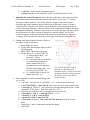
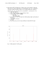
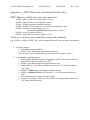
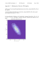
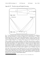
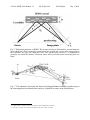
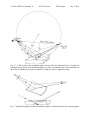
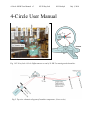
4-Circle 18KW User Manual v5 NU X-Ray Lab M.J. Bedzyk July 1, 2010 Beamline Components: (In sequence, starting from source, refer to Fig. 2.) 18KW Ultrex Rigaku Rotating Anode (donated by Abbott Labs in 2006) • Cu Anode: Cu Kα1 λ = 1.5406 Å Cu Kα2 λ =1.54443 Å • Point Source: Normal Focus 0.5 mm x 10 mm, 18 KW max power o The effective source size should be 0.5-mm high by 1-mm-wide due to 6° take-off angle . But we measure the width to be 0.5 mm wide. (See Fig. 3.) • Nominal operating power: 50 KV, 240 mA • Huber slits for controlling horizontal and vertical divergence (See Fig. 3.) o Nominal setting: hsdgap= 0.7 mm wide by 14-mm-high o 1 full turn of the dial on a Huber slit translates the blade 0.50 mm. • Graphite (002) Grade ZYA ( < 0.5° mosaic) from Advanced Ceramics Corp. o Size: 25 x 25 x 2 mm o Para-focusing in the horizontal direction o Sagittal-focusing in the vertical direction with Rs = 225 mm o 2d002 = 6.708 Å, Cu Kα1 θ = 13.28° o 1 to 1 focusing, F1=F2=F= RS /sinθ = 980 mm. This is the distance from the source to the mono and from the mono to the sample. (See Appendix D for ray diagrams illustrating Parafocusing and Sagittal focusing.) • Incident beam intensity monitor (NaI detector collecting scattered x-rays from Co coated Kapton foil) I0 = 8900 cps at hsdgap = 0.7 mm and vsdgap = 14 mm. • Huber incident beam slits for passing Cu Kα1 and blocking Cu Kα2 o Nominal setting ka2cen = 0, ka2gap = 0.5 mm-wide by 1-mm high • Huber 4-circle diffractometer o Motorized Z-sample, zsamp = 0 should put pin in COR (Center of Rotation) o Huber 1006 X-Y-χ−φ goniometer o Sample holder o 2-theta arm: (Nominal settings) guard slit ( gshhcen = 0.64, gshgap = 1.1, gsvcen = 1.4, gsvgap = 8 ) XIA filter box, ( T = 0.24 x 0.01 for STB straight thru beam) (See Appendix A for SPEC Macros for controlling XIA Filter Box.) detector slit, ( dshhcen = 0.05, dshgap = 1.0, dsvcen = 1.9, dsvgap = 12 ) Cyberstar NaI X-ray detector (0.3µsec, 740V, Gain =8, LL=2.5, UL=6.5) • Auxillary equipment: o Laser Level on Tripod o X-ray Eye o Goniometer pin o High-power zoom lens camera Β Operating Procedures: 1. Introduction: In describing the procedures for operating the 4-circle, we will use as an example the following MBE grown thin-film sample: a. 200 Å BaTiO3 / 20 Å SrTiO3 / Si(001) substrate b. The STO (SrTiO3) fillm will be very difficult to sense because it is so thin. c. We will study the thicknesses of the layers by low-angle XRR d. We will determine the miscut angle of the surface relative to the Si(001) e. We will determine the single crystal quality of the BTO film