1
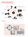
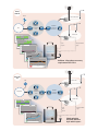
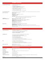
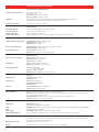
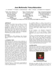
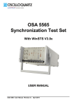
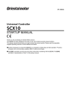
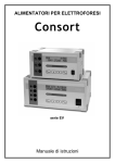
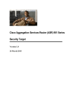
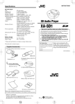
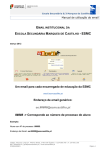
Calnex Sentinel
The all-in-one field sync tester
for 4G and 3G Mobile Backhaul,
Financial Networks and
Power Comms
Platform Highlights
4G/LTE/3G Network Test
PTP, NTP, SyncE and TDM in one box
Allows you to test all legacy and new networks with one box
Long-term measurement capability to find intermittent issues
Send measurements back to lab/vendor to replay to fix issues
Built-in Pass/Fail limits when measuring the network for
Node-B: Ericsson RBS6000, Huawei 3900, NSN Flexi, etc.
eNodeB: Huawei, ZTE, Ericsson, AlcatelLucent, NSN, etc.
Small cells supporting PTP or NTP
Cell-site Routers and PTN (Cisco ASR901, ALu 7705-SAR,
Tellabs 860x, Huawei PTN, etc.)
Boundary Clocks (BCs) and Transparent Clocks (TCs)
Embedded GPS receiver and Rubidium (Rb)
Optional battery for Rb to maintain holdover during transport
Easy calibration – ‘Calibrate-Once’ or ‘Continuous Auto-calibration’
Fit for the field, fit for the network
Local or remote operation
Monitor-mode or Pseudo-slave mode
Web and Ethernet for control, USB connectivity for external storage
Portable, rugged and easy-to-use
Modular, multi-port tester
Measurement reports in pdf format
SDH/Sonet Network Test
Simultaneous measurement of multiple TDM (PDH/SDH/Sonet) signals
Speed up TDM network Sync testing
Improve efficiency of debug
Standard industry masks per G.811/G.812/G.813/G.823/G.824
Measure ALL parameters at the SAME time
Network PDV, network Wander (SyncE, TDM) and Clock output (frequency and phase)
Identifies what the issue is and where it’s coming from (network, switch, nodeB etc.)
Flexible network connection options
As a Pseudo slave connected to network switches
As a network monitor, monitoring live network PDV
Test networks for Frequency & Phase
ITU-T G.8265.1 for frequency
G.8275.1, G.8275.2 for Time/Phase
Standard industry masks and packet metrics
ITU-T G.8261.1
MTIE/TDEV/MAFE/FPP/FPC
Test networks with Boundary Clocks and Transparent Clocks
Qualify your existing network – identify how many BCs/TCs are needed
Validate network and equipment performance to ITU-T limits
Test that the network is suitable for LTE-A and TDD-LTE
Pinpoint which BC/TC contributes significant timing error
Lab quality performance in an
easy-to-use, portable package
No need to carry a truck
load of equipment – it’s
now all-in-one
Just two steps to run the test:
1. Run Signal Check to auto-discover signals
2. Start all measurements at the same time
Small enough to
take on flights as
hand-luggage
Remote operation
and monitoring from
NOC/Office
Big touchscreen
and user-friendly
interface
Train Rb in the
lab then switch
off, drive to the
test site and
start testing
Pass/Fail ITU-T
and Vendor limits
for easy analysis
Fail
Capture and Replay – send
measurement files back to
Vendor/Labs to fix issues
Detailed measurement
report in pdf format
Applications
TDM
STM-1
ADM
STM-1
SONET/SDH
WDM/OTN
E1
ADM
E1
STM-1
E1
ADM
Pass Pass Pass Pass Pass
Up to 6
measurements
at the same time
Fail
LTE-A/
TDD LTE
PRTC
Macro eNodeB
PTP Slave
EPC
T-BC
IP/MPLS
or Ethernet
Core
T-BC
T-BC
IP/MPLS
or Ethernet
Backhaul
Small Cells
Forward PDV
PTP Slave
Reverse PDV
PTP
SyncE
FPP
Pass
E1/T1/10 MHz
1pps
GPS
Frequency
Phase
Validate 1.5μs phase accuracy
requirement for LTE-A
Pass
1.5us
Fail
FDD-LTE/
3G
PRC
Macro Cell
PTP/NTP
Slave
IP/MPLS
or Ethernet
Core
EPC/RNC
IP/MPLS
or Ethernet
Backhaul
Small Cells
Forward PDV
PTP/NTP
Slave
FPP
PTP
NTP
SyncE
Pass
E1/T1/10 MHz
1pps
Frequency
GPS
Pass
Check whether
PTP/NTP delivers
Sync within specs
Clock Module Specifications
Predefined Signal/Clock Types
• 1pps (PTP slave recovered clock)
• 8 kHz (frame clock)
• 64 kHz /64 kbit/s (E0 / DS0)
• 1.544 MHz/1.544 Mbit/s (T1/DS1 clock/data)
• 2.048 MHz/2.048 Mbit/s (E1 clock/data)
• 5 MHz/10 MHz (Freq. reference)
• 25 MHz/125 MHz/156.25 MHz (SyncE clock rate)
• 34 Mbit/s (E3), 45 Mbits/s (DS3)
• 155.52 MHz/155 Mbit/s (STM-1/STS-3 clock/data)
User-defined Clock Types
User-defined signal types from 0.5 Hz to 200 MHz in 1 Hz steps. Note: (symmetrical, unipolar clock signals)
Measurement Ports Number of Ports: 2 per module
Connector: BNC
Impedance: 75 ohm, VSWR <2:1 or 1M ohm
Voltage Range: ±5.00 V
Sensitivity: 60 mVpp
Signal Type: Symmetrical pulse (Clock signal); Unsymmetrical repetitive pulse (Clock signal);
HDB3-coded data (Data signal); AMI B8ZS, B3ZS (Data signal)
Test Modes (MTIE and TDEV Masks) Masks can be applied for TIE, MTIE and TDEV graphs.
1pps: Time Error limit (e.g. ±1.5 µs)
PRC/SSU/SEC: Masks for G811/G812/G813-clocks (ETSI 300 462-3)
Networks: According to G.823/G.824/G.8261/G.8261.1
SyncE: According to G.8261, G8262
ANSI-standard: DS1 and OC-N masks
User-defined: Defined by the user
Graph Display Display Modes: TIE, MTIE, TDEV, ADEV, FDEV, RTIE, MRTIE
Update Rate: approx. once/second
Number of Graphs: Up to 6 graphs of the same type can be over-laid on screen. Color coded.
Masks on Screen: Up to 6 MTIE, MRTIE and TDEV masks according to selected test mode.Pass/Fail result available for each mask
Ethernet Module Specifications
Synchronous Ethernet
• SyncE clock measurement
• Conformance to G.8261 and G.8262 masks (MTIE/TDEV)
• Additional metrics display: FDEV, ADEV, MRTIE
• Extract and display ESMC message (SSM)
• Generate and change ESMC
IEEE1588v2 PTP
• Forward (Sync) PDV, Reverse (DelReq) PDV and Network Delay
• Raw PDV (vs time and distribution graphs)
• Selected Packet PDV (vs time and distribution graphs)
• Cluster/band packet selection
• Pseudo-Slave or Monitor Mode
• Layer 3 (IPv4/UDP) Multicast/Unicast
• 5 ns resolution timestamp, better than 1 ns accuracy
• Captured PDVs can be replayed on Calnex Paragon-X for troubleshooting
NTP
• Forward (Server) PDV in Monitor mode
• Raw PDV (vs time and distribution graphs)
• 5 ns resolution timestamp, better than 1 ns accuracy
• Captured PDVs can be replayed on Calnex Paragon-X for troubleshooting
Measurement Ports Number of Ports: 1 per module
Connector: RJ45 for 10/100/1000 bT, SFP (SFPs not supplied) 100M/1GbE
Platform Specifications
Reference Clock
Built-in Rubidium reference or external reference input 1, 5 or 10 MHz
Resolution
200 ps rms
Sample Rate
Up to 100 Sa/s depending on number of parallel measurements
Internal Data Storage
Up to 5M TIE values
External Data Storage
On USB memory stick
Start/Stop
Via START/STOP key
Signal Check Parameters
Signal type (Clock, Data or Unknown); Frequency (for clock signals); Pulse width (for data signals);
Voltage peak-peak (min. 120 mVp-p)
Display
Color TFT, 8.4”, 800x600 pixels, resistive touchscreen
Specification is subject to change without notice.
Platform Specifications (continued)
Stability Versus Temperature: Internal Time Base Stability (holdover)
Calibration
Principle: Closed Case Calibration with automatic adjustment of the Rubidium timebase,
using Cs-based, or GPS-controlled Rb-based, or built-in GPS reference
20° to 26°C: <1x10-11 (typ.)
0° to 50°C: <1x10⁻¹⁰
Ageing Rate: 24h: <5x10-11 per month
Warm-up Stability: 12 min to <1x10⁻⁹
Calibration Uncertainty<2x10-12 + Cal. Ref. Freq. Uncertainty
GPS-disciplining Built-in GPS Module 12 channels, TRAIM GPS receiver, high sensitivity
Time Accuracy to UTC
± 25 ns at 1σ after 24 hours lock
Frequency Accuracy
2x10-12 averaged over 24 hours
GPS Disciplining Modes
Always disciplining, always in holdover, disciplining only between measurements
External References
Frequency Reference Input (std)
Input Frequency: 10 MHz, 5 MHz or 1 MHz
Voltage Range: 0.1 Vrms to 5 Vrms
Impedance: approx. 50 ohm
External 1pps Timing Input Voltage Range: 0V to 0.8V (Low), 2V to 3.3V (High) into 50 ohm
Required Accuracy: ± 100 ns to UTC
GPS Timing Reference Antenna Input: N-type connector
DC-feed: +5V on center pin to active GPS antenna
Output References
Reference Frequency Output
Ref. Frequency: 10 MHz sine-wave
Output Levels: 1Vrms in 50 ohm
Impedance: approx. 50 ohm
1PPS Output
Source: Internal Rubidium oscillator
Output Logic Levels: TTL levels in 50 ohm
E1/T1 Output Module
Connector: Clock: BNC
Data: Isolated BNC
Frequency: 2.048/1.544 MHz
Output Level: Acc. to G703:10; ±1.2 V ±10% in 75 ohm
Interfaces
USB Device Port
Connector: Std USB type B
USB Version: 2.0
USB Host Port
Connector: Std USB type A
Max Supply Current: 400 mA
USB Version: 2.0
Ethernet
Communication Port: RJ45, 10/100 Base-T
Protocol: DHCP, HTTP, FTP, VNC
Remote
Operation Remote operation via VNC (open browser and enter IP address)
Environmental Data
Event Log: On screen log of measurement start/stop, duration, alarms, loss of data, loss of communication
link, etc. Log can be saved as text file.
Report Generation: Printable, custom designed measurement report in pdf format
Security: Password secured access to STA-61
TemperatureOperating: 0°C to 40°C
(30°C when charging Rb backup-battery)
Safety
EN 61010-1: 2011, CAT II, Pollution degree 2, Measuring category I, CSA C22.2 No 61010-1-04, UL 6010-1:2004
EMC
EN61326 (1997) + A1 (1998), CE
Power Supply
Line Voltage: 100 to 240 Vrms ±10%, 47 Hz to 63 Hz, <60 W
Optional Battery Backup
5 hours autonomy for rubidium only, to maintain internal timebase accuracy during transport
Mechanical Data
The chassis is suitable for field use, and can be operated on a bench (lying down) or on a floor (standing up).
The cabinet is shock resistant using bumpers
Dimensions (w x h x d)
320 x 388 x 126 mm (12.6” x 15.3” x 5”)
Weight Net <6 kg (13 lb); Shipping <7 kg (15 lb), with transport case <9kg (20 lb)
Specification is subject to change without notice.
Ordering Information
Calnex Sentinel Sync Analyzer with built-in GPS receiver. Needs one or more input modules (Option 610, Option 611).
Included with shipment: User manual on CD, line power cord, GPS antenna, antenna cable (20m), hard transport case,
calibration certificate, 1-year warranty and support.
Built-in Options
• Option 610: Clock module 1PPS/E1/T1, any clock up to 200 MHz (up to 3 per unit).
• Option 611: Ethernet module (PTP/NTP/SyncE). Includes SyncE/ESMC testing 100M and 1GbE (up to 3 per unit).
• Option 620: IEEE1588v2 and NTP PDV measurement software (one license per main unit).
• Option 630: Internal battery backup for Rubidium.
Optional Accessories
• Option 802: One year warranty extension.
• Option 803: Two years’ warranty extension.
• Option 75: 120 ohms balanced RJ45 to 75 ohms unbalanced BNC impedance converter (balun).
Related Products
Calnex Paragon-X
• Test 1588v2 PTP, SyncE, NTP, CES
and OAM up to 10G
• Stress-test equipment with realnetwork profiles from field-tests
to debug network issues
• Prove 1588v2 (PTP), Sync-E, CES,
Pseudowire, NTP, etc. implementations to ITU-T G.8261 etc.
• Test 1588v2 Ordinary Clocks,
Boundary Clocks and Transparent
Clocks
• Measure Time of Day (ToD), Phase
Calnex Paragon-t
• Speed up test time and reduce
test complexity with multi-clock
measurements
• Measure multiple outputs from
a chain of Boundary Clocks (BCs)
and Slave Clocks
• 4 x Frequency (SyncE/E1/
T1/2.048M/10M Wander)
measurements
• 4 x Phase (1pps accuracy)
measurements
• 4 x ToD display measurements
Calnex Paragon-m
• All Capture and Measure features
of Paragon-X
• 1588v2 and NTP PDV and
Standards and Vendor Metrics
(Pass/Fail evaluation)
• Sync-E Wander measurement to
ITU-T limits
• Clock measurements – 1pps, ToD,
E1/T1, including MTIE/TDEV to
ITU-T limits
• Thru-mode Network capture and
analysis
and Frequency
Calnex Solutions is a global leader in Test and Measurement solutions
for next-generation telecom networks. Our products help to prove new
technologies for Mobile Backhaul and Carrier Ethernet networks.
For more information on the Calnex product family, and to take
advantage of Calnex’s extensive experience in Packet Sync and OAM
testing technologies, contact Calnex Solutions today:
tel: +44 (0) 1506 671 416
email: [email protected]
© Calnex Solutions Ltd, 2013.
www.calnexsol.com