1
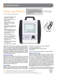
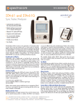
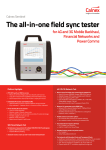
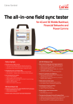
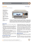
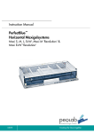
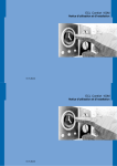
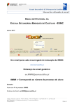
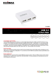
STA-61 and STA-61G Sync Tester/Analyzer • Synchronization test platform for Next Generation Networks (NGN) • Embedded time and frequency GPS/ Rubidium reference • Modular multi-input physical sync measurements: 2, 4 or 6 channels simultaneously • Automatic signal / clock identification of most popular telecom clocks, from 1PPS to STM1 • Modular multi-input packet sync measurements: Up to 3 gigabit Ethernet ports Shown with stand • SyncE and IEEE1588v2 Packet Delay Variation active probe • Comparison with standard masks • Very accurate built-in Rubidium reference for long term wander measurement • High sensitivity GPS receiver for timing measurement vs UTC Kaiserin-Augusta-Allee 8 10553 Berlin Germany 3 +49-(0)30-398981-0 5+49-(0)30-398981-39 9 [email protected] www.denk-stein.com • Portable and cost-effective instrument for field applications Vertrieb & Systemintegrator für Carrier + Corporate Networks • User-friendl local or remote operation The Pendulum STA-61 marks a new generation of instruments allowing the user to test and analyze synchronization quality and compliance in various types of networks. Where traditional instruments on the market are designed specifically for SDH/SONET or are dedicated SyncE or PTP testers, the STA-61 can do it all. This is a Sync Tester/Analyzer developed for Next Generation Networks (NGN), incorporating a mix of both traditional SDH/SONET core networks and IP-based backhaul networks. Portable and Cost-Effective Lightweight, with a handle and a size that fits as carry-on luggage on aircrafts, the STA-61 is designed to make it easy to bring wherever you want to use it. Place the sync tester/analyzer on a work-bench or use the stand for comfortable viewing when the instrument is placed on the ground. All these functions are packed together in an instrument that is still much less than the price of traditional testers on the market, makes STA-61 the most cost effective solution for field synchronization test. Truly User-Friendly Equipped with a large color LCD touch screen, showing metrics graphs in real-time during measurement, combined with on-display pass/fail information, this sync tester/analyzer is truly user-friendly. All it takes to start measuring is a simple 3 step operation: 1) Connect your signal(s) to test 2) Press SIGNAL CHECK to identify signal type 3) Press START Within a few minutes anyone could learn how to operate the STA-61. Modular, Future Proof, Versatile Sequential testing is no longer necessary if you want to measure wander on several access points in a station, the STA-61 can measure on up to 6 different test points simultaneously for physical sync and up to 3 for packet sync. The physical sync input module measures all standard telecom clocks, including 1PPS, E1/T1, 10 MHz, STM1, as well as user-defined clocks from 0.5 Hz to 200 MHz. The packet sync input module measures SyncE clock wander extracted from a 10/100 bT and 1 Gigabit Ethernet link and displays / manages SyncE message. Through the PDV measurement software option, this module also provides network PDV measurement, including raw PDV, selected packets PDV and related MTIE/ TDEV metrics, as well as floor packet metrics. It is possible to combine physical sync input modules and packet sync input modules, up to a total of 3 modules. The modular design ctracomco .spe . . . quality Q ... O 9001 . IS .. UK | 6A Beechwood | Chineham Park | Basingstoke, Hants, RG24 8WA | om . . . . . rp.c USA | 1565 Jefferson Road, Suite 460 | Rochester, NY 14623 | +1.585.321.5800 | FRANCE | 3 Avenue du Canada | 91974 Les Ulis, Cedex | STA-61 makes STA-61 future proof, buy your new sync tester/analyzer today and expand it with more input modules when you need it. Packet Sync Measurement STA-61 allows to measure synchronization conformance simultaneously at a packet sync level (based on SyncE and IEEE1588v2 technologies) and at a traditional physical sync level (1PPS, E1, interface) behind a packet synchronized device. Multiple packet sync measurements can be performed, whether it’s related to IEEE1588 v2 slave / boundary clock performance qualification or network Packet Delay Variation (PDV) characterization, SyncE wander can be also measured at any node in the network. Examples of Measurement Screens Multiple Signals with Multiple MTIE Masks: Here the MTIE of the two master and the two slave clock outputs are measured. The bottom solid lines are the master clocks, the top solid lines are the slave clocks. The dashed lines are color coded selected masks. The master clocks are well below all masks, and the slave clocks with the offset are above all masks, due to high frequency offset. Raw PDV: Raw PDV can be displayed either as PDV(t), showing the evolution of PDV depending on daytime, or as distribution. Forward and Reverse PDV measurements are available. STA-61 works as an active probe, meaning it acts in the network as a PTP slave, which can be associated to any visible PTP master in the network, allowing a precise forward and reverse packet delay measurement. Always Accurate The STA-61 includes a built-in high performance Rubidium oscillator which allows making sync measurements in places where no accurate frequency/time reference is available. This is key to field commissioning or trouble-shooting operations. In addition, the STA-61G has a built-in high sensitivity GPS receiver which slaves the internal reference to provide a few tens of nanoseconds absolute UTC time accuracy as well as sub10-11 frequency accuracy. No external calibration, and no calibration down-time, is needed with the STA-61G. Common Mode or Differential Wander Measurements You can compare all your signals under test to the integrated stable Rubidium atomic clock, or to an external high-stability standard, to show the absolute phase variations of all signals under test relative to the common reference clock. You can also define one of the input signals as the reference for all other input signals (differential TIE). This enables for example comparisons of outgoing vs. incoming sync clock in Network elements, and comparisons between a Grandmaster PTP and one or several PTP-slaves. For in-depth analysis, you can also read out cursor data and perform statistical analysis of your measurement. Sync Probe Mode The STA-61 can be used as a sync probe when connected to an IP network for a virtually infinite measurement duration. Thanks to the WanderView™ for STA-61 free companion software, powerful and user-friendly functions like remote control, data acquisition, post-processing, graph display, and report generation are available on a remote PC. Remote Operation Remote operation of the STA-61 can be facilitated in many ways. The STA-61 has a built-in web server including a VNC server. That means you could monitor and control the STA-61 via Ethernet in a standard VNC client anywhere in the world, running in a PC, or even in a smart phone. You can view the screen and the current measurement progress, and you can control the measurement by clicking the on-screen controls in the remote VNC client. You can also connect to the PC program WanderView™ for STA-61 via Ethernet. From WanderView™ you have full control of the STA-61 including continuous data streaming of measurement data, report generation and advanced post-processing and analysis. Time & Frequency GPS/Rubidium Reference STA-61 embeds a high performance time and frequency reference, which benefits from Spectracom know-how in terms of atomic clocks and high performance time-base disciplining. It provides 1PPS, 10 MHz and E1/T1 reference outputs for test cases where a wander free clock must be provided to the device under test. Floor Packet Count Display: Floor Packet metrics allow to characterize network ability to support frequency transfer through on IEEE1588, according to G.8261.1. The following graph shows Floor Packet Percentage. Technical Specifications: STA-61 Physical Sync Measurement Predefined Signal/Clock Types • 1PPS (PTP slave recovered clock) • 8 kHz (frame clock) • 64 kHz /64 kbit/s (E0 / DS0) • 1.544 MHz /1.544 Mbit/s (T1/DS1 clock/data) • 2.048 MHz / 2.048 Mbit/s (E1 clock/data) • 5 MHz /10 MHz (Freq. reference) • 25 MHz /125 MHz /156.25 MHz (SyncE) • 34 Mbit/s (E3) • 45 Mbits/s (DS3) • 155.52 MHz /155 Mbit/s (STM-1 clock/data) User-Defined Clock Types User defined signal types from 0.5 Hz to 200 MHz in 1Hz steps. Note: The signal under test must be a symmetrical, unipolar clock-type signal Measurement Modes Frequency: 1PPS/2s to 200 MHz Impedance: 75 ohm, VSWR <2:1 or 1M ohm Voltage Range: ±5.00 V Sensitivity: 60 mVpp Signal Type: • Symmetrical pulse (Clock signal) • Unsymmetrical repetitive pulse (Clock signal) • HDB3-coded data (Data signal) • AMI B8ZS, B3ZS (Data signal) External References Frequency Reference Input (standard) Packet Sync Measurement GPS Timing Reference (STA-61G) Synchronous Ethernet • SyncE clock extraction from Gigabit Ethernet interface • Conformance to G.8261 & G.8262 masks (MTIE/TDEV) measurement • Additional metrics display : FDEV, ADEV, MRTIE • Extract and display ESMC message (SSM) • Generate ESMC, and ESMC change pattern Input Frequency: 10 MHz, 5MHz or 1MHz Voltage Range: 0.1 Vrms to 5 Vrms Impedance: approx. 50 ohm External 1PPS Timing Input (STA-61G) Voltage Range: TTL in 50 ohm Required Accuracy: ± 100 ns to UTC Antenna Input: N-type connector DC-feed: +5V on center pin to active GPS antenna Output References Reference Frequency Output Ref. Frequency: 10 MHz sine-wave Output Levels: 1Vrms in 50 ohm Impedance: approx. 50 ohm Common Mode: Signals measured against the selected frequency reference (internal or external) Differential: One input signal is selected as reference, and all other signals are measured against this reference input. Absolute TIE (STA-61G only): 1PPS from DUT is measured against absolute 1PPS internal time reference, when GPS is locked (also called TOD measurement) IEEE1588v2 Packet Delay Variation PDV measurement applying to forward or reverse packet delay direction • Raw PDV (vs time, distribution graphs) • Selected Packet PDV (vs time, distribution graphs) • Cluster / band packet selection • MTIE, TDEV applied to Selected Packet PDV • Conformance to MTIE/TDEV masks • MATIE, MAFE • Floor Packet metrics (FPP, FPC, FPR) 1PPS Output Test Modes (MTIE and TDEV Masks) Physical Sync Input Module Interfaces USB Device Port Masks can be applied for MTIE and TDEV graphs. Draft: No mask PRC/SSU/SEC: Masks for G811/G812/ G813-clocks (ETS 300 462-3) Networks: According to G.823/G.824 SyncE: According to G.8261, G8262 ANSI-standard: DS1 and OC-N masks User-defined: Defined by the user Time Interval Error (TIE) Reference Clock: Built-in Rubidium reference or ext. reference input 1, 5 or 10 MHz Resolution: 200 ps rms Sample Rate: up to 100 Sa/s depending on number of parallel measurements Internal Data Storage: up to 5M TIE values External Data Storage: on USB memory stick Start/Stop: via START/STOP key. Signal Check Parameters: Signal type (Clock, Data or Unknown); Frequency (for clock signals); Pulse width (for data signals); Voltage peak-peak (min. 120 mVp-p) Graph Display Display Modes: TIE, MTIE, TDEV, ADEV, FDEV, RTIE, MRTIE Update Rate: approx. once/second Number of Graphs: Up to 6 graphs of the same type can be over-laid on screen. Color coded. Masks on Screen: Up to 6 MTIE, MRTIE and TDEV masks according to selected test mode. Pass/Fail result available for each mask Display: Color TFT, 8.4”, 800x600 pixels, resistive touchscreen Physical Sync Input Module Number of Channels: 2 per module Connector: BNC Interfaces • Number of channels: 1 per module • Connector: RJ45 for 10/100/1000 bT, SFP for optical gigabit Ethernet • IEEE1588v2 protocol supported as active probe • Layer 3 (IP/UDP), IPv4 • Any rate up to 128 p/s • Multicast / Unicast • End to End / Peer to peer • 5 ns resolution timestamp, better than 1 ns accuracy Common Features Internal Time Base Stability (hold-over) Stability Versus Temperature: 20° to 26°C: <1x10-11 (typ.) 0° to 50°C: <1x10⁻¹⁰ Ageing Rate: 24h: <5.10-11 per month Warm-up Stability: 12 min to <1x10⁻⁹ Calibration Principle: Closed Case Calibration with automatic adjustment of the Rubidium timebase, using Cs-based, or GPS-controlled Rb-based, 2.048, 5 or 10 MHz reference Calibration Uncertainty: <2x10-12 + Cal. Ref. Freq. Uncertainty GPS-disciplining of Internal Timebase - Model STA-61G Only Built-in GPS Module: 12 channels, TRAIM GPS receiver, high sensitivity Time Accuracy to UTC: ± 25 ns at 1 after 24 hours lock Frequency Accuracy: 2.10-12 averaged over 24 hours GPS Disciplining Modes: Always disciplining, always in holdover, disciplining only between measurements Source: Internal Rubidium oscillator Output Logic Levels: TTL levels in 50 ohm E1/T1 Output Module Connector: Clock: BNC; Data: Isolated BNC Frequency: 2.048/1.544 MHz Output Level: Acc. to G703:10; ±1.2 V ±10% in 75 ohm Connector: Std USB type B USB Version: 2.0 USB Host Port Connector: Std USB type A Max Supply Current: 400 mA USB Version: 2.0 Ethernet Communication Port: RJ45, 10/100 Base-T Protocol: DHCP, HTTP, FTP, VNC WanderView™ for STA-61 The STA-61 companion software provides full remote operation over IP networks. Operating System: Windows 2000/XP/ Vista/Windows 7, 32 or 64 bit OS Instrument Settings: All local instrument settings can be controlled Data Transfer: TIE-values in real-time transfer; stored TIE values; measurement settings; Instrument id • Continuous data streaming acquisition on remote PC, allowing unlimited measurement duration coupled with continuous connection • Dump mode data transfer at the end of mesurement, if connection is not continuously available Stored File Format: CSV, for easy export to other programs, like Time Monitor, Stable 32 or MS-Excel Metrics: MTIE, RTIE, MRTIE, TDEV, ADEV, MADEV, FDEV; all calculated functions are displayed in own graph windows Analysis: Cursor readouts, cursor delta, zooming in graphs, mean value, max value, min value, peak-peak value, std dev in any graph, either on full data set or data between cursors Technical Specifications: STA-61 Custom Mask Editor: User defined MTIE, MRTIE, and TDEV masks Event Log: On screen log of measurement start/stop, duration, alarms, loss of data, loss of communication link, etc. Log can be saved as text file. Multiple Graphs: Up to 6 measurements can be overlaid in the same graph for easy comparison Multiple Masks: Up to 6 masks can be overlaid in the same graph, with pass/fail indication Report Generation: Printable, custom designed measurement report in pdf format Security: Password secured access to STA-61 Mechanical Data Built-in Options The cabinet is suitable for field use, and can be operated on a bench (lying down) or on a floor (standing up). The cabinet is shock resistant, using bumpers. Dimensions (w x h x d): 320 x 388 x 126 mm (12.6” x 15.3” x 5”) Weight: Net <6 kg (13 lb); Shipping <7 kg (15 lb) Option 610: Physical sync input module Environmental Data STA-61GB Sync Tester/Analyzer with built-in GPS receiver and internal battery backup, multichannel synchronization tester/analyzer. Needs one or more input module options (Option 610, Option 611). Temperature: Operating: 0°C to 40°C Storage: -20°C to 70°C Safety: EN 61010-1:2011, CAT II, Pollution degree 2, Measuring category I, CSA C22.2 No 61010-1-04, UL 6010-1:2004 EMC: EN61326 (1997) + A1 (1998), CE Power Supply Line Voltage: 100 to 240 Vrms ±10%, 47 Hz to 63 Hz, <60 W Optional Battery Backup: 5 hours autonomy for rubidium only, to maintain internal timebase accuracy during transport Ordering Information STA-61G Sync Tester/Analyzer with built-in GPS receiver. Multi-channel synchronization tester/ analyzer. Needs one or more input module options (Option 610, Option 611). Included with Shipment: User manual on CD, line power cord, Calibration certificate, 3-year warranty1 1PPS/E1/T1, any clock up to 200 MHz Up to 3 per unit Option 611: Packet sync input module SyncE / ESMC testing on gigabitEthernet (up to 3 per unit) Option 620: IEEE1588 PDV measurement software (only one licence required by unit) Option 630: Internal battery backup for rubidium Optional Accessories Option 01: GPS antenna (STA-61G) Option 01/50: GPS antenna mounting kit (STA-61G) Option 02: GPS antenna cable, 20m (STA-61G) Option 27/61: Heavy Duty Hard Transport Case Option 75 : 120 ohms balanced RJ45 to 75 ohms unbalanced BNC impedance converter (balun) Option 90/61: Calibration certificate with protocol – Rubidium timebase Option 95/05: Extended warranty to 5 years OM-61: Printed User Manual The warranty period may vary dependent on country. 1 Kaiserin-Augusta-Allee 8 10553 Berlin Germany 3 +49-(0)30-398981-0 5+49-(0)30-398981-39 9 [email protected] www.denk-stein.com Vertrieb & Systemintegrator für Carrier + Corporate Networks Vertrieb | www.denk-stein.com March 11, 2013 - 4031 600 61101 - rev. 7 Specifications subject to change or improvement without notice. Spectracom is a business of the Orolia Group. © 2010 - 2013 Orolia USA, Inc.