1
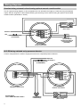
Wiring diagrams
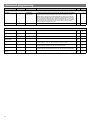
Standard wiring schematic also showing optional manual override switch
This is a general wiring diagram. In this configuration the unit will switch the supply to a luminaire using the switched
output, and dim using DALI or DSI. Manual dimming and switching can be achieved using the optional centre biased
retractive switch (MK K4900 or similar).
DIMMING
BALLAST
DIMMING LUMINAIRE
(DSI or DALI)
NEUTRAL
LIVE
CIRCUIT PROTECTION
(IF REQUIRED)
N
L/OUT
L
DIMDIM+
SW1/UP
SW2
DOWN
CENTRE BIASED
RETRACTIVE SWITCH
(240V SWITCHING)
(OPTIONAL)
ALC-DD DIMMING
OUTPUT PHOTOCELL
ALC-DD being switched on by presence detector
In some configurations it is useful to supply the sensor from a separate presence detector. .
NEUTRAL
LIVE SUPPLY
CIRCUIT PROTECTION
(IF REQUIRED)
N
L/OUT
L
N
L/OUT
L
DIM+
DIM-+
SW1/UP
SW2
DOWN
ALC-DD DIMMING
OUTPUT PHOTOCELL
PRESENCE DETECTOR
PLEASE NOTE!
CPC's OMMITTED FOR CLARITY
4
DIMMING
BALLAST
NON-DIMMING
LUMINAIRE(S)
DIMMING LUMINAIRE(S)
(DSI or DALI)