1
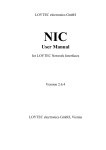
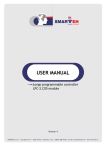
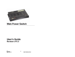
USER MANUAL
Longo programmable controller
LPC-2.OT1 operation terminal
Version 4
SMARTEH d.o.o. / Trg tigrovcev 1 / 5220 Tolmin / Slovenia / Tel.: +386(0) 388 44 00 / e-mail: [email protected] / www.smarteh.si
Longo programmable controller LPC-2.OT1 operation terminal
Written by SMARTEH d.o.o.
Copyright © 2005, SMARTEH d.o.o.
User Manual
Document Version: 004
March 31, 2006
i
Longo programmable controller LPC-2.OT1 operation terminal
STANDARDS
AND
PROVISIONS:
Standards,
recommendations,
regulations and provisions of the country in which the devices will
operate, must be considered while planning and setting up electrical
devices. Work on 230 VAC network is allowed for authorized personnel
only.
DANGER WARNINGS: Devices or modules must be protected from
moisture, dirt and damage during transport, storing and operation.
WARRANTY CONDITIONS: For all modules LONGO LPC-2 – if no
modifications are performed upon and are correctly connected by
authorized personnel – in consideration of maximum allowed
connecting power, we offer warranty for 24 months from date of sale
to end buyer. In case of claims within warranty time, which are based
on material malfunctions the producer offers free replacement. The
method of return of malfunctioned module, together with description,
can be arranged with our authorized representative. Warranty does
not include damage due to transport or because of unconsidered
corresponding regulations of the country, where the module is
installed.
This device must be connected properly by the provided connection
scheme in this manual. Misconnections may result in device damage,
fire or personal injury.
Hazardous voltage in the device can cause electric shock and may
result in personal injury or death.
NEVER SERVICE THIS PRODUCT YOURSELF!
This device must not be installed in the systems critical for life (e.g.
medical devices, aircrafts, etc.).
If the device is used in a manner not specified by the manufacturer,
the degree of protection provided by the equipment may be impaired.
Waste electrical and electronic equipment (WEEE) must be collected
separately!
LONGO LPC-2 complies to the following standards:
•
EMC:EN 61000-6-2 (EN 50082), EN 61000-6-4 (EN 50081)
•
LVD: IEC 61131-2
•
Vibrations and climatic-mechanical: EN 60068-2-6, EN 60068-2-27,
EN 60068-2-29
MANUFACTURER:
SMARTEH d.o.o.
Trg tigrovcev 1
5220 Tolmin
Slovenia
ii
Longo programmable controller LPC-2.OT1 operation terminal
Longo programmable controller LPC-2.OT1 operation
terminal
1 DESCRIPTION...................................................................................1
2 FEATURES.......................................................................................2
3 INSTALLATION..................................................................................3
3.1 Connection scheme....................................................................3
3.2 Mounting instructions.................................................................6
3.3 Module labeling........................................................................7
4 TECHNICAL SPECIFICATIONS.................................................................8
5 CHANGES .......................................................................................9
6 NOTES..........................................................................................10
iii
Longo programmable controller LPC-2.OT1 operation terminal
1 DESCRIPTION
LPC-2.OT1 operation terminal module is a human machine interface (HMI). It is a part of the LONGO
Programmable Controller LPC-2 system with illuminated LCD display, keyboard, status LEDs and
buzzer.
It's general purpose is to execute HMI application software and communicate with LON network.
Module is powered with external 12 VDC supply. For this purpose additional power supply (LPC2.SO5) is required. Green LED (PWR) indicates LPC-2.OT1 operation terminal module CPU state. Red
LED (SER) indicates CPU LON state. Push button (P.B.) is used for LON service pin activation (refer to
the Table 8).
Application program is easy to load, control and monitor directly from the LPC Manager tool using
standard RS232 PC port and PMC programming cable attached to LPC-2.OT1 connector (COM).
Connection of the LPC-2.OT1 module to LON network is done using LON1 and LON2 connectors.
Standard network integration tool (e.g. LonMakerTM for Windows) is used for designing, installing,
and maintaining interoperable LonWorks® control networks.
LPC-2.OT1 module is intended for dose mounting, but it also can be mounted on custom enclosure,
machine or other provided place using four screws (refer to the Mounting instructions latter in this
document).
NOTE: For proper system configuration and data allocation please refer to LPC Composer software
help menu.
1
Longo programmable controller LPC-2.OT1 operation terminal
2 FEATURES
Figure 1: LPC-2.OT1 operation
terminal
Table 1: Technical data
IEC 61131-3 LD ladder programming language
Application loading, controlling and monitoring
Easy to use human machine interface (HMI)
Illuminated character LCD display
Keyboard with 24 keys and status LEDs
Integrated buzzer
12 VDC power supply (additional power supply needed)
Integrated LON FT-10 network line driver
Different mounting possibilities
2
Longo programmable controller LPC-2.OT1 operation terminal
3 INSTALLATION
3.1 Connection scheme
Figure 2: Connection scheme
Power supply
12 VDC
TRM
Min
1
2
Max
LCD contrast trimmer
FUSE
+12V
PS
1A/T
LPC-2.OT1
Operation terminal
P.B.
PWR
Node:
COM
LON1
LON2
SER
LON network
LON network
PMC programming cable
3
Longo programmable controller LPC-2.OT1 operation terminal
Table 2: PS1
PS.1 (┴)
0 VDC
Power supply input
PS.2 (+12V)
+12 VDC / 150 mA
Power supply input
Min. .. Max.
LCD contrast setting trimmer
LON1.1
N.C.
Not connected
LON1.2
N.C.
Not connected
LON1.3
LON FT-10 2
LON communication
LON1.4
LON FT-10 2
LON communication
LON1.5
N.C.
Not connected
LON1.6
N.C.
Not connected
LON2.1
GND
Ground
LON2.2
N.C.
Table 3: TRM
TRM
Table 4: LON1
Table 5: LON2
Not connected
LON FT-10
2
LON communication
LON2.4
LON FT-10
2
LON communication
LON2.5
N.C.
Not connected
LON2.6
N.C.
Not connected
COM.1
DTR - Data Terminal Ready RS232
Programming, controlling,
monitoring
COM.2
GND
Ground
COM.3
N.C.
Not connected
COM.4
Rx - Receive RS232 •←
Programming, controlling,
monitoring
COM.5
Tx - Send RS232 •→
Programming, controlling,
monitoring
COM.6
RTS - Ready To Send RS232
Programming, controlling,
monitoring
LON2.3
Table 6: COM
1
2
Supply wiring: power supply wires must have cross sectional area at least 0.75 mm 2. Minimum temperature rating of wire
insulation must be 85 °C.
Use middle two pins for LON network connection.
4
Longo programmable controller LPC-2.OT1 operation terminal
Table 7: Earth
Earth
Functional earthing
This connection is for functional
(not protective) purposes only
Table 8: LEDs & Buttons
PWR
Green LED: indicates LPC-2.OT1
CPU state
On: OK
Off: power off or fuse blown
Blink: internal fault
Pulse off (OS): reset
SER
Red LED: indicates LPC-2.OT1
CPU LON state
Off: configured
Blink: not configured
On (with P.B. pressed): service
pin message sent
P.B.
Push button: LON service pin
Service pin message sent when
pressed
5
Longo programmable controller LPC-2.OT1 operation terminal
3.2 Mounting instructions
18
Figure 3: Housing dimensions
TRM
Min
1
2
Max
LCD contrast trimmer
FUSE
+12V
PS
1A/T
LPC-2.OT1
Operation terminal
44
57
2
35
COM
LON1
SER
LON2
164
P.B.
PWR
164
18
165
200
Node:
80
6
145
•
Dimensions in millimeters.
All connections, module attachments and assembling must be done
while module is not connected to the main power supply.
Mounting instructions:
1. Mount LPC-2.OT1 module to the provided place (GEWISS dose GW24238 or similar). Mounting
screws are supplied together with LPC-2.OT1 module.
2. Connect communication wires to the connectors according to connection scheme in Figure 2.
3. Connect 12 VDC power supply wires to the connector according to connection scheme in
Figure 2. If other then LPC-2.SO5 power supply is used, ensure that its output is SELV and
limited power circuit.
4. Connect earthing wire to the provided place.
5. Switch ON 12 VDC power supply.
6. Power (PWR) green LED should switch on according to the Table 8.
6
Longo programmable controller LPC-2.OT1 operation terminal
3.3 Module labeling
Figure 5: Labels on housing
Label 1:
Label 2:
Label 1 description:
1. LPC-2.MC3 is the full product name.
2. P/N:225MC3040001001 is the part number.
•
225 – general code for LPC-2 product family,
•
MC3 – short product name,
•
04001 – sequence code,
•
•
04 – year of code opening
•
001 – derivation code
001 – version code (reserved for future HW and/or SW firmware upgrades).
3. D/C:16/05 is the date code.
•
16 – week and
•
05 – year of production.
Label 2 description:
1. S/N:MC3-S9-0500000190 is the serial number.
•
MC3 – short product name,
•
S9 – user code (test procedure, e.g. Smarteh person xxx),
•
0500000190 – year and current stack code,
•
05 – year (last two cyphers)
•
00000190 – current stack number; previous module would have the stack number
00000189 and the next one 00000191.
7
Longo programmable controller LPC-2.OT1 operation terminal
4 TECHNICAL SPECIFICATIONS
Table 8: Technical specifications
Supply voltage
Connection type
screw type connectors for stranded wire 0.75 to
2.5 mm2
Max. power consumption
4W
Application controller3
Intel C51 based
Data / programme memory
Organization: 8 bit
Non-volatile memory avail. for data
32 byte
RAM avail. for application
5.5 kB
FLASH-EPROM avail. for application
32 kB
Network controller
Echelon FT 3150
Network type
ANSI/CEA 709.3-1999, LON FT-10, 78 kbps
Network topology
star, daisy chain, bus, loop, mixed, free
Connection type
RJ12 FM connector
Application upload port
Connection type
3
12 V DC
RS-232, max. 38.4 kbps, data bits: 8, parity: none,
stop bit: 1, flow control: none,
RJ12 FM connector
Dimensions (L x W x H)
145 x 200 x 43 mm
Weight
600 g
Ambient temperature
0 to 50 °C
Ambient humidity
max. 95 %, no condensation
Transport and storage temperature
-20 to 60 °C
Fuse
T 1A L 250 V
Pollution degree
2
Protection class
IP 30
For detailed memory configuration see MC3 help file in LPC Composer application
8
Longo programmable controller LPC-2.OT1 operation terminal
5 CHANGES
The following table describes all the changes to the document.
Date
V.
Description
31.3.2006
003
The initial version, issued as LPC-2.OT1 module UserManual.
11.5.2010
004
Updated warranty permanence.
9
Longo programmable controller LPC-2.OT1 operation terminal
6 NOTES
10