1
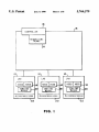
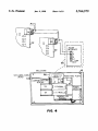
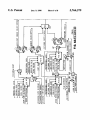
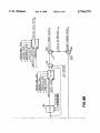
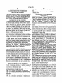
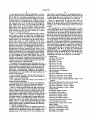
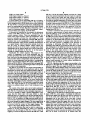
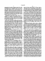
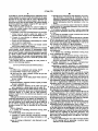
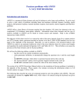
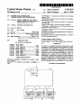
US005764579A
United States Patent [191
[11] Patent Number:
McMasters et a].
[45]
[54] SYSTEM FOR CONTROLLING
LABORATORIES WITH FUME HOODS
Date of Patent:
5,764,579
Jun. 9, 1998
“NETWORK” by American Auto-Matrix dated Spring/
[75] Inventors: David C. McMasters. Monroeville;
David M. Fisher. Pittsburgh; Bruce 1).
Arnold. Murrysville. all of Pa.
Summer 1989.
“SOLO/PX Hood/Lab Control” by American Auto-Matrix
dated about Jan. 1989.
“Face Velocity Control Systems" brochure by Anemostat.
copyright 1984.
[73] Assignee: American Auto-Matrix, Inc.
“Yamato Clean Benche” product description brochure.
“Envirotrak—A Laboratory Air Flow Control System from
[21] Appl. No.: 591,541
Anemosta ” dated Aug. 1985.
[22] Filed:
‘Total Lab Control for the 90's TLC-90" by Anemostat.
copyrighted in 1988.
Oct. 1, 1990
[51] Int. Cl.6
[52] US. Cl.
[58]
B08B 15/02
364/131; 454/59; 454/61;
454/62; 4541340
Field of Search
.
364/131. 132.
364/133. 1538145415641. 62. 340
[56]
Attomey Agent, or Firm—Reed. Smith. Shaw & McClay
U.S. PATENT DOCUMENTS
4,557,184
4,706,553
4,741,257
4,773,311
5,090,303
5,090,304
5,092,227
Primary Examiner-Reba I. Elmore
Assistant Examiner-Thomas E. Brown
References Cited
4,040,042
4,528,898
4,160,407
Information Disclosure Statement/Declaration of Linda Diss
and attachments thereto.
Information Disclosure Statement/Declaration of Richard
Fish and attachments thereto.
[57]
8/1977 Mayer.
7/1985
7/1979 Duyin
12/1985
11/1987
5/1988
9/1988
2/1992
2/1992
454/61
454/61
454/61
454/59
454/56
454/58
454/59
454/59
3/1992
UI'HER PUBLICATIONS
“SOLO/FX. Preliminary Production Description” dated
Nov. 14, 1988.
ABSTRACT
A system for controlling laboratories having fume hoods
comprising a network along which information is carried.
The system is also comprised of a controller in contact with
the network for receiving information from and providing
information to the network. Additionally. the system is
comprised of means for sensing a laboratory‘s state. The
sensing means is disposed in each laboratory. There is
additionally a microprocessor disposed in each laboratory
for receiving information concerning the laboratory from the
respective sensing means and the controller in order to
maintain the laboratory in a predetermined state. and to
provide information about the laboratory to the controller.
“SOLO/PX” by American Auto-Matrix, copyrighted in
1989.
54 Claims, 8 Drawing Sheets
1)8
[l6
CONYRGLLER
Rtnursnus
MEANS
E4
121
I21
LAB
121
Lat
LAB
man mm
MICROPRDCESSUR
Tea
HICRUPRQCESSUR
(22
% 20
HICROPRUCESSOR
\zz
US. Patent
0 Jun. 9, 1998
Sheet 1 008
5,764,579
‘)8
[l6
CONTROLLER
REQUESTING
MEANS
i
24
LAB
HOOD
LAB
H00!)
$500100
MEANS
,4
20
-
MICRUPROCESSOR
~
LAB
H000
0000M”,
H000
ssnsme 05020‘
H0011 ~44
SENSI 0N.
0500s
MEANS
MICROPROCESSUR
MICROPROCESSUR
T22
(22
H6. l
‘
2°
122
US. Patent
Jun. 9, 1998
Sheet 2 of 8
5,764,579
FUHE
FIG-2
r82
NICROPROCESSOR
FIG. 5
US. Patent
Jun. 9, 1998
5,764,579
Sheet 3 of 8
3x
A
E\bw\%woEZw,235;
E23;u
m
=.\
¢
INN
3,sump2a!5:?
kw?x
\
0. -“
how
5mwvwe
55%?\ss
FNE32"nmu
US. Patent
Jun. 9, 1998
Sheet 4 of 8
U
6ND
/
/_ .. _ _._ ...\
OA
‘ ‘
I
OB
l
1
0c
22
OD
ENCLOSURE
SHEILDED CABLE °
JACKET ca _
5,764,579
4/
’
:
Ir
I
I
i
[A
1
$2)1
I
I
1’
[l8
o
82v
GNP/C1
M ‘HI‘1-,.M0BULE‘) MOUNTING PLATE
conmumcmou I
WIRING
I
‘
l_]
.0
1]
., d-
g
m
‘1/0 MODULE‘
TM
‘1/0 MODULE‘
PWER
supmr?
:—a
FOUNDATI H
‘II
O
_
D
U
H
US. Patent
Jun. 9, 1998
Sheet 6 of 8
5,764,579
b|
Z5wz:2o5)w
4
2.S3g8u.85
45:2%o1:65
,H
Eézi3onaml21:3 : :WZ3EQ m5osm:d2315:M
2:02
.1
mum;
533.2:82:A,255 :
Pil
E2:35; $5 5“ 53a:mw
vHz;I.397E 352:
m2
wréuw
mm.03.
US. Patent
Jun. 9, 1998
Sheet 8 of 8
5,764,579
B = 1 f A
C = A ‘ B
PID
DELAY
E = MAXIMUM OF A, B,
E. 0R D
FIG. 8
5,764,579
1
2
SYSTEM FOR CONTROLLING
LABORATORIES WITH FUME HOODS
FIG. 7 is a schematic representation of a hood control
circuit.
FIG. 8 is a key. with respect to elements of FIGS. 6 and
FIELD OF THE INVENTION
7. de?ning them.
The present invention is related to systems for controlling
laboratories with fume hoods. More speci?cally. the present
DESCRIPTION OF THE PREFERRED
EMBODIMENT
Referring now to the drawings wherein like reference
numerals refer to similar or identical parts throughout the
several views. and more speci?cally to FIG. 1 thereof. there
is shown a schematic representation of a system 10 for
invention is related to a system for controlling laboratories
with fume hoods using a network to communicate with a
remote controller to control the state of the laboratory.
BACKGROUND OF THE INVENTION
Laboratories wherein dangerous experiments or processes
are performed require protections for the workers and the
experiments in the laboratory. One very common protection
controlling laboratories 12 having fume hoods 14. The
system 10 is comprised of a network 16 along which
information is carried. Preferably. the network 16 operates in
the half-duplex mode. for instance. with a two-wire RS485
network.
The system 10 is also comprised of a controller 18 in
contact with the network 16 for receiving information from
found in laboratories are fume hoods in which chemical
reactions are conducted. The fume hoods have air drawn out
of them thus essentially preventing any toxic fumes from
escaping the fume hood into the laboratory and threatening
the operators. The velocity of air drawn through the fume
hood sash is controlled to a value high enough to maintain
safety for the operator and low enough to provide non
turbulent air for the experiment of process.
An additional protection that can be provided is to main
tain the static pressure in the laboratory at a lower or higher
pressure than the pressure in the surrounding corridors of the
building. A lower pressure would prevent contaminants from
exiting the laboratory in the case of an accident.
A higier pressure would prevent contaminants from
entering the laboratory. as is the case in a clean room. Also.
and providing information to the network 16. Preferably. the
controller 18 includes means 24 for requesting information
from each microprocessor 22 about its condition. Preferably.
the requesting means 24 requests information from each
microprocessor 22 one at a time.
25
Additionally. the system 10 is comprised of means 20 for
sensing a laboratory's 12 state. The state of the laboratory is
de?ned as. at least. the static pressure and the supply/exhaust
differential of the laboratory 12. and also the face velocity of
the fume hood 14 in the laboratory. The sensing means 20 is
disposed in each laboratory 12. The sensing means 20
preferably includes a static pressure sensor 26. a supply/
exhaust differential sensor 28 and a face velocity sensor 30
disposed in each laboratory 12. as shown in FIG. 2. FIG. 2
is a schematic representation of the laboratory 12. There can
control of the laboratory climate is required both for opera
tor comfort and for certain experiments or processes where
strict temperature and humidity control are necessary.
also be included a temperature sensor 32.
There are many schemes and apparatuses that provide
such control and protection to laboratories. However. 35 There is also a microprocessor 22 disposed in each
laboratory 12 for receiving information concu-ning the labo
heretofore. there have been no systems that provide for
ratory 12 from the respective sensing means 20 and the
integrated direct digital control of laboratories.
controller 18 in order to maintain the laboratory 12 at a
SUMMARY OF THE INVENTION
predetermined state. and to provide information about the
laboratory 12 to the controller 18. Preferably. the controller
18 and the microprocessors 22 maintain the respective
The present invention pertains to a system for controlling
laboratories having fume hoods. The system is comprised of
a network along which information is carried. The system is
also comprised of a controller in contact with the network
for receiving information from and providing information to
the network. Additionally. the system is comprised of means 45
for sensing a laboratory's state. The sensing means is
laboratory 12 in the predetermined state by maintaining their
respective static pressure and supply/exhaust differential as
well as the face velocity of the hoods 14 of a given
laboratory 12.
The controller 18 and mitroprocessors 22 preferably
disposed in each laboratory. There is additionally a micro
opaate in a master slave relationship with the controller 18
processor disposed in each laboratory for receiving infor
mation concerning the laboratory from the respective sens
The master initiates all communications by sending mes
ing means and the controller in order to maintain the
being the master and the microprocessor 22 being the slave.
50
sages. Messages are composed. for instance. of data bytes
transmitted serially using standard asynchronous data
laboratory in a predetermined state. and to provide infor
mation about the laboratory to the controller.
frames. These data frames can consist of one start bit. eight
data hits. no parity bit. and one stop bit.
BRIEF DESCRIPTION OF THE DRAWINGS
In the accompanying drawings, the preferred embodi
The master and each slave share the same network 16 for
55
each slave must be able to enable/disable their transmitters
(not shown). so as not to interfere with other slaves’ trans
missions. The transmitter enable/disable should be con
trolled such that the carrier enable is switched off concur
ments of the invention and preferred methods of practicing
the invention are illustrated in which:
FIG. 1 is a schematic representation of a system for
controlling laboratories having fume hoods.
rently with the end of the final stop bit of any transmission.
The master arbitrates when a given slave may respond with
the simple rule that a slave only transmits in response to a
FIG. 2 is a schematic representation of a laboratory.
FIG. 3 is a schematic representation of a microprocessor.
FIG. 4 is a schematic representation of the network
message uniquely directed to it. See PUP guidelines (A
configuration.
FIG. 5 is a schematic representation of a module.
FIG. 6 is a schematic representation of the laboratory
control
transmitting and receiving (half-duplex). The master and
65
document entitled “PUP Protocol Guidelines" is available
from American Auto-Matrix. Inc. Please contact the PUP
Protocol Committee and request Version 6.) for an example
of a protocol that can be used in ?re system.
5,764,579
3
4
In the operation of the preferred embodiment. a micro
processor 22 is disposed in each laboratory 12. as shown in
FIG. 3. FIG. 3 is a schematic representation of the micro
processor 22. The microprocessor 22 is comprised of a fuse
32 which protects the microprocessor 22 from electrical
cates that the microprocessor 22 is operating properly. A
third led 74. when on. indicates that the microprocessor 22
is transmitting data to the controller 18. A fourth led 76
indicates when the microprocessor 22 is receiving data.
There is a jumper block 78 with two pins. When the
jumper block 78 is installed. a termination resister is posi
tioned for the RS485 network 16. The microprocessor 22
connects to the network 16 through the network connection
port 80.
overload. There is a transformer 34 for converting current
and voltage provided to the microprocessor 22 through the
power input port 36. There is a ?rst switch block 38 with
eight switches used to select thermister support for eight
analog inputs. When any given switch is on (moved to the
right). it operates as a thermister and when any given switch
is o? (moved to the left). the switch operates in a normal
mode. as is well known in the art.
There is a second switch block 40 with eight switches
used to select a current or voltage mode for analog inputs
The controller 18. as shown in FIG. 4 which is a sche
matic representation of the network con?guration. includes
a module 82. FIG. 5 shows a module 82 and is a schematic
representation of the module 82. The module 82 includes a
module processor 84 for providing the proper instructions to
the various laboratory 12 microprocessor 22 via the network
one through eight. When the switch is off. the voltage mode
16. as well as for receiving information to better maintain
is utilized and when the switch is on. the current mode is
the overall system 10 from the various microprocessors 22
utilized. There is an analog input port 42 which receives
and the laboratories 12. The module 82 also includes a reset
button 86. a system task led 88 and a communications led
89. The reset button 86 is used to reset the communication
analog input wiring. i.e.. high resolution (12-bit) input
devices such as ?ow sensors. velocity sensors. the static
pressure sensor. and the discharge air temperature sensor are
module 82 without resetting the entire STAR controller 18.
The system task LED 88 is lit to indicate that the commu
hardwired (connected) to the analog input port 42 (TB3). A
processor 44 processes the information received by the
microprocessor from the network 16 and sensors in the
laboratory 12 and also provides information concerning the
respective laboratory 12 to the network 16. A universal input
25
90 which connect the module 82 to the dual RS485 com
wiring input port 46 receives analog/digital input wiring.
i.e.. low resolution (8-bit) and digital input devices such as
munications network 16. In general. for the preferred
embodiment. the inputs and outputs are the following:
the room temperature sensor. sash position sensors, the
humidity sensor. and the emergency contacts are hm'dwired
Analog Inputs
A11 Space Static Pressure
A12 Supply Air Flow
to input port 46 (T31). A third switch block 48 with eight
switches is used to select therrnister support for the universal
input port 46 inputs one through eight.
The memory for the microprocessor 22 includes an execu
tive eprom 50. a nonvolatile ram52. an application eprom 54 35
and an expansion eprom/ram 56. The executive eprom 50
contains the basic operating routines of the microprocessor.
Input/output. communications. diagnostics. and initializa
The application eprom 54 contains the laboratory!‘
fnmehood control algorithms.
The expansion eprom/ram 56 is used for extra application
A13
A14
A15
A16
A17
Exhaust Air Flow
Hood A Air Flow
Hood B Air Flow
Hood A Face Velocity
Hood B Face Velocity
A18 Discharge Air Temperature
Universal Inputs
U11 Room Temperature--8-bit Analog
tion routines as well as the utility routines for the application
which include but are not limited to the math functions and
the PID control routines.
The non-volatile ram 52 is used for work space for the
executive and the application as well as for storage of
attributes and control parameters.
nication module 82 task is currently being serviced. The
communication LED 89 is lit when the communication
module 82 is idle. i.e. not transmitting. There are also ports
U12 Hood A Sash Area—-?»bit Analog
U13 Hood B Sash Area—8-bit Analog
45
U14 External Supply Damper/Humidity Input—8-bit
Analog
U15 External Exhaust Plow 1nput--8-bit Analog
algorithm storage or for extra non-volatile ram storage. In
U16 Space Emergency Contact—Digital
the present SOLO/PX con?guration. this site is unused.
U17 Hood A Emergency Contact—Digital
U18 Hood B Emergency Contact—Digital
There is a fourth switch block 58 with eight switches that
can be used as determined for a given situation. The digital
(binary) output port 60 is used to connect devices to the
microprocessor for annunciating alarm conditions and for
general purpose digital outputs. A ?fth switch block 62 with
Analog Outputs
A01 Supply Damper Position
A02 Reheat Valve Position
55
eight switches is used to select a current or a voltage mode
for analog outputs ?ve through eight of analog output port
66. There is a three-volt lithium smart battery 64 used to
maintain the data in the ram 52 in the event of a power
failure. There is a sixth switch block 68 that has eight
switches that are used for analog outputs one through four of
analog output port 66 to determine whether they should be
in a current or voltage mode.
A03 Exhaust Damper Position
A04 Hood A Damper Position
A05 Hood B Damper Position
A06 Auxiliary Reheat Valve Position
A07 Total Exhaust Air Flow
A08 Humidity Cooling Valve Position
Digital Outputs
D01 Space Emergency Output
A ?rst led 70 indicates whether the application eprom 54
is installed in the microprocessor 22. If the led 70 is off. it 65
indicates that the application eprom 54 is installed in the
D02 Hood A Emergency Output
D03 Hood B Emergency Output
microprocessor 22. A second led 72. when ?ashing. indi
D04 High Limit Output
5,764,579
6
5
DOS bow Limit Output
PID No. 3 of the lab control diagram such that its 0 input
D06 Digital Output 6-Unused
D07 Digital Output 7-—Unused
D08 Digital Output 8-—Unused
passes the manual temperature set point signal (as opposed
to the 1 input of the switch 115 with respect to the ?rst
procedure which passes the error signal from PID No. 2). By
choosing the manual temperature set point input. the signal
A given module can be networked with up to 32 micro
processors 22 in series as shown in FIG. 4. The module 82
provided by PD No. 2 is eliminated and a ?xed temperature
set point is then provided to the PID No. 3. The subsequent
can be integrated into a STAR which serves as the controller
18. The STAR is a microprocessor based. multitasking ?eld
operation of the second procedure for controlling tempera
panel for monitoring and controlling devices which include
ture in the room is the same as the operation of the ?rst
the communication module 82. More information can be
found in a document entitled “STAR User Manual” Ameri
can Auto-Matrix part number 1E-04-00-0054.
procedure described above for controlling the temperature
starting from PID No. 3.
In order to control the static pressure and the delta ?ow in
the room. a space pressure set point signal is provided to
input SP of PD No. 1. The actual space pressure is provided
to input MV of PID No. 1. An error signal corresponding to
the di?’erence in these signals is then produced from PID No.
A laboratory is controlled by. for instance. the laboratory
control circuit 100 as shown in FIG. 6. A discussion of its
control sequence follows. Thm'e are preferably four ele
ments of the control sequence. These are temperature. static
pressure. humidity and delta ?ow with respect to a room
1 and is the delta ?ow set point signal provided to input SP
under the control of the laboratory controller 100. The four
variables that can be manipulated in order to obtain the
of PD) No. 4. (Recall that static pressure and delta ?ow are
related since static pressure is constant when delta ?ow is
zero; and static pressure is changing in the direction of
increasing or decreasing delta ?ow when delta ?ow is
desired temperature. static pressure. humidity and delta ?ow
is a supply damper. which controls the amount of air ?ow
into the room; an exhaust damper. which controls the
changing). Thus. PID No. 1 provides the delta ?ow set point
dehumidi?es the air; and the reheat valve. which controls the
amount of heat provided to the ?ow of air that passes
that corresponds to the di?'erence between the actual static
pressure in the room and the desired static pressure in the
room. If the actual static pressure is the desired static
througr the supply damper into the room.
pressure. then the delta ?ow set point signal is essentially
Speci?cally. the control sequence with respect to the
control of temperature in the room preferably has two
possible procedures that can be used to introduce additional
zero. If the actual static pressure is di?‘erent than the desired
amount of air ?ow out of the room; a cooling valve which
static pressure. then the delta ?ow set point signal corre
sponds to this di?erence. The actual delta ?ow signal in the
room is provided to the MV input of PID No. 4. Optionally.
PID No. 1 can be used to directly control the supply and
heat. less heat or the same amount of heat into the room. The
?rst procedure utilizes a temperature sensor 32 which deter
mines the room temperature and provides a corresponding
signal to the measured variable (MV) input of PID No. 2. as
exhaust (static pressure) in a room without utilizing ?ow
shown in FIG. 6. PID No. 2 also receives in its set point (SP)
input a room temperature set point signal which corresponds
35
to a desired room temperature.
sensors by way of switch 117.
PID No. 4 produces an error signal corresponding to the
ditference in the delta ?ow set point signal and the actual
delta ?ow signal. This error signal from PlD No. 4 is then
The P113 No. 2 provides an error signal corresponding to
provided to the exhaust damper output. The exhaust damper
the difference between the room temperature and the room
is accordingly moved in response to the command placed on
it from the signal of PID No. 4. The error signal from PID
No. 4 is also provided to the maximum switch 110 to which
the error signal PlD No. 3 is also provided.
The maximum switch 110 allows the greatest of four
temperature set point. This error signal provided by P1!) No.
2 is then used as the temperature set point input which is
provided to the SP input of PID No. 3. The PID No. 3 also
receives a discharge temperature signal through its MV input
signals (auxiliary reheat. reheat. static pressure and extm'nal
which corresponds to the temperature of the air entering the
room through the supply damper. PID No. 3 then provides
an error signal that corresponds to the error between the
supply) to pass to the supply damper output. It is the greatest
45
discharge temperature and the temperature set point. This
of these four signals which controls the supply damper. This
way. for instance. if more heat is to be provided to the room
in order to increase the temperature of the room. then the
error signal from PlD No. 3 is then used to control the reheat
valve. The output of P11) No. 2 can optionally be used to
control an auxiliary reheat valve if one is present in the
supply damper will also increase the ?ow of heated air into
the room. If. the signal from PID No. 4 is greatest than the
room.
50 signal from PID No. 3 due to. for instance. the static
The control of the reheat valve can be better understood
pressure. or the delta ?ow being increased. then the supply
damper will provide a greater ?ow of air to the room in order
with the following examples. If the error signal, for instance.
to increase the static pressure or the delta ?ow.
from PID No. 3 indicates that the discharge temperature is
With respect to the delta ?ow signal provided to the MV
not yet hot enough to obtain a desired temperature in the
room. then the reheat valve will open further to allow 55 input of PID No. 4. the signal is essentially the di?'erence
between the supply ?ow into the room and the exhaust ?ow
additional heat to be supplied to the air ?ow passing into the
room though the supply damper. If the error signal from
PID No. 3 is. for instance, too high. then the reheat valve is
out of the room. The exhaust ?ow out of the room is
determined one of two ways. In the event that a sensor
caused to allow less heat to be provided to the ?ow of air into
determines the overall exhaust ?ow from a room. then this
value is subtracted from the supply ?ow into the room at
subtractor 120 to yield the delta ?ow of the room. If the
the room through the supply damper. The error signal from
PID No. 3 is also provided to a maximum switch 110 which
is involved with the control of the supply damper. The
control of the supply damper will be discussed below.
The second procedure that can be used to control tem
perature is for the temperature set point to be manually
inputted into the SP input of PID No. 3. This is done by
toggling a switch 115 disposed between the PID No. 2 and
exhaust ?ow sensor is disposed such that it only determines
exhaust ?ow out of the room but does not determine the
exhaust ?ow out of the room from a hood A and a hood B.
65
then the total exhaust ?ow is determined by adding the
exhaust ?ow out of the room plus the addition of the exhaust
?ow out of hood A and hood B at summer 125. The
5 .764,579
7
8
aforementioned is reduced to practice in part with a switch
sash area for ?ow control (see FIG. 7). If face velocity is
chosen as the basis for measurement. then the 1 input of
130 toggled to allow the appropriate signal to pass. If the
switch 200 receives the velocity signal corresponding to the
face velocity of the hood. This face velocity signal is passed
sensor determines the overall ?ow out of a room. then the
switch 130 is toggled to allow a zero input signal to pass
through the 1 input of the switch 130. If the exhaust sensor
is disposed such that only the exhaust of the room less the
exhaust out of hood A and hood B is sensed. then the switch
130 is toggled such that the sum of the exhaust out of hood
A and hood B (accomplished with summer 135) is passed
through the input of the switch 130 to be added at summer
125 to the exhaust ?ow from the room.
Alternatively. the delta ?ow set point signal can be
manually set by toggling a switch 140 between PID No. l
and PID No. 4 to only allow a manual ?ow set point signal
to pass through the switches input (as opposed to allowing
15
the delta ?ow set point signal of PID No. 1 to pass through
the input of the switch 140).
In the event it is desired to manually control the exhaust
damper and the supply damper such that they are fully open
or fully shut. respectively. by properly toggling switch 150
through switch 200 to the MV input of PID No. 5 and PID
No. 6 (PID No. 5 controls a ?rst hood and PID No. 6 controls
a second hood). Additionally. through switch 210’s one
input is received a face velocity set point signal which is
then passed through switch 210 to the set point SP input PID
No. 5 and PID No. 6. The face velocity signal received at
input MV is compared to the set point signal received at
input SP and an error correction signal is outputted from PID
No. 5 and PID No. 6 and provided to switch 220. If switch
220 is not toggled to an override position. then the signal
outputted from PID N0. 5 and PID No. 6 is then passed
directly to the exhaust damper of the hood positioning it to
be in a desired location. In the event that the override mode
20
and switch 160. respectively. a 100% open or 0% open
is toggled on switch 220. then the output signal from switch
220 causes the exhaust damper to take a fully opened
position and allow the maximum possible exhaust to be
obtained.
signal, respectively. is provided to the switches 1 inputs and
Alternatively. if the ?ow control is used as a basis to
is passed therethrough to open or close the exhaust and
supply dampers. respectively. In this manner. the room can
be quickly depleted of air. if. for instance. a ?re or toxic
chemical release occurs. If the switch 50 and switch 60 is
toggled such that the signal at their 0 inputs are passed
therethrough. then the signals from PID No. 4 or from the
maximum switch 10 is passed to the exhaust or supply
maintain the exhaust damper. then the 0 input of switch 200
receives the sensed ?ow through the exhaust This signal is
then passed directly through switch 200 to the MV input of
PID No. S and PID No. 6. Switch 210 passes through the
25
signal at its 0 input. This signal is the sash area of the hood
multiplied by the face velocity set point. This resulting
signal is provided to the SP input of the PID No. 5 and PID
damper. respectively.
No. 6.
Optionally. to maintain a minimum air ?ow into a room.
The set point signal provided by multiplying the face
which provides for a minimum number of air changes for a
velocity set point by the sash area is additionally fed to a PID
delay 230 as well as to a multiplier 240. At the multiplier
given time (per hour) in a room. the output signal from
switch 110 is received by both scaler 162 and switch 164 (if
240. the signal is multiplied by a feed forward gain that
it is desired not to maintain a minimum air ?ow. then switch 35 provides a course adjustment signal which is received by
summer 250. Summer 250 adds the course adjustment signal
164 is set to O and the output from switch 110 passes directly
from multiplier 240 to a feed forward offset signal. This
to switch 160). Scaler 162 receives a minimum and maxi
summed signal is provided to switch 266.
mum air ?ow range. Scaler 162 then scales the output signal
If the velocity mode is toggled. then a 0 output from
from switch 110 to be in an allowable air ?ow range. The
output signal from sealer 162 is then provided to the SP input
40
of PID No. 8. The MV input of PID No. 8 receives a supply
switch 260 is provided to the PID No. 5 and P11) No. 6. If
the sash mode is chosen. then the signal received from
?ow signal indicating the supply ?owing through the supply
summer 250 is passed to the FF input ofPID No. 5 and PID
No. 6. The feed forward o?’set signal is based on the
parameters of the system such as the duct con?guration and
provided to the supply damper.
The humidity control is accomplished by PID No. 7 45 hood size. The ultimate purpose of the feed forward gain and
damper and outputs a signal to switch 164 which is then
receiving through MV input the humidity sensed by a
feed forward oifset being provided to the set point signal in
the sash mode is to allow the exhaust damper to properly
humidity sensor in the room. The humidity set point is
predetermined and provided to the SP input. The output of
compensate for the situation where the sash area and thus the
PID No. 7 controls a cooling valve based on the level of
damper is suddenly changed. The exhaust damper lags in
humidity in the room. If the humidity is too high. then the
cooling valve is opened ftn'ther. This causes the room
temperature to drop thus causing the humidity in the room
to drop.
The control sequence with respect to the ?ow of air
through a hood 14 is based on. in general. coordinating the
sash area of the hood 14 with the hood exhaust damper
opening. When the sash area is increased. the damper
opening is also increased in order to remove the additional
volume of air that is provided to the hood (because of the
increased sash area) and thus maintain the desired face
velocity. When the sash area is decreased. the damper
opening is also decreased in order to prevent the smaller
volume of air through the smaller sash area from being
time in terms of how it compensates for this change in sash
drawn too quickly through the damper opening.
Consequently. the desired face velocity is again maintained.
The control sequence provides for control of either face
velocity for velocity control. or face velocity multiplied by
area. In order to eliminate or minimize the o?’shoot that the
exhaust damper experiences from the sudden change in the
sash area. the signal received by input FF causes the exhaust
damper to move to the desired course position. The PID N0.
$5
5 and PID No. 6 utilizing the inputs from input MV and
input SP then places the exhaust damper in an essentially
?ne adjustment until it arrives at a desired position.
The set point signal. arrived at by multiplying the face
velocity set point time to sash area in the sash mode is also
provided to PID delay 230. The PD) delay 23!! produces a
signal based on the time it takes the damper to achieve full
actuation (provided through the damper delay input to the
PH) and based on the maximum ?ow through the damper
when it is fully opened). This delay signal is provided to
65
switch 270 which. if the sash mode is being utilized. is then
provided directly to the hold input of PID No. 5 and PID No.
6. The signal received at the hold input prevents the PID No.
5,764,579
10
9
a microprocessor disposed in each laboratory for receiv
S and PID No. 6 from calculating the ?ne adjustment of the
exhaust damper for a period of time determined by the signal
provided at the hold input until the course adjustment has
had time to reposition the exhaust damper. After the time
period has passed. then the ?ne tuning of the exhaust damper
position is allowed to continue using the MV input and SP
input of P11) No. 5 and PID No. 6.
The control sequence provides for control of either face
ing information concerning the laboratory from the
respective sensing means and the controller in order to
maintain the laboratory in a predetermined state. and to
provide information about the laboratory to the con
troller.
2. A system as described in claim 1 wherein the controller
includes means for requesting information from each labo
ratory about its condition.
3. A system as described in claim 2 wherein requesting
velocity for velocity control or face velocity multiplied by
sash area for ?ow control.
means requests information from each microprocessor one
Accordingly. at least the following features are provided:
1. Fume hood air velocity control for safety of the
at a time.
4. A system as described in claim 3 wherein the network
operator and/or integrity of the experiment/process.
operates in the half-duplex mode.
2. Control of room pressure to maintain safety or to
5. A system as described in claim 4 wherein the controller
prevent contamination.
3. Control of room temperature and humidity for comfort
and for process requirements.
4. Integration of velocity. pressure and climate control
with a direct digital control system.
and the microprocessors maintains the respective laboratory
in the predetermined state by maintaining the respective
static pressure and supply/exhaust differential as well as the
face velocity of the hoods of a given laboratory.
6. A system as described in claim 5 wherein the sensing
which permits several methods of measurement which
means includes a static pressure sensor. a supply/exhaust
di?erential sensor. and a face velocity sensor disposed in
derive their input ?'om a universal input connected to some
type of sensor. usually a multi-turn potentiometer connected
7. A method for controlling laboratories having fume
The sash area of a fume hood is calculated from a formula
each laboratory.
to a drum or pulley which is directly attached to the sash. 25 hoods comprising the steps of:
sensing a state of each laboratory having a fume hood;
The formula takes into account several parameters which
providing information corresponding to the state of each
can be programmed by the user to model the speci?c fume
laboratory with a fume hood to a perspective micro
hood and sash system.
processor associated with each laboratory;
The formula used for calculating the sash position is
shown in the following equation:
providing information to a respective microprocessor
from a controller at a remote location; and
maintaining a respective laboratory in a predetermined
state with the microprocessor based on the information
received ?‘om the controller and the information cor
Where:
0A Offset Area-minimum sash opening. SQ Fl‘
GA Sash Width-width of sash opening. Fl‘
35
SR Pot Turns Per lO0%—-number of turns the post has
responding to the state of each laboratory.
8. A method as described in claim '7 wherein the sensing
step includes the steps of sensing a static pressure and a
from endstop to en'dstop
U1 Universal Input-S-bit analog input which measures
supply/exhaust di?’erential of the respective laboratory. and
simply be SD.
Although the invention has been described in detail in the
foregoing embodiments for the purpose of illustration. it is
microprocessor. and the step of providing the information by
a face velocity of a respective fume hood; and wherein the
step of providing information corresponding to the state of
the pot voltage
each laboratory includes information about the static pres
PI Pi—3.1416
sure and a supply/exhaust ditferential of the respective
SD Drum Diameter—diameter of drum or pulley to which
laboratory. and the face velocity of a respective fume hood.
the pot is attached. IN
V
9. A method as described in claim 8 including after the
ST Cable Thickness-thiclmess of the cable used if the
45 step of providing information to a respective
pot is attached to a drum which coils the cable. IN
microprocessor. there is the step of providing information to
This equation accounts for the added diameter of the drum
the controller by the respedive microprocessor.
caused by the coiled cable. In the case of a system with a pot
10. A method as described in claim 9 wherein the step of
connected direaly to a pulley. the ST. cable thickness,
providing information to the controller includes the step of
attribute would be set to 242-0 and the drum diameter would
50 requesting information by the controller from a
to be understood that such detail is solely for that purpose
and that variations can be made therein by those skilled in
the art without departing from the spirit and scope of the
invention except as it may be described by the following
claims.
What is claimed is:
l. A system for controlling laboratories having fume
hoods comprising:
a network along which information is carried;
a controller in contact with the network for receiving
information from and providing information to the
network;
means for sensing a laboratory‘s state disposed in each
laboratory;
the microprocessor to the controller only when the controller
requests the information from the microprocessor.
11. Amethod as described in claim 10 wherein the step of
55
requesting information includes the step of requesting the
information from the microprocessor. one at a time.
12. Apparatus for monitoring and controlling a fume hood
of the type which has an opening and at least one moveable
sash door adapted to at least partially cover the opening as
the fume hood sash door is moved, the fume hood having an
exhaust duct for expelling air and fumes therefrom. said
fume hood being of the type which has a ?lter housing and
?lter means for entrapping fumes and e?luents. said appa
ratus comprising:
means for determining the size of the uncovered portion
of the opening and for generating a position signal
indicative of the determined size;
5 ,764,579
11
12
means for measuring the ?ow of air through the fume
hood and generating a ?ow signal that is indicative of
said second emergency switching means providing an
emergency signal to said room controlling means and
to the fume hood controller means of at least some of
the fume hoods in response to a person actuating said
second switching means. said fume hood controller
means controlling the modulating means to increase the
?ow rate thereof to a predetermined maximum. said
room controlling means controlling the air supply to the
room to modulate the ?ow of air into the room whereby
the diiferential pressure in the room is within the range
of about 0.05 and 0.1 inches of water lower than a
reference pressure outside of the room, so that any
the ?ow of air therethrough;
modulating means for varying the ?ow of air through the
fume hood responsive to a control signal being received
from a controller means;
means for measuring the dilferential pressure across the
?lter housing and providing an electrical differential
pressure signal that is proportional to the measured
di?‘erential pressure; and
controller means responsive to said position signal and
said actual ?ow signal for controlling the ?ow modu
lating means to control the flow of air through the fume
hood. said controller means generating a high ?lter
loading signal responsive to said ditferential pressure
signal exceeding a predetermined value.
outwardly opening door can be opened by a person
inside the room and the di?erential pressure will not
15
normally force any inwardly opening door open.
19. A system as de?ned in claim 17 wherein said prede
termined emergency ?ow rate is the maximum ?ow rate.
20. A system as de?ned in claim 17 wherein said fume
13. Apparatus as de?ned in claim 12 further comprising
means for generating a warning indication in response to
hood controller means operates to provide said predeter
said high ?lter loading signal being generated.
mined emergency ?ow rate at a high ?ow rate for a prede
termined time and then reduce the ?ow rate thereafter.
14. Apparatus as defined in claim 13 wherein said warning
indication generating means comprises a means for provid
21. A system for controlling the differential pressure
ing a visual indication.
within a room such as a laboratory or the like of the type
15. Apparatus as de?ned in claim 13 wherein said warning
which has one or more exit doors which can open either
indication generating means comprises a means for provid
25 inwardly or outwardly of the room. the room being located
ing an audible indication.
in a building having a building heating and air conditioning
16. Apparatus as de?ned in claim 12 wherein said con
apparatus, including a central monitoring station. the room
troller means is adapted to increase the ?ow of air through
having
a plurality of fume hoods located within it. the fume
said fume hood to compensate for said ?lter loading in
hoods being of the type which have at least one moveable
response to receiving said high ?lter loading signal.
sash door adapted to at least partially cover the opening as
17. A system for controlling the di?’erential pressure
the fume hood sash door is moved. each of the fume hoods
within a room such as a laboratory or the like of the type
having an exhaust duct that is in communication with an
which has one or more exit doors which can open either
exhaust apparatus for expelling air and fumes from the
room said comprising:
inwardly or outwardly of the room. the room being located
in a building having a building heating and air conditioning
apparatus. including a central monitoring station. the room
having a plurality of fume hoods located within it. the fume
hoods being of the type which have at least one moveable
35
modulating means associated with each fume hood and
its associated exhaust duct to provide the greater of the
?ow required to maintain a predetermined minimum
sash door adapted to at least partially cover the opening as
?ow through said exhaust duct or to maintain a desired
the fume hood sash door is moved. each of the fume hoods
having an exhaust duct that is in communication with an
exhaust apparatus for expelling air and fume from the room.
face velocity through the uncovered portion of the
opening;
said system comprising:
hood and adapted to control the air ?ow through the
fume hood;
a ?rst emergency switching means located adjacent each
fume hood adapted to be activated by a person in the
modulating means associated with each fume hood and
its associated exhaust duct to provide the greater of the
?ow required to maintain a predetermined minimum
event of a chemical spill or the like. said switching
means providing a signal to said fume hood controller
?ow through said exhaust duct or to maintain a desired
face velocity through the uncovered portion of the
opening;
50
means to control the ?ow modulating means to achieve
a predetermined emergency ?ow rate;
a second emergency switching means located outside of
the room;
55
a second emergency switching means located outside of
the room;
room controlling means for controlling at least the volume 65
of air that is supplied to the room from the heating and
air conditioning apparatus of the building;
.
said ?ow modulating means associated with each fume
a fume hood controller means for controlling a ?ow
said ?ow modulating means associated with each fume
hood and adapted to control the air ?ow through the
fume hood;
a ?rst emergency switching means located adjacent each
fume hood adapted to be activated by a person in the
event of a chemical spill or the like. said switching
means providing a signal to said fume hood controller
means to control the ?ow modulating means to achieve
a predetermined emergency ?ow rate and providing a
signal to the central monitoring station indicating an
emergency condition.
18. A system as de?ned in claim 17 further including:
a fume hood controller means for controlling a flow
room controlling means for controlling at least the volume
of air that is supplied to the room from the heating and
air conditioning apparatus of the building;
said second emergency switching means providing an
emergency signal to said room controlling means and
to the fume hood controller means of at least some of
the fume hoods in response to a person actuating said
second switching means. said fume hood controller
means controlling the modulating means to increase the
?ow rate thereof to a predetermined maximum. said
room controlling means controlling the air supply to the
room to modulate the ?ow of air into the room whereby
the diiferential pressure in the room is within the range
of about 0.05 and 0.1 inches of water lower than a
5,764,579
13
14
outwardly opening door can be opened by a person
resistance means located adjacent the sash doors adapted to
be contacted at different positions along its length by actua
inside the room and the di?ierential pressure will not
tor means associated with each sash door as each sash door
reference pressure outside of the room. so that any
normally force any inwardly opening door open.
is horizontally moved. said position signals being generated
22. A system as de?ned in claim 21 wherein said prede
termined emergency ?ow rate is the maximum ?ow rate.
23. A system as de?ned in claim 21 wherein said fume
hood controller means operates to provide said predeter
mined emergency ?ow rate at a high ?ow rate for a prede
termined time and then reduce the flow rate thereafter.
by said detecting means comprising voltage levels that are
indicative of the horizontal positions of each sash door.
27. Apparatus as de?ned in claim 26 wherein said plu
rality of sash doors are mounted in a frame means that is
moveable in a vertical direction. said detecting means fur
ther comprising a second elongated resistance means located
adjacent the frame means adapted to be contacted at different
24. Apparatus for controlling the air ?ow through a fume
positions along its length by actuator means associated with
hood to nmintain a predetermined average face velocity
through an uncovered portion of an opening of a fume hood
of the type which has at least one moveable sash door
adapted to cover the opening as the fume hood sash door is
moved. the fume hood being in communication with an
exhaust duct for expelling air and fumes ?'om the fume
said frame means as said frame means is vertically moved.
said position signals being generated by said detecting
15
hood said apparatus comprising:
means for detecting the position of each moveable sash
door and generating a position signal that is indicative
of the sash door position;
means responsive to said position signals for calculating
the size of the uncovered portion of the opening;
means for measuring the actual ?ow of air through the
exhaust duct and generating an actual ?ow signal that
is indicative of the actual ?ow of air through the
25
means also comprising voltage levels that are indicative of
the vertical position of each sash door.
28. Apparatus as de?ned in claim 24 wherein said modu
lating means comprises a motor driven blower means
wherein said motor is controlled by a motor in order to vary
the exhaust air flow in the duct.
29. Apparatus as de?ned in claim 24 wherein said modu
lating means comprises a damper means located in the
exhaust duct and actuating means for varying the position of
the damper means to thereby vary the ?ow of air through the
exhaust duct.
30. Apparatus as de?ned in claim 24 wherein said air ?ow
measuring means comprises a flow sensor.
31. Apparatus as de?ned in claim 24 wherein said con
troller means determines three distinct factors of said error
exhaust duct;
modulating means for varying the ?ow of air through the
exhaust duct responsive to a control signal being
signal from said successive samples and sums the said
factors to generate said error signal. said factors comprising
a proportional action factor. an integral action factor and a
derivative action factor.
32. Apparatus as de?ned in claim 31 wherein said integral
action factor at any given time is directly proportional to the
received from a controller means;
controller means responsive to said position signals and
said actual ?ow signal for controlling the flow modu
lating means to generate the greater of a predetermined
minimum ?ow rate signal value or a desired ?ow rate 35 integral action factor calculated from the immediately prior
signal value as a function of the calculated size of the
sample multiplied by a loop cycle time. plus any error
measured by the present sample.
uncovered portion. said desired ?ow rate signal corre
sponding to a ?ow rate that is su?icient to maintain the
33. Apparatus as de?ned in claim 31 wherein said deriva
predetermined average face velocity through the
tive action factor at any given time is directly proportional
uncovered portion of the opening, said controller
means comparing said desired ?ow rate signal and said
actual ?ow rate signal and generating an error signal
indicative of any error that exists by taking a plurality
to the difference between any error determined from the
immediately prior sample and the current sample divided by
a loop cycle
34. Apparatus as defined in claim 31 wherein said pro
portional action factor at any given time is directly propor
of successive measurement samples of said actual ?ow
rate. determining at least two distinct factors of said
tional to any error determined from the current sample.
error signal from said successive samples and summing
35. Apparatus as de?ned in claim 31 wherein said modu
lating means comprises a motor driven blower means
wherein said motor is controlled by a motor controller
adapted to vary the speed of the motor. said controller means
the said factors to generate said error signal. said
controller means generating and outputting a control
signal to said modulating means for selectively reduc
ing said error signal to a predetermined minimum value
when said actual ?ow rate signal exceeds said prede
termined minimum ?ow rate signal value or providing
a predetermined minimum ?ow rate.
25. Apparams as de?ned in claim 24 wherein the fume
50
generating a feed forward control signal for said modulating
means and inhibiting any error signal generation in response
to a sash door being moved. said feed forward control signal
predicting the actual ?ow rate of air through the exhaust duct
as a function of the calculated size of the uncovered portion.
said controller means thereafter causing the inhibiting of any
hood has one sash door that is moveable in a vertical 55
direction to seledively cover and uncover the opening, said
error signal generation.
detecting means comprising an elongated resistance means
36. Apparatus as de?ned in claim 35 wherein said feed
located adjacent the sash door adapted to be contacted at
different positions along its length by actuator means asso
ciated with said sash door as the door is moved vertically,
said position signal being generated by said detecting means
forward control signal at any given time comprises an
intercept value plus a slope value multiplied by a predeter
mined set ?ow value.
37. Apparatus as de?ned in claim 24 further including an
operator panel adapted to be mounted on the fume hood in
comprising a voltage level that is indicative of the position
of said sash door.
position to be observed by a person. said operator panel
26. Apparatus as de?ned in claim 24 wherein the fume
including display means for displaying the average face
hood has a plurality of sash doors that are moveable in at 65 velocity being calculated for the associated fume hood. and
least a horizontal direction to selectively cover and uncover
for displaying other status information relative to the opera
the opening. said detecting means comprising an elongated
tion of the apparatus.
5 ,764,579
16
15
38. Apparatus as de?ned in claim 37 wherein said opera
tor panel includes means for placing said controller in one of
to said modulating means associated with each fume
hood for selectively reducing said error signal to a
two modes of operation. one mode being a day mode and the
other a night mode. said controller means including memory
means for storing information relative to the operation of
said apparatus. said controller means being adapted to
receive separate predetermined average face velocity values
for each of said day and night modes.
39. Apparatus as de?ned in claim 38 wherein said opera
predetermined minimum value or maintaining a prede
termined minimum actual ?ow.
5
43. Apparatus as de?ned in claim 42 wherein said con
troller means determines three distinct factors of said error
signal from said successive samples and sums the said
factors to generate said error signal. said factors comprising
a proportional action factor. an integral action factor and a
derivative action factor.
tor panel includes connector means adapted to be connected
to a computer means of the type which has a keyboard. the
computer means being capable. when connected to the
44. Apparatus as de?ned in claim 42 wherein said integral
action factor at any given time is directly proportional to the
integral action factor calculated from the immediately prior
sample multiplied by a loop cycle time. plus any error
operator panel. of de?ning parameters and operating values
of the fume hood to which the apparatus is to control.
40. Apparatus as de?ned in claim 39 wherein said param
eters and operating values include the number of sash doors
and the possible movement of such sash doors. the physical
dimensions of the sash doors and of the opening of the fume
to the di?erence between any error determined from the
hood. the average face velocity for day and night modes.
immediately prior sample and the current sample divided by
measured by the present sample.
45. Apparatus as de?ned in claim 42 wherein said deriva
tive action factor at any given time is directly proportional
41. Apparatus as de?ned in claim 24 wherein said means 20 a loop cycle time.
46. Apparatus as de?ned in claim 42 wherein said pro
for calculating the size of the uncovered portion of the
portional action factor at any given time is directly propor
opening comprises computing means located within said
controller means.
42. Apparatus for controlling the air ?ow through a
plurality of fume hoods to maintain a predetermined average
face velocity through an uncovered portion of an opening of
each fume hood. each fume hood being of the type which has
tional to any error determined from the current sample.
47. Apparatus as de?ned in claim 42 wherein said modu
25 lating means comprises a damper means located in the
exhaust duct and actuating means for varying the position of
at least one moveable sash door adapted to selectively cover
the opening as the fume hood sash door is moved. each fume
hood in communication with an exhaust duct for expelling
air and fumes from each fume hood. the exhaust duds for
each fume hood being in communication with an exhaust
30
system. said apparatus comprising:
means associated with each fume hood for detecting the
position of each moveable sash door and generating a
generally every 200 milliseconds.
35
100 milliseconds.
51. Apparatus for controlling the air ?ow through a fume
hood to maintain a predetermined average face velocity
through an uncovered portion of an opening of a fume hood
of the type which has at least one moveable sash door
adapted to cover the opening as the fume hood sash door is
moved, the fume hood being in communication with an
exhaust duct for expelling air and fumes from the fume
the size of the uncovered portion of the opening of each
fume hood;
45
responsive to a control signal being received from a
50
controller means responsive to said position signals and
said actual ?ow signal for controlling the ?ow modu
lating means associated with each respective fume
55
exhaust duct;
modulating means for varying the ?ow of air through the
exhaust duct responsive to a control signal being
received from a controller means;
that is suficient to maintain the predetermined average
face velocity through the uncovered portion of the
controller means responsive to said position signals and
said actual ?ow signal for conn-olling the ?ow modu
opening of each fume hood. said controller means
comparing said desired ?ow rate signal and said actual
?ow rate signal for each fume hood and generating an
error signal indicative of any errors that exist by taking
a plurality of successive measurement samples of said
actual ?ow rate. determining at least two distinct fac
tors of said error signal from said successive samples
and summing the said factors to generate said error
signal. said controller means outputting a control signal
door and successively generating a position signal that
is indicative of the position of each sash door;
means responsive to said position signals for calculating
the size of the uncovered portion of the opening;
means for successively generating an actual ?ow signal
that is indicative of the actual ?ow of air through the
hood to generate a desired flow rate signal as a function
of the calculated size of the uncovered portion. said
desired ?ow rate signal corresponding to a ?ow rate
hood. said apparatus comprising:
means for detecting the position of each moveable sash
in communication with the respective fume hood
controller means;
50. Apparatus as de?ned in claim 43 wherein said con
troller means generates said control signal generally every
position signal that is indicative of the position of such
sash door;
means responsive to said position signals for calculating
means for measuring the actual ?ow of air through the
exhaust duct in communication with each fume hood
and generating an actual ?ow signal that is indicative of
the actual ?ow of air through the exhaust duct;
modulating means associated with each fume hood for
varying the ?ow of air through the exhaust duct that is
the damper means to thereby vary the ?ow of air through the
exhaust duct.
48. Apparatus as de?ned in claim 43 wherein said mea
surement samples are taken generally every 100 millisec
onds.
49. Apparatus as de?ned in claim 43 wherein position
detecting means operates to generate a position signals
65
lating means. said controller means either generating a
control signal value that maintains a predetermined
minimum ?ow rate or generating a desired ?ow rate
signal as a function of the calculated size of the
uncovered portion. said desired ?ow rate signal corre
sponding to a ?ow rate that is su?icient to maintain the
predetermined average face velocity through the
uncovered portion of the opening. said controller
1
5,764,579
a
17
means generally continuously comparing said desired
?ow rate signal with successive instantaneous sample
values of said actual ?ow signal and generating an error
signal having a magnitude that is directly proportional
18
52. Apparatus as de?ned in claim 51 wherein said mea
surement samples are taken generally every 100 millisec
onds.
53. Apparatus as de?ned in claim 51 wherein position
to the sum of any calculated integration error. any 5 detecting means operates to generate a position signals
calculated derivative error and any calculated proporgenerally every 200 milliseconds.
tional error. said controller means successively gener54. Apparatus as de?ned in claim 51 wherein said con
ating and outputting a control signal to said modulating
troller means generates said control signal generally every
means for reducing said error signal to a predetermined
100 milliseconds.
minimum value or maintaining said predetermined 10
minimum actual ?ow.
*
*
*
*
*