1
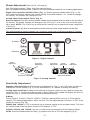
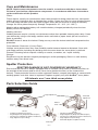
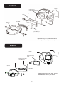
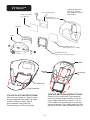
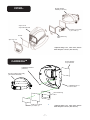
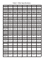
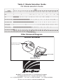
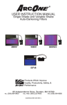
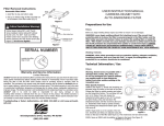
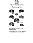
USER INSTRUCTION MANUAL
90X110 Auto-Darkening Filters
®
Products Which Improve
Quality, Productivity, Safety,
and Performance
ArcOne® is a Division of A.C.E. International Company
TEL:
85 Independence Drive, Taunton, MA 02780, USA
1+(508) 884-9600 •
TOLL FREE:
+1 800) 223-4685 •
FAX:
(508) 884-9666
PLEASE VISIT OUR WEbSITE: www.arc1weldsafe.com
M-EUROALTADF-2003 REV K
Table of Contents
Page
Preparations for Use........................................................................................1
Technical Information / Use .............................................................................1
Limitations of Use ............................................................................................3
Care and Maintenance ....................................................................................4
Spatter Protection............................................................................................4
Parts Selection Guide......................................................................................4
Filter Specifications .........................................................................................8
Significance of Markings:...............................................................................10
Shade Selection Guide ..................................................................................11
Filter Removal Diagram .................................................................................11
Preparations for Use
WARNING, materials which may come in contact with the wearer’s skin may cause an
allergic reaction to susceptible individuals.
Filters:
before you begin welding always inspect your filter to ensure it is not damaged. Check to see if
the filter protection plates (cover plates) are clean, clear, undamaged, and securely attached to
the helmet and covering the auto-darkening filter both front and rear. Make sure the fitler will turn
dark before using. Direct toward a bright light source or use a torch striker. Direct sunlight may
not darken the filter.
WARNING, never begin welding without first checking to see if the correct front and rear
protection plates are in place (See Part Selection Guide section for part numbers). Failure
to protect the welding filter may cause damage and become a safety hazard should the
UV/IR protection be compromised from spatter or cracks from impact. DAMAGE CAUSED
BY ABUSE SUCH AS EXCESSIVE TEMPERATURES, CRACKS FROM IMPACT, AND
PITTING FROM SPATTER CAUSED BY POOR MAINTENANCE WILL VOID WARRANTY.
Not for use in overhead welding.
WARNING, toughened mineral filter oculars shall only be used in conjunction with a
suitable backing ocular.
Welding Helmets:
before you begin welding make sure there is no damage to the helmet shell including, but not
limited to, cracks, holes, and melting. Ensure that the springs holding the filter are not broken or
corroded. Do not use the helmet if any of these conditions exist and contact your distributor for
replacement parts. Use only replacement components as specified for each welding helmet in
accordance with this user manual.
Adjust headgear for comfort and proper sight-line through the filter (see Parts Selection Guide).
WARNING, other safety precautions such as protective clothing, adequate ventilation,
breathing protection (e.g. powered air purifying respirator), fire extinguisher, and
protection for co-workers, should also be considered. Consult an Industrial Hygenist to
ensure adequate protection is being provided.
Technical Information / Use
Filters:
ArcOne® auto-darkening filters protect the user against harmful ultra-violet and infrared UV/IR
rays, both in the dark and light state. No matter what shade the filter is set to the UV/IR
protection is provided. When used properly, the filter will prevent your eyes from being burned by
optical radiation.
WARNING, severe burns are possible with a damaged lens (cracks, pits, holes, etc.). Do
not use damaged lens. Optical radiation can possibly enter in from behind the helmet
from other welders welding in the immediate area.
-1-
Shade Adjustment (refer to Fig. 1 through 4):
See Filter Specifications (Table 1) for filter specifications.
See CE Shade Selection Guide (Table 2) for recommended shades for arc welding applications.
Digital LCD Controlled Variable Filters (Fig. 1): briefly press the Mode button (Fig. 1), the
LCD mode will flash to indicate the current setting. Press and hold the + or - button to change
the setting. The number will change on LCD.
Analog Controlled Variable Filters (Fig. 2):
External Control: Set filter to desired dark shade with the shade knob located on the outside of
the helmet. The Shade Number will change on the LCD (Fig. 3 & 4) as the user turns the knob
up or down. NOTE: The 5130V has a switch on the control case to switch the shade range from
5-9 to 9-13.
Internal Control: Set filter to desired dark shade with the shade knob located on the filter.
The configuration of internal controls vary; however, each knob is labled according to function,
also, buttons are labeled or marked according to function.
Mode
Increase
Decrease
Figure 1: Digital Controls
Shade
Adjusment
Sensitivity
Adjustment
Sensitivity
Adjustment
Shade
Adjusment
10
External Controls
Sensitivity Adjustment
9
Figure 2: Analog Controls
11
SH A D E
Delay
Adjusment
12
13
Internal Controls
Digitally Controlled Filters: briefly press the Mode button (Fig. 1), the LCD mode will flash to
indicate the current setting (Fig. 3). Press and hold the + or - button to change the setting.
Analog Controlled Filters: Models with external or internal control turn the knob to change the
sensitivity (Fig. 2), increasing or decreasing it. Some Digital LCD models will display the level of
sensitivity (Fig. 1), where more bars equals increased sensitivity.
X-Mode:
Filters 5000VX, 5130VX, 5500VX, 7000VX, 7500VX, and the iDF48 have an X-TIG mode for
ideal for TIG welding applications. When set to X-TIG, the digital display will show “X-TIG” in the
sensitivity column (Fig. 3b).
5000VX and 7000VX: X-TIG is accessed via an external switch on the outside control. Turn until
the control knob clicks into place and the LCD displays “X-TIG.”
5130VX, 5500VX, and 7500VX: Use the + button to set the sensitivity to the highest setting.
iDF48: Press the Mode button for three (3) seconds until the X-TIG icon appears (Fig. 4).
-2-
X-TIG
Figure 3a: LCD Readout
(4000V, 4500V, 5000V, 5500V,
5130V, 7000V, and 7500V)
Figure 3b: LCD Readout
(5000VX, 5500VX, 5130VX,
7000VX, and 7500VX)
Figure 4: LCD Readout
(iDF48)
Delay Adjustment and Grind Mode (not on all models)
Digital Controlled Filters: briefly press the Mode button (Fig. 1), the LCD mode will flash to
indicate the current setting (Fig. 3 or 4). Press and hold the + or - button to change the setting.
NOTE: Some models have a dedicated Delay button with the + or - to change the setting.
6000VI4: Press the Delay button on the back of the control center to turn delay on or off.
Intelligent Darkening Filter (IDF) Modes
To switch from one mode to another Press AND Hold down the Mode button for two seconds. To
cycle through modes continue depressing the Mode button. (***NOTE: Modes will not switch
when in Grind Mode.)
Low Shade Mode: Dark Shades 5-8 available in this mode. Arc detection to 10 Amps.
Auto-Variable Mode: LCD displays “AUTO” (Fig. 4). Filter automatically responds to the
intensity of the welding arc and sets the filter to the appropriate dark shade. The Auto-Variable
mode is dependent upon light intensity of the arc and distance from the filter to the arc. The user
can further adjust the dark shade up or down one shade number for comfort while the “(٠)” icon
is flashing. This mode has one memory position for each shade in the dark state; i.e. 9, 10, 11,
12, and 13. (NOTE: Shade 13 cannot be set higher than 13. This mode only works on split
range; i.e. 5-9/9-13 filters in the higher shade range.) To reset all memory slots press and hold
both mode and delay buttons for two (2) seconds.
iTIG Mode: Upon entering iTIG mode, where LCD displays “TIG” icon and flashing “(٠)” (Fig. 4)
user first sets lower desired shade while the “(٠)” flashes. After approximately five (5) seconds of
not turning the shade knob the flashing stops and the user can then set the desired upper
shade. The lowest possible shade is fixed according to the standard to which the filter has been
tested (example: iDF48, iTIG in 9-13 range shade 9 lowest and shade 13 highest, in 5-9 range
shade 7 lowest and shade 9 highest.)
Welding Helmets:
Welding helmets are designed to provide protection against UV/IR radiation around the user's
face. ArcOne® welding helmets meet/exceed face coverage defined by CE standards. ArcOne®
welding helmets are suitable for arc welding. Refer to any or all of the following standards for
more specifications: ANSI Z87, CAN/CSA Z94.3, and CE EN 166 & 175.
Limitations of Use
Filters:
ArcOne® welding filters are not designed for oxy-acetylene, laser, or very low amperage welding
applications. Arc detection may be impaired due to amperage, distance from the arc, welding
current frequency, electrode type, shielding gasses, and lighting conditions.
DO NOT weld with filter in the light state. If the filter fails to turn dark immediately stop use and
contact a service provider for help.
Welding Helmets:
CAUTION, not meant to protect against Severe Impact, explosives, fragments from grinding
wheels, abrasive discs, and hazardous fluids. Use secondary impact protection, such as safety
glasses.
DO NOT use this helmet without proper training from a certified welder or welding instructor.
DO NOT use this helmet in an excessive heat environment where the operation of the filter
becomes non-functional due to exceeding the temperature ratings of the electronic components.
-3-
Care and Maintenance
NOTE: Replacement components must be used in accordance with these instructions.
Failure to use ArcOne® replacement components in accordance with these instructions
voids certification of this product.
Filters:
Filters require virtually no maintenance other than periodic cleaning when the lens, solar panel,
and/or sensor(s) become dirty or clouded from smoke. Clean your filter by using window cleaner
or a mild soapy solution and a soft cloth or paper towel (do not immerse in water or solution).
Change the cover plates frequently. Storage Temperature -10 - 38°C (14 - 100°F)
Models with a replaceable battery will need the battery changed periodically when the Low
battery LED/LCD indicates.
Welding Helmets:
Welding helmets require virtually no maintenance other than periodic cleaning when dirty. Clean
your helmet by using a mild soapy solution and a soft cloth or paper towel (do not immerse in
water or solution).
DO NOT throw or abuse the helmet. Doing so may crack the helmet shell and compromise the
protection.
Polycarbonate Protection (Cover) Plates:
Change cover plates when they lose flexibility and/or become bowed or distorted. Clean with
mild soapy solution including any build-up from the area where the cover plate is retained.
Discard if cleaning fails to improve visibility or cracks, scratches, etc. impair visibility.
Storage:
Equipment may be stored in original packaging or similar packaging. Store in a safe and dry
location away from direct heat.
Spatter Protection
SPATTER DAMAGE IS NOT COVERED BY WARRANTY
Ensure that the helmet is always equipped with an Outside Cover Lens (in front of the filter, on
the outside of the helmet) and an Inner Cover Lens (behind the filter, on the inside of the
helmet). These protection lenses must be replaced if broken, warped, damaged, or covered with
welding spatter such that vision is impaired. Replace regularly only with ArcOne® cover plates.
All helmets use 1 mm thick cover plates.
Parts Selection Guide
Headgear
Height Adjustment
Ratchet
Knob
Ratchet
Knob
•
•
•
•
Horizontal
Adjustment
02-HG
Includes sweatband (not shown)
Height Adjustment (Snap Out/ Slide/ Snap In)
Circumference Adjustment (Ratchet Push/Turn)
Angle Adjustment (Pivot Stop)
Pivot Stop
-4-
•
•
•
•
•
06-HG
Includes sweatband (not shown)
Height Adjustment (Snap Out/ Slide/ Snap In)
Circumference Adjustment (Ratchet Push/Turn)
Angle Adjustment (Pivot Stop)
Horizontal Adjustment (Slide Forward)
COBRA
04-OP
Cobra-911-S
Cobra 90X110 shell
Auto-Darkening
Filter
06-HG
06-HGSb
04-OP
Inside Cover Plate
(see Table 1)*
*Optional Mag Lens, VML-XXX, Where
XXX=Diopter number (Not shown)
VISION®
V-911-S
Vision 90 x 110 Shell
Inside Cover Plate
(see Table 1)*
04-OP
Auto-Darkening
Filter
06-HGSB
06-HG
Optional Mag Lens, VML-XXX, Where
XXX=Diopter number (Not shown)
-5-
PYTHONTM
*Optional Mag Lens,
Auto-Darkening Filter
Inside Cover Plate
(see Table 1)*
PYTHON-911-S
Python 90 X 110 Shell
VML-XXX, Where
XXX=Diopter number
(Not shown)
06-HGSB
06-HG
PYTHON01-911-CP
Python 90 X 110 Cover Plate
PYTHON01-911-CS
Python 90 x 110 Center Section
Slots
bottom
Catch
Centering
Pin
Guide Clip
Polycarbonate
CENTER SECTION INSTRUCTIONS:
COVER PLATE INSTRUCTIONS:
Slide A-D filter and Inside Polycarbonate
into Filter Holder. Slide notches on top of
Filter Holder into slots on helmet. Line up
Filter Holder with Centering Pin on helmet,
squeeze tabs on Filter Holder and push into
tab slots. Release tabs into bottom catches.
With notches facing up, slide one side
of polycarbonate into guide clip. Align
notches and push other side of
polycarbonate into guide clip.
Polycarbonate will click into place.
-6-
VIPER®
06-HG with 06HGSb (not shown)
Viper-911-S
Viper 90X110 shell
Inside Cover Plate
(see Table 1)*
04-OP
Auto-darkening
Filter
Viper 911 CS
*Optional Mag Lens, VML-XXX, Where
XXX=Diopter number (Not shown)
CARRERATM
04-OP Outside
Polycarbonate
CARRERA SCREW
(3X16mm)
02-HG Headgear Assembly
(Sweatband Included)
CARRERA-911-S
Helmet Shell
Auto-Darkening
Filter
Inside
V I E W : Cover
M A N U Plate
AL E XP VIE W
(see Table 1)*
-7-
*Optional Mag Lens, VML-XXX, Where
XXX=Diopter number (Not shown)
Viewing Area
Filter Size
ARC
Sensing
Sensitivity
Control
Switching
Time
(seconds)
Primary
Power
iDF48
4608 mm
Table 1. Filter Specifications
2
(7.1 sq in)
1000FcF
3290 mm
2
(5.2 sq in)
1500V
4416 mm
2
(6.8 sq in)
2000V
4704 mm
2
(7.3 sq in)
2500V
4704 mm
2
(7.3 sq in)
4000V
3290 mm
2
(5.2 sq in)
4500V
3290 mm2
(5.2 sq in)
90x110 mm
90x110 mm
90x110 mm
90x110 mm
90x110 mm
90x110 mm
90x110 mm
1/10,000
(0.1 msec)
1/10,000
(0.1 msec)
5/10,000
(0.5 msec)
5/10,000
(0.5 msec)
5/10,000
(0.5 msec)
1/10,000
(0.1 msec)
1/10,000
(0.1 msec)
Solar Cells
Solar Cells
Solar Cells
Solar Cells
Solar Cells
Solar Cells
4
4
4
4
4
4
Two
Sensors
Digital:
Variable
AAA
Battery &
Solar Cells
Lithium
Battery
Two
sensors
Analog:
Variable
Two
sensors
Analog:
Variable
Two
sensors
Analog:
Variable
Two
sensors
Analog:
Variable
Two
sensors
Digital:
Variable
Two
sensors
Digital:
Variable
Back-up
Lithium
Lithium
Lithium
Lithium
Lithium
Lithium
Power
Battery
Battery
Battery
Battery
Battery
Battery
Operating
-10-55C
-10-55C
-10-55C
-10-55C
-10-55C
-10-55C
-10-55C
(14-131F)
(14-131F)
(14-131F)
(14-131F)
(14-131F)
(14-131F)
(14-131F)
Temp.
Storage
-10-38C
-10-38C
-10-38C
-10-38C
-10-38C
-10-38C
-10-38C
(14-100F)
(14-100F)
(14-100F)
(14-100F)
(14-100F)
(14-100F)
(14-100F)
Temp.
UV / IR
Up to Shade Up to Shade Up to Shade Up to Shade Up to Shade Up to Shade Up to Shade
Protection
16
13
16
16
16
16
16
Dark to Light
0.1-3.5
0.1 or 2
0.2-2
0.1-2
0.2-2
0.1-3.5
0.1-3.5
Delay
seconds
seconds
seconds
seconds
seconds
seconds
seconds
Light Shade
4
Dark Shade
5-8/9-13
9-13
9-13
Grind Mode
Yes
Yes
No
Intelligent
Auto-Shade
Yes
No
No
Mode
Intelligent
Yes
No
No
TIG Mode
Enclosure Dust/Water Not Dust/Water Dust/Water
Resistant
Integrity
Resistant
Resistant
Standards
Optical Class
Diffusion of
Light Class
Variation in
Luminous
Transmittance Class
Angle Dependency
Class
Inside Cover
Plate Part
Numbers
2
CE EN379
1
1
1
CE EN379
1
3
4
CE EN379
1
9-13
9-13
9-13
9-13
No
No
No
No
No
No
No
Dust/Water
Resistant
4
CE EN379
2
1
2
No
Dust/Water
Resistant
4
CE EN379
1
2
Yes
No
Dust/Water
Resistant
2
CE EN379
1
1
Yes
No
Dust/Water
Resistant
2
CE EN379
1
1
1
1
1
1
1
1
1
2
N/A
3
3
3
2
2
04-OP
03-OP
09-IP
03-OP
03-OP
04-OP
04-OP
-8-
Table 1. Filter Specifications (cont.)
5130V &
5130VX*
4608 mm2
5500V &
5500VX*
4608 mm2
6000VI4
Filter Size
5000V &
5000VX*
4608 mm2
90x110 mm
90x110 mm
Sensitivity
Control
Switching
Time
(seconds)
Digital:
Variable
Digital:
Variable
Viewing Area
ARC
Sensing
Primary Power
(7.1 sq in)
Two
sensors
Dark to Light
Delay
90x110 mm
90x110 mm
90x110 mm
Digital:
Variable
Analog:
Variable
Digital:
Variable
Digital:
Variable
Two
sensors
1/10,000
(0.1 msec)
Solar Cells
Solar Cells
Solar Cells
Lithium
Battery
Lithium
Battery
-10-55C
(12.5 sq in)
Four
Sensors
1/10,000
(0.1 msec)
Lithium
Battery
Lithium
Battery
-10-55C
(8.8 sq in)
Two
sensors
Two
sensors
1/10,000
(0.1 msec)
1/10,000
(0.1 msec)
Solar Cells
Solar Cells
Lithium
Battery
None
-10-55C
(8.8 sq in)
-10-55C
Lithium
Battery
-10-55C
-10-55C
(14-131F)
(14-131F)
(14-131F)
(14-131F)
(14-131F)
(14-131F)
(14-100F)
(14-100F)
(14-100F)
(14-100F)
(14-100F)
(14-100F)
0.1-3.5
seconds
0.1-3.5
seconds
0.1-3.5
seconds
0.1 or 2
seconds
0.1-3.5
seconds
0.1-3.5
seconds
9-13
5-9/9-13
9-13
9-13
5-9/9-13
5-9/9-13
No
No
No
No
No
No
-10-38C
-10-38C
-10-38C
-10-38C
-10-38C
-10-38C
Up to Shade 16 Up to Shade 16 Up to Shade 16 Up to Shade 16 Up to Shade 16 Up to Shade 16
Light Shade
4
Dark Shade
Grind Mode
Intelligent
Auto-Shade
Mode
Intelligent TIG
Mode
90x110 mm
(7.1 sq in)
1/10,000
(0.1 msec)
Operating
Temp.
UV / IR
Protection
Two
sensors
8100 mm2
7500V &
7500VX*
5684 mm2
1/10,000
(0.1 msec)
Back-up Power
Storage Temp.
(7.1 sq in)
7000V &
7000VX*
5684 mm2
4
Yes
No
4
Yes
No
4
Yes
No
4
Yes
No
4
Yes
No
Yes
No
Enclosure
Integrity
Dust / Water
Resistant
Dust / Water
Resistant
Dust / Water
Resistant
Dust / Water
Resistant
Dust / Water
Resistant
Dust / Water
Resistant
Optical Class
1
1
1
1
1
1
Standards
Diffusion of
Light Class
Variation in Luminous Transmittance Class
Angle Dependency Class
Inside Cover
Plate Part
Numbers
2
CE EN379
4
CE EN379
2
CE EN379
1
CE EN379
2
CE EN379
2
CE EN379
1
1
1
2
1
1
1
1
1
1
1
1
2
2
2
1
1
1
04-OP
04-OP
04-OP
04-OP
10-IP
10-IP
*Filter variants designated with (X) have X-TIG mode at the highest sensitivity setting. See Sensitivity
Adjustment section for details.
-9-
Significance of Markings:
Welding Filters:
Example: 4 / 5-8/9<13 AR M 1/1/1/2 EN379
4 – Light Shade number
5-8 – Dark Shade range 1
9<13 – Dark Shade range 2 (Auto-Variable mode)
AR – Manufacturers mark
M – Auto Variable
1 – Optical Class
1 – Diffusion of Light Class
1 – Variation in Luminous Transmittance class
2 – Angle Dependency class (This is a new classification of EN379. This marking may not be
indicated on older models.)
Welding Helmets:
Significance of CE Markings:
Example: AR EN 175 -F CE
AR – Company Identification Mark
EN 175 – CE Welding Helmet Standard
-F – Impact Class (Low Energy)
CE – European Mark
Significance of Other Markings:
Example: AR Z87
AR – Company Identification Mark
Z87 – ANSI Standard for Eye and Face Protectors
Example: CAN/CSA Z94.3
Labs
CAN/CSA Z94.3 – CSA Standard for Eye and Face Protectors
Labs – CAN/CSA Certified Lab
Product Certification Bodies
This model has been certified by:
Zona Industriale Villanova
32013 Longarone (bL), Italy
Notified body Number: 0530
1
This model has been certified by:
Obere bahnstrabe 25
73431 Aelen - Germany
Notified body Number: 1883
2
This model has been certified by:
56 Leslie Hough Way
Salford
Greater Manchester
M6 6AJ, England
Notified body Number: 0194
3
This model has been certified by:
Alboinstrasse 56
12103 berlin, Germany
Notified body Number: 0196
*indicates pending certification
4
Certottica SCARL
ECS GmbH
INSPEC International
DIN CERTCO
- 10 -
Table 2: Shade Selection Guide
CE Shade selection Guide
Filter Removal Diagram
SERIAL NUMBER
Serial Number is located
on the top of the filter.
SE
RI
AL
N
UM
BE
R
Serial Number
Slide A-D Filter out from
under Retention Spring.
®
ArcOne® is a Division of A.C.E. International Company
TEL:
85 Independence Drive, Taunton, MA 02780, USA
1+(508) 884-9600 •
TOLL FREE:
+1 800) 223-4685 •
FAX:
(508) 884-9666
PLEASE VISIT OUR WEbSITE: www.arc1weldsafe.com