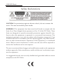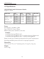
1
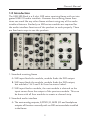
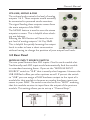
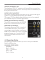
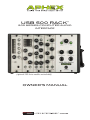
USB 500 RACK™
500 SERIES COMPUTER AUDIO
INTERFACE
(optional 500 Series modules not included)
OWNER’S MANUAL
USB 500 Rack
Safety Declarations
CAUTION: For protection against electric shock, do not remove the
cover. No user serviceable parts inside.
WARNING: This equipment has been tested and found to comply with the
limits for a Class A digital device pursuant to Part 15 of the FCC Rules. These
limits are designed to provide reasonable protection against harmful interference when the equipment is operated in a commercial environment. This
equipment generates, uses, and can radiate radio frequency energy and, if not
installed and used in accordance with the operating guide, may cause interference to radio communications. Operation of this equipment in a residential
area is likely to cause interference in which case the user will be required to
correct the interference at his own expense.
The user is cautioned that changes and modifications made to the equipment
without approval of the manufacturer could void the user’s authority to operate this equipment.
It is suggested that the user use only shielded and grounded cables to ensure
compliance with FCC Rules.
2
Owner’s Manual
Table of Contents
1.0 INTRODUCTION
5
2.0 FRONT PANEL
2.1 Four Slots
2.2 Power Button
2.3 Headphone Amps
2.4 Volume, Mono and Dim
6 6
6
6
7
3.0 REAR PANEL
3.1 Module Input Source Switch
3.2 USB Source Switch
3.3 Link Switch
3.4 Analog Outputs 1 & 2
3.5 S/PDIF I/O
3.6 Word Clock I/O
3.7 MIDI I/O
7 7 8
8 9 9 9
9
4.0 OPERATING MODES
4.1 Channel Strip Mode
4.2 XLR Line level Inputs
4.3 Hardware Inserts
9
9
10
11
5.0 INSTALLATION
5.1 System Requirements
5.2 Drivers and Firmware
5.3 Mac OS
5.4Windows
5.5 USB Connection
5.6 Audio Setup in Your DAW
5.7 Using USB 500 Rack with iPad
11 11 12
12
12
13
13
15
Copyright © 2013 by Aphex LLC. All rights reserved.
All Aphex LLC products are trademarks or registered trademarks of Aphex LLC.
Other brand and product names are trademarks or registered trademarks
of their respective holders.
3
USB 500 Rack
Table of Contents
(CONTINUED)
6.0 SPECIFICATIONS
16
7.0 WARRANTY & SERVICE
7.1 Limited Warranty
7.2 Service Information
17
17
18
4
Owner’s Manual
1.0 Introduction
The USB 500 Rack is a 4-slot, 500 series receiving frame with an integrated USB 2.0 audio interface. However the receiving frame functions can work like any other frame without using any of the audio
interface features. Similarly no 500 series modules are required for
the audio interface functions of the product to work properly. There
are four basic ways to use the product:
1. Standard receiving frame
A. XLR input feeds the module, module feeds the XLR output.
B. XLR input feeds the module, module feeds the XLR output,
but modules 1 & 2 and 3 & 4 can be stereo linked.
C. XLR input feeds a module, the next module is chained so the
input comes from the output of the previous module. This can
be done with all four modules to create a channel strip.
2. Standard audio interface
A. The main analog outputs, S/PDIF I/O, MIDI I/O and headphone
outputs all function normally with no 500 series modules installed
in the frame.
5
USB 500 Rack
B. The XLR inputs can be used as +4 line level inputs to the DAW
with no modules installed.
3. Recording the module outputs to the DAW
A. Use four microphone preamp modules to record four micro
phones to four individual tracks in the DAW.
B. Use one microphone preamp module and up to three process ing modules in “Chain mode” as a channel strip to record one
microphone to one track in the DAW.
4. Hardware inserts
A. Send four individual tracks or busses from the DAW to the
modules and return the processed signals back to the DAW
for mixing.
B. Send one individual track to be processed with a channel strip
of modules and return the processed signal back to the DAW
for mixing.
C. Send a stereo mix from the DAW through linked compressors
and EQs and return the processed stereo signal to a stereo aux
input in the DAW.
2.0 Front Panel
FOUR SLOTS
The unit features four slots for use with compatible 500 series
modules. Single and dual slot modules can be used. The rear panel
features an XLR input and output for each slot.
POWER BUTTON
When the power button is pushed on, the APHEX logo will light up
confirming that the unit is properly powered.
HEADPHONE AMPS
The USB 500 Rack includes two headphone outputs. Each output has
their own individual amplifier with volume control. Both headphone
amps receive one shared, assignable stereo signal from your DAW.
6
Owner’s Manual
VOLUME, MONO & DIM
The volume knob controls the level of analog
outputs 1 & 2. These outputs would normally
be connected to powered studio monitors.
The signal feeding these outputs comes from
the main outputs of the DAW.
The MONO button is used to sum the stereo
outputs to mono. This is helpful when checking mix balance.
Pressing the DIM button will lower the output level of analog outputs 1 & 2 by 20dB.
This is helpful for quickly lowering the output
levels in order to have a short conversation
without having to change the position of your output level knob.
3.0 Rear Panel
MODULE INPUT SOURCE SWITCH
The rear panel features four XLR inputs. One for each module slot.
Traditionally each XLR input would automatically feed the module
in a standard receiving frame. If you set the “MODULE INPUT
SOURCE” switch to “XLR” that is exactly what happens. However the
USB 500 Rack offers you other options as well. If you set the switch
to “USB” you can assign a DAW hardware output to the input of a
module for that module to become an analog hardware insert processor in your DAW. The switch can also be set to “MOD” meaning
that this module receives its input from the output of the previous
module. This setting allows you to set up a “Channel Strip.”
7
USB 500 Rack
USB SOURCE SWITCH
This switch determines what signal is sent to the USB stream to
appear as hardware inputs to your DAW. If the switch is set to
“MOD” then the output of that module becomes a hardware input
to your DAW. If the switch is set to “XLR,” the signal present at the
XLR input becomes the hardware input to your DAW. This second
mode can be useful when no modules are present or when you wish
to bypass a module, using the XLR inputs as line level inputs.
EXAMPLE:
A mic pre module is loaded in to slot 1. A microphone is plugged in
to the XLR input. What you want to record is the output of the mic
pre. In this case the switch should be set to “MOD.”
If you wanted to record the output of an external, rack mounted mic
pre, you would plug the output of the mic pre in to the XLR input of
the slot and set the switch to “XLR.” With the switch set to “XLR” the
input becomes a +4, line level input to the DAW.
NOTE: If there is an installed mic pre module, its phantom power
should be turned off prior to switching this to XLR.
LINK SWITCH
Some 500 series modules, like the Aphex COMP 500 compressor, have
stereo linking capabilities. The USB 500 Rack features a stereo LINK
switch for slots 1 & 2 and 3 & 4. Move these switches to the right to
engage the linking functions. Be sure to set these switches to the bypass
position, when NOT linking modules. Consult your module’s documentation for linking support.
8
Owner’s Manual
ANALOG OUTPUTS 1 & 2
These balanced TRS 1/4” outputs would normally be connected to a
pair of powered studio monitors. The output level is controlled by the
front panel volume knob.
S/PDIF INPUT & OUTPUT
The coaxial, 75-Ohm digital input allows you to record 24-bit digital
signals in to your DAW at sample rates up to 96kHz.
The coaxial, 75-Ohm digital output allows you to send an assigned
pair of DAW outputs to another digital device.
WORD CLOCK INPUT & OUTPUT
These BNC connectors allow the USB 500
Rack to be a word clock master or slave.
MIDI INPUT & OUTPUT
These jacks allow your DAW to send and
receive MIDI information. Uses include
connecting a control surface, send/receive
MIDI Clock or MIDI Time Code, send MIDI
program changes, etc. Consult the MIDI
section of your DAWs manual for more
information.
4.0 Operating Modes
The following examples will show you how to setup the USB 500
Rack for different uses.
CHANNEL STRIP MODE
EXAMPLE:
Slot 1 = Mic Pre
Slot 2 = Compressor
Slot 3 = EQ
Slot 4 = Exciter
9
USB 500 Rack
Slot 1 MODULE INPUT SOURCE set to “XLR.”
Slot 2 MODULE INPUT SOURCE set to “MOD 1.”
Slot 3 MODULE INPUT SOURCE set to “MOD 2.
Slot 4 MODULE INPUT SOURCE set to “MOD 3.”
This sends the microphone input to module 1. The mic pre output is
sent to the compressor; the compressed mic pre signal is sent to the
EQ. The compressed and EQ’d mic pre signal is sent to the Exciter.
The output of the Exciter can be sent to a single DAW track and the
XLR output of slot 4.
NOTE: Remember that the module output signals are ALWAYS
sent to their associated XLR outputs. Keeping with the signal flow
from this example, the output of the mic pre would be sent module
output 1, the compressed mic pre signal would be sent to module
output 2, the EQ’d and compressed mic pre signal would be sent to
module output 3 and the excited, EQ’d, compressed mic pre signal
would be sent to module output 4.
NOTE: Module one does NOT have a MOD selection as there is
no previous module to receive a signal from.
USING XLR LINE LEVEL, +4DBU INPUTS
Let’s say slots 2-4 have their MODULE INPUT SOURCE switch set
to “MOD.” This means the modules will derive their signal from the
output of the previous module. In this scenario the USB SOURCE
switch for slots 2 and 3 can be set to “XLR” allowing the XLR inputs
to be used as a +4 line level inputs to the DAW. A practical use of this
would be recording a vocal using all 4 modules chained as a channel
strip while using XLR inputs 2 and 3 with external preamps to simultaneously record an acoustic guitar, a bass and a harmony vocal.
Another way to look at this setup is as a module bypass. Setting the
“USB SOURCE” switch to XLR allows the signal connected to that
XLR to be sent directly to the DAW, bypassing the module.
10
Owner’s Manual
HARDWARE INSERTS
The USB 500 Rack can be used as an easy way to process DAW tracks
or busses with 500 series analog modules. Simply select the proper
hardware slot inputs and outputs on the track or buss insert within your DAW. Then set the MODULE INPUT SOURCE switches to
“USB” and the USB SOURCE switches to “MOD.” This will send the
signal from the DAW track or buss, convert it to analog, process the
signal, convert the signal back to digital and return the signal to the
DAW. All with one USB cable. Pretty cool!
NOTE: When using hardware inserts there are delay compensation
settings that must be made in your DAW. Consult the documentation for your DAW to learn how and where to make the proper
settings.
There are a few ways you can implement hardware inserts:
1. Send four individual tracks or busses from the DAW to individ ual modules and return the four processed signals back to the
DAW for mixing.
2. Send one individual track to be processed with a channel strip
of modules and return the processed signal back to the DAW
for mixing.
3. Send a stereo buss from the DAW through linked compressors
and EQs and return the signals to a new stereo aux input.
5.0 Installation
SYSTEM REQUIREMENTS
(please go to www.aphex.com for the latest information)
Apple Macintosh with Intel CPU and an available USB 2.0 port
OS: Mac OS X 10.5 – 10.8 and beyond.
Windows compatible computer with an available USB 2.0 port
OS: Windows XP SP3 (32-bit), Windows Vista SP2 (32-bit/64-bit),
Windows 7 SP1 (32-bit/64-bit).
11
USB 500 Rack
DRIVERS AND FIRMWARE
All drivers required by the USB 500 Rack are available for download from
the Aphex website. Be sure that you download and install the most up-todate drivers before you connect the USB 500 Rack to your computer.
If you don’t have Internet access, drivers are on the CD-ROM included in
the box.
MAC OS ONLY:
USB 500 Rack does not require special drivers on OSX. Just connect
USB 500 Rack to the Mac with a high quality USB cable and it will be
recognized automatically.
Your OS should automatically switch the computer’s default audio
outputs to be the USB port to which the USB 500 Rack is connected.
To verify this, go to System Preferences > Sound, and ensure that the
input and output are set to USB 500 Rack. For more detailed setup
options on a Mac, open Applications > Utilities > Audio MIDI Setup.
WINDOWS ONLY:
Before connecting USB 500 Rack to your computer, install the driver
from the included CD or from the driver installer you can download
from www.aphex.com. If Windows presents any dialogs during the
installation process, click OK, Accept or Allow. Connect USB 500 Rack
after the driver installation process has completed. Your OS should
automatically switch the computer’s default audio outputs to be
the USB port to which USB 500 Rack is connected. To verify this, go
to Start > Control Panel > Hardware and Sound > Sound > Manage
Audio Devices and ensure that “Default Playback” and “Recording”
are set to USB 500 Rack.
Some DAWs will not launch the USB 500 Rack control panel. Access it
from the Windows system tray in the lower right of your screen.
Except for Pro Tools, Aphex recommends setting the driver latency
(buffer size) in the Aphex driver control panel rather than in your
DAW. Pro Tools instructions are included on page 14.
12
Owner’s Manual
Additional Windows 7 notes:
The UI Theme must be sent to Windows Basic for best performance.
Right-click on the desktop and select “Personalize” to change this.
USB CONNECTION
The USB 500 Rack has a single USB 2.0 port on the rear panel. Once
the software installation is complete, simply connect the USB 500
Rack to your computer using the USB cable provided. Note that USB
500 Rack is a USB 2.0 device, and thus the USB connection requires
a USB 2.0 compatible port on your computer. It will not operate correctly with USB 1.0/1.1 ports. You MUST connect the USB 500 Rack
directly to your computer and NOT to a USB hub.
AUDIO SETUP IN YOUR DAW
After installing the drivers and connecting the hardware, you can start
using the USB 500 Rack with the DAW of your choice.
Once the USB 500 Rack is set as the preferred Audio Device in your
DAW, the following inputs will be available:
INPUTS
500 Rack Slot 1
500 Rack Slot 2
500 Rack Slot 3
500 Rack Slot 4
500 Rack S/PDIF 1
500 Rack S/PDIF 1
OUTPUTS
500 Rack Analog L
500 Rack Analog R
500 Rack Headphone L
500 Rack Headphone R
500 Rack Slot 1
500 Rack Slot 2
500 Rack Slot 3
500 Rack Slot 4
13
USB 500 Rack
S/PDIF 1
S/PDIF 2
NOTES to Pro Tools 9, 10 and 11 users:
When switching to the USB 500 Rack from another interface, you
must have that interface connected when launching Pro Tools for the
first time with the USB 500 Rack connected. Once Pro Tools has recognized it, the other interface may be left connected or disconnected.
Pro Tools will not launch properly if the interface it is expecting is not
connected.
Pro Tools 9 and 10 require the DAW to be exited and relaunched
when changing the hardware buffer size. Pro Tools 11 does not
unless Ignore Errors During Playback/Record is checked in the Playback Engine window.
Pro Tools will take control of the USB 500 Rack driver. Leave the
Lock Sample Rate checkbox in the driver control panel unchecked.
If you experience difficulty trying to set up your I/O with the USB 500
Rack, try this trick:
• Open Pro Tools.
• When the Pro Tools launch screen becomes visible, hold down
the “N”key on your keyboard. This allows you back door access
to the playback engine.
• Select the USB 500 Rack as your device and continue.
• Once Pro Tools finishes launching go to the Setup menu and
select I/O.
• Select the Input tab, delete all input paths and then select
New Path.
• Create 1 Mono Input and click Create. This path will be named
“Input.” You can double-click it and name it “USB 500 Rack.”
• Now click the box just right of “Mono,” under the ApMX icon.
An “M” will appear. Click OK.
• Now click the Output tab, delete all of the output paths and
select Default.
14
Owner’s Manual
• Open a new session and select “Stereo Mix” in the I/O Settings
drop down menu.
Once this is done the USB 500 Rack should work with your Pro Tools
system.
5.1 USING USB 500 RACK WITH IPAD
The Aphex USB 500 Rack has been tested and found to work with
iPad-2 and iPad-4 running iOS version 6.1.3 and using the Apple
Camera Connection kit and the Lightning to USB Camera Adapter.
USB 500 Rack was tested with the following apps:
• Apple GarageBand for iOS version 1.4 (180.6)
• WaveMachine Labs Inc. Auria version 1.091.
No other iPads, iOS versions or Apps were tested.
Please check www.aphex.com for up to date testing results with new
iPads, new versions of iOS and other apps.
NOTE: Apple does not officially endorse the use of the Camera
Connection kit and the Lightning to USB Camera Adapter for
anything other than camera connections. Further information
can be found at:
http://support.apple.com/kb/HT4106
15
USB 500 Rack
6.0 Specifications
USB 500 Rack Audio Performance Results
August 13, 2013
Audio Path
(un-wtd)
SNR
(A-wtd)
SNR
(@–1dBFS)
THD+N
Max Level
Module 1-4 ADC
112 dB
115 dB
0.001 %
26dBu
Module 1-4 DAC
107 dB
110 dB
0.002 %
26dBu
Main Out
107 dB
110 dB
0.002 %
26dBu
110 dB
< 0.015%
Headphone Out 107 dB
(75 ohm load)
22Vpp into 75ohm
Power:
90-240 VAC | 50/60Hz | 40W
Fuse: 250V/2A | 5mm x 20mm
880mA total power available to the slots
Examples:
4 modules drawing 220mA each
2 modules drawing 300mA each, 2 modules drawing 140mA each
2 modules drawing 400mA each, 1 module drawing 80mA
Please consult your module documentation for power requirements.
Exceeding available power will result in improper operation.
Dimensions:
10.5” W x 8.5” D x 5.5” H (26.6cm W x 21.5cm D x 14cm H)
Weight:
9 lbs. (4 kg)
16
Owner’s Manual
7.1 LIMITED WARRANTY
PERIOD
One year from date of original purchase.
SCOPE
All defects in materials and workmanship. The following are not covered:
• Voltage conversions.
• Units on which the serial number has been defaced, modified or
removed.
• Damage or deterioration resulting from: Installation and/or removal
of the unit; Accident, misuse, neglect, unauthorized product modifi cation; Failure to follow instructions in the Owner’s Manual, User Guide
or other official Aphex documentation.
• Repair or attempted repair by anyone not authorized by Aphex;
Shipping damage claims must be presented to the shipper.
WHO IS PROTECTED
This warranty will be enforceable by the original purchaser and by any
subsequent owner during the warranty period, so long as a copy of the
original Bill of Sale is submitted whenever warranty service is required.
WHAT APHEX WILL PAY FOR
All labor and material expenses for covered items. Aphex will pay all
return shipping charges if the repairs are covered by the warranty.
LIMITATION OF WARRANTY
No warranty is made, either expressed or implied, as to the merchantability
and fitness for any particular purpose. Any and all warranties are limited to
the duration of the warrant stated above.
EXCLUSION OF CERTAIN DAMAGES
Aphex liability for any defective unit is limited to the repair or replacement of
said unit, out our option, and shall not include damages of any kind, whether
incidental, consequential, or otherwise. Some states do not allow limitations
on how long an implied warranty lasts and/or do not allow the exclusion or
limitation of incidental or consequential damages, so the above limitations
and exclusions may not apply to you. This warranty gives you specific rights
which vary from state to state.
17
USB 500 Rack
7.2 SERVICE INFORMATION
If it becomes necessary to return this unit for repair, you must first contact
Aphex LLC for a Return Authorization (RMA number), which will need to
be included with your shipment for proper identification. If available, repack
this unit in its original carton and packing material. Otherwise, pack the
equipment in a strong carton containing at least 2 inches of padding on
all sides. Be sure the unit cannot shift around inside the carton. Include a
letter explaining the symptoms and/or defect(s). Be sure to reference the
RMA number in your letter and mark the RMA number on the outside of the
carton. If you believe the problem should be covered under the terms of the
warranty, you must also include proof of purchase. Insure your shipment and
send it to:
Aphex
3500 N. San Fernando Blvd.
Burbank, CA 91505 USA
18
Owner’s Manual
This page left intentionally blank (except for this note).
19
USB 500 RACK OWNER’S MANUAL
Copyright © 2013 by Aphex LLC. All rights reserved.
Aphex LLC, 3500 N. San Fernando Blvd., Burbank, CA 91505 USA
PH: (818) 767-2929 FAX: (818) 767-2641
www.aphex.com
Rev. A - 12/26/2013