1
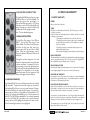
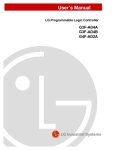
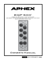
EQF 500
®
3 BAND EQ WITH HPF AND LPF
JENSEN TRANSFORMER BALANCED OUTPUT
500 SERIES MODULE
Owner’s Manual
SAFETY DECLARATIONS
CAUTION: For continued protection against risk of fire, replace
only with the same type and rating of fuse.
ATTENTION: pour une protection continue contre les risques
d’incendie, ne remplacer qu’avec la même valeur et même type de
fusible.
WARNING: Do not place objects containing liquid on this unit as
it is not designed to protect against spillage. Do not expose this
unit to dripping or splashing of liquids as the unit is not designed
to protect against these occurances.
SAFETY DECLARATIONS
This equipment has been tested and found to comply with the limits
for a Class B digital device, pursuant to part 15 of the FCC rules.
These limits are designed to provide reasonable protection against
harmful interference in a residential installation. This equipment
generates, uses and can radiate radio frequency energy and, if not
installed and used in accordance with the instructions, may cause
harmful interference to radio communications. However, there is
no guarantee that interference will not occur in a particular installation. If this equipment does cause harmful interference to radio
or television reception, which can be determined by turning the
equipment off and on, the user is encouraged to try to correct the
interference by one or more of the following measures.
WARNING: This unit must be connected to a mains socket outlet
with a protective earthing connection.
1. Reorient or relocate the receiving antenna.
WARNING: The EQF 500 has been tested and meets the FCC, CE
and European Union rules, regulations, and guidlines for use. Do
not attempt to modify or change the EQF 500, as this could void
the regulatory compliance, which would place you at risk of losing
your authority to operate the EQF 500.
3. Connect the equipment into an outlet on a circuit different from
that to which the receiver is connected.
2. Increase the separation between the equipment and receiver.
4. Consult the dealer or an experienced radio/TV technician for help.
WARNING: Do not place objects on top of this unit if they weigh
more than 10 pounds.
Page 2
Page 3
TABLE OF CONTENTS
1.0 INSTALLATION 1.0 INSTALLATION
2.0 INTRODUCTION
3.0 CONTROLS AND INDICATORS
3.1 High frequency controls 3.2 Midrange frequency controls 3.3 Low frequency controls 3.4 EQ and Filters On/Off buttons 3.5 Low and High Pass Filters 3.6 Shelving and peaking EQ 4.0 WARRANTY AND SERVICE
4.1 Limited Warranty 4.2 Service Information 5.0 SPECIFICATIONS
5
6
7
7
7
8
8
8
1. Turn off and unplug your 500 series rack frame. Inspect the
card slot you intend you use to make sure that it is clean and
free of any debris.
2. Before removing your EQF 500 from its box, discharge any
static electricity buildup you may have by touching your 500
series rack.
3. Pull your EQF 500 module out of its box and carefully slide
it into place in the designated opening. Sight down the back of
the module (use a flashlight if necessary) and ensure the card
edge connector is aligned to seat into the card slot of the frame.
9
10
4. Firmly and evenly push the EQF 500 module into place until
its is positively seated in the card slot.
11
5. Use the 2 thumb screws in the module to mount the EQF 500
front panel to the 500 series rack. These screws have a pretty
tight fit; please be careful not to cross thread.
6. Plug your 500 series rack back into the AC source and power
up your rack. Your EQF 500 will automatically power up with
your 500 series rack.
Page 4
Page 5
2.0 INTRODUCTION
The EQF 500 is a reissue that is our modern take on the classic
Aphex EQF-2 500 series equalizer. The original EQF-1 500 module
was designed in 1976 while the EQF-2 500 was an upgrade that
included shelving EQ for the high and low bands.
The newly designed EQF 500 module has an improved control
layout and modern components have been incorporated for lower
noise than the original. A Jensen JT11K8 nickel input Transformer
and Jensen JT-11DL nickel output transformer provide the cleanest
possible balanced input and output signal.
3.0 CONTROLS & INDICATORS
3.1 HIGH FREQUENCY CONTROLS
These controls let you optimize the high frequency band. The range is from 1kHz to 20kHz.
The selected frequency can be cut or boosted
by 12dB. Pressing the bell curve button
changes the high frequency EQ from a shelving EQ to a peaking EQ. The button will light
when it is in peaking mode. The bandwidth or
“Q” is preset to one octave at maximum boost.
3.2 MIDRANGE FREQUENCY CONTROLS
These controls lets you optimize the midrange
frequency band. The range is from 250Hz to
5kHz. The selected frequency can be cut or
boosted by 12dB. The bandwidth or “Q” is
preset to one octave at maximum boost.
3.3 LOW FREQUENCY CONTROLS
These controls lets you optimize the low
frequency band. The range is from 20Hz to
500Hz. The selected frequency can be cut
or boosted by 12dB. Pressing the bell curve
button changes the low frequency EQ from a
shelving EQ to a peaking EQ. The button will
light when it is in peaking mode. The bandwidth or “Q” is preset to one octave at maximum boost.
Page 6
Page 7
3.4 EQ & FILTERS ON/OFF BUTTONS
These lighted On/Off buttons allow you to turn
the EQ and filters on and off individually. The
buttons glow green when processing is on.
They are dark when processing is off. Turning
the button on and off offers a quick A/B comparison, allowing you to hear the affect the EQ
and filters have on the program content.
Note: These are hardwire bypasses.
3.5 LOW & HIGH PASS FILTERS
The High Pass Filter range is from 20Hz to
500Hz. The Low Pass Filter range is from
1kHz to 20kHz. The filters will cut all frequencies below the high pass filter and all frequencies above the low pass filter at 12dB/
octave. When set to their extremes, only the
frequencies between 500Hz and 1kHz are left
untouched.
Filtering the irrelevant frequencies of a track
allows the instrument stand out and provides
a cleaner overall mix. For example, the low frequency energy of an acoustic guitar track can
get in the way of the bass guitar and kick drum.
Filtering the low frequencies of the acoustic
guitar track makes the bass guitar and kick
drum sound tighter and more defined.
3.6 SHELVING & PEAKING EQ
High shelving EQ will boost or cut all frequencies above the selected
high frequency. Frequencies below that setting are untouched.
High peaking EQ will boost or cut only a small amount of frequencies above and below the selected high frequency. How many frequencies above and below is dependant on the bandwidth or “Q”
setting. The narrower the bandwidth, the less other frequencies are
affected. The EQF 500 has a bandwidth of one octave at maximum
cut or boost. Peaking EQ is used when only a specific frequency
needs to be boosted to highlight the character of a track or cut to
allow the remaining frequencies to be highlighted.
Page 8
4.0 SERVICE & WARRANTY
4.1 LIMITED WARRANTY
PERIOD
One year from date of purchase.
SCOPE
All defects in workmanship and materials. The following are not covered:
a. Voltage conversions.
b. Units on which the serial number has been defaced, modified, or removed
c. Damage or deterioration:
1. Resulting from installation and/or removal of the unit.
2. Resulting from accident, misuse, abuse, neglect, unauthorized product modification or failure to follow instructions contained in the User’s Manual.
3. Resulting from repair or attempted repair by anyone not authorized by Aphex Systems.
4. Occurring from shipping (claims must be presented to shipper).
WHO IS PROTECTED
This warranty will be enforceable by the original purchaser and by any subsequent
owner(s) during the warranty period, so long as a copy of the original Bill of
Sale is submitted whenever warranty service is required.
WHAT WE WILL PAY FOR
We will pay for all labor and material expenses for covered items. We will pay
return shipping charges if the repairs are covered by the warranty.
LIMITATION OF WARRANTY
No warranty is made, either expressed or implied, as to the merchantability
and fitness for any particular purpose. Any and all warranties are limited to
the duration of the warranty stated above.
EXCLUSION OF CERTAIN DAMAGES
Aphex Systems’ liability for any defective unit is limited to the repair or
replacement of said unit, at our option, and shall not include damages of
any other kind, whether incidental, consequential, or otherwise.
Some States do not allow limitations on how long an implied warranty lasts
and/or do not allow the exclusion or limitation of incidental or consequential
damages, so the above limitations and exclusions may not apply to you.
This warranty gives you specific legal rights, and you may also have other
rights which vary from State to State.
Page 9
4.2 SERVICE INFORMATION
If it becomes necessary to return this unit for repair, you must first contact
Aphex for a Return Authorization (RMA number), which will need to be
included with your shipment for proper identification. If available, repack
this unit in its original carton and packing material. Otherwise, pack the
equipment in a strong carton containing at least 2 inches of padding on
all sides. Be sure the unit cannot shift around inside the carton. Include a
letter explaining the symptoms and/or defect(s). Be sure to reference the
RMA number in your letter and mark the RMA number on the outside of
the carton. If you believe the problem should be covered under the terms of
the warranty, you must also include proof of purchase. Insure your shipment
and send it to:
APHEX
3500 N. San Fernando Blvd. Burbank, CA. 91505 USA
PH: 818.767.2929 FAX: 818.767.2641
5.0 SPECIFICATIONS
OPERATING LEVEL
+4dBu
Switch Setting:
INPUT
Type:
Impedance:
Unbalanced:
Nominal Level:
Maximum Level:
CMRR:
Transformerless, active balanced
40KΩ
20KΩ
+4dBu
+24dBu
>40dB
OUTPUT
Impedance:
Nominal Level
Maximum Level:
AUDIO
Frequency Response:
Dynamic Range:
THD:
IMD:
Page 10
110Ω
+4dBu
+24dBu Unloaded
+0.5dB 10Hz-38KHz
120dB
10Hz - 22kHz @ max output,
.0003%
10Hz - 22kHz 0 max output,
.0007%
CONNECTOR PINOUT
1
CHASSIS GROUND
2
OUTPUT + (+4 LEVEL)
3
(unused)
4
OUTPUT - (+4 LEVEL)
5
COMMON
6
(unused)
7
(unused)
8
INPUT- (+4 LEVEL)
9
(unused)
10
INPUT+ (+4 LEVEL)
11
(unused)
12
+16VDC
13
POWER SUPPLY COMMON
14
-16VDC
15
(unused)
This product is protected under one or more of the following Aphex patents.
5,450,034
6,266,423
3500 N San Fernando Blvd. Burbank, CA 91505 USA
PH: 818.767.2929 FAX: 818.767.2641
www.APHEX.com
Page 11