1
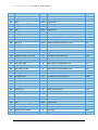
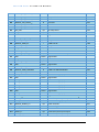
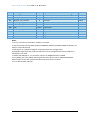
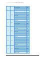
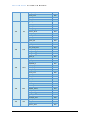
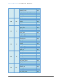
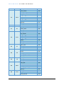
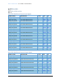
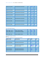
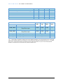
V A R - S O M - A M 4 3 S Y S T E M O N M O D U L E Interface Details Overview This chapter describes in detail the VAR-SOM-AM43 interfaces, referring to the default SoM pin names. However, many additional interfaces are available when different pin modes are selected by the user. PinMux Table 3.2 details the additional possible options for each pin on the VAR-SOM-AM43 connectors. The following list describes this chapter’s column header tables: Signal: VAR-SOM-AM43 original pin name Pin#: Pin Number on the SO-DIMM204 connector Type: Pin Type & Direction: I – In O – Out DS – Differential Signal A – Analog P – Power Pin Description: Short Pin functionality description Display Interfaces The general features of the DSS module include: • Display Controller - Display Modes • Programmable pixel memory formats (Palletized: 1, 2, 4, 8-bit per pixel; RGB 16, and 24-bit per pixel; and YUV 4:2:2) • Programmable display size (up to 2048 x 2048) • 256 x 24-bit entries palette in RGB • Programmable pixel rate (up to 80 MHz) - Display Support • Four types of displays are supported: Passive and Active colors, Passive and Active monochromes. • 4-/8-bit Monochrome Passive panel interface support (15 grayscale levels supported using dithering block) • RGB 8-bit Color Passive panel interface support (3,375 colors supported for color panel using dithering block). • RGB 12/16/18/24-bit Active panel interface support (replicated or dithered encoded pixel values). • Remote Frame Buffer (embedded in the LCD panel) support through the RFBI module • Partial refresh of the remote frame buffer through the RFBI module 51