1
Degree Project
Web services for a Software Development
Platform
Yue Wang
2010-08-17
Subject: Computer Science
Level: Master
Course code: 5DV00E
Abstract
Web service is a sophisticated SOA technology with a lot of infrastructure. In this
thesis we will get to understand the core aspects and advance futures of Web services
and get a solution based on Sauer-Danfoss’s requirements. The critical requirement
include to find appropriate Web services application server, to realize an automatic
update process and to get a general overview of Web services technology. The
challenges in this thesis is obviously in getting understand Web services architecture
and programming in unfamiliar language using chosen Web services framework.
Key Words: Web services, WSDL, UDDI, SOAP, Sauer-Danfoss, Axis2/C, PLUS+1.
i Acknowledgement
First and foremost, I would like to show my deepest gratitude to my presents, they are
always supporting me unconditionally. Also, I would like to thank my supervisor
Professor Welf Löwe for his enlightening instruction.
I shall extend my thanks to Fredrik Björn who comes from Sauer-Danfoss for his
excellent support. He took his time for my in one-on-one interviews and by Email
which provided necessary information and discussions to conduct this study. Without
his help I could not have completed my thesis.
Last but not least, I would like to thank teachers and friends from Linnaeus University.
I had a great time with them during my study in Sweden.
ii Content
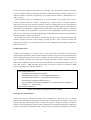
1. 2. 3. 4. Introduction...............................................................................................................................1 1.1 Context of Thesis ......................................................................................................1 1.2 Problem .....................................................................................................................1 1.3 Goals and Criteria .....................................................................................................2 1.4 Motivation.................................................................................................................2 1.5 Overview...................................................................................................................2 Web Services Technology Background.....................................................................................4 2.1 Introduction of Web Services ....................................................................................4 2.2 Transport and Massaging Service .............................................................................8 2.2.1 Transport ...........................................................................................................8 2.2.2 SOAP ................................................................................................................8 2.2.3 WS-Addressing ...............................................................................................10 2.3 Services Description................................................................................................12 2.3.1 WSDL .............................................................................................................12 2.3.2 WS-Policy .......................................................................................................14 2.4 Discovery and Binding Services .............................................................................15 2.4.1 UDDI...............................................................................................................15 2.5 Quality of Service ...................................................................................................18 2.5.1 WS-Security ....................................................................................................18 2.5.2 Reliable Messaging .........................................................................................23 2.5.3 Transactions ....................................................................................................24 2.5.4 File Transport Protocols (MOTM) ..................................................................28 2.5.5 Services Composition (BPEL Modeling Business Process)............................29 2.6 Apache Axis2/C Web Services Frameworks...........................................................31 2.7 Project Design Overview ........................................................................................32 2.7.1 Sauer-Danfoss PLUS+1 GUIDE Update Web Service ...................................32 Design Description..................................................................................................................36 3.1 Requirement Specification ......................................................................................36 3.1.1 System perspective..........................................................................................36 3.1.2 System Requirements......................................................................................37 3.1.3 Use-Case Specification ...................................................................................38 3.2 Architecture and Design..........................................................................................41 3.2.1 System Components........................................................................................41 3.2.2 System Interaction...........................................................................................43 3.2.3 Database Structure...........................................................................................45 3.3 Implementation .......................................................................................................46 3.3.1 Web Service System for Project......................................................................46 3.3.2 System Functions and Interaction Specification .............................................47 3.3.3 Database implementation ................................................................................53 User Manual............................................................................................................................57 4.1 Develop Environment .............................................................................................57 4.2 Apache Axis2/C ......................................................................................................57 iii 4.2.1 Environment Configuration.............................................................................57 4.2.2 Deploy Services ..............................................................................................58 4.3 MySQL Server for C ...............................................................................................59 4.4 IDE and Configuration............................................................................................59 5. Conclusion & Future Work .....................................................................................................61 5.1 Illustration of PLUS+1 Update System...................................................................61 5.2 Technical Conclusion ..............................................................................................65 5.3 Conclusion ..............................................................................................................66 5.4 Future Work.............................................................................................................66 References:......................................................................................................................................71 Appendix A: Using WSDL2C building Axis2/C Web Service .......................................................72 iv List of Figures
Figure 2. 1 Basic SOA Model ...........................................................................................................5 Figure 2. 2 Message-base Itegration .................................................................................................6 Figure 2. 3 Web Services Architecture..............................................................................................7 Figure 2. 4 SOAP Message Path .....................................................................................................10 Figure 2. 5 UDDI Data Model ........................................................................................................17 Figure 2. 6 Point-to-Point Security Model......................................................................................19 Figure 2. 7 End-to-End Scurity Model............................................................................................19 Figure 2. 8 WS-Security Model ......................................................................................................20 Figure 2. 9 Push Model of STS.......................................................................................................22 Figure 2. 10 Pull Model of STS ......................................................................................................22 Figure 2. 11 Reliable Messaging Model .........................................................................................24 Figure 2. 12 WS-Cordination Protocol Structure............................................................................26 Figure 2. 13 Atomic Transaction Model .........................................................................................28 Figure 2. 14 Business Transaction Model .......................................................................................28 Figure 2. 15 PULS+1 Update Architecture Overview ....................................................................33 Figure 2. 16 License Verification Part.............................................................................................34 Figure 2. 17 Update Process Part ....................................................................................................35
Figure3. 1 System Perspective ........................................................................................................36 Figure3. 2 Use-Case diagram of the system....................................................................................39 Figure3. 3 System Components ......................................................................................................42 Figure3. 4 Interaction of Plus Update Process ................................................................................44 Figure3. 5 Interaction of Plus File Transmit Process ......................................................................45 Figure3. 6 File Structure of the Web Service System .....................................................................47 Figure3. 7 Function Specification of Plus Update ..........................................................................48 Figure3. 8 Function Specification of Plus File Transmit ................................................................51 Figure 5. 1 Screen Shot of Client Side............................................................................................62 Figure 5. 2 SOAP Monitor of PLUS Update Procedure .................................................................70 Figure 5. 3 Server Side Fragment of PLUS Update Procedure.......................................................71 Figure 5. 4 Future Work Overview .................................................................................................75 Figure 5. 5 Future Work Transaction View .....................................................................................76 Figure 5. 6 Future Work Overview 2 ..............................................................................................76 Figure 5. 7 Future Work Overview 3 ..............................................................................................77 v List of Tables
Table 2. 1 SOAP Message XML Example ................................................................................9 Table 2. 2 WS-Addressing Endpoint reference Example........................................................11 Table 2. 3 SOAP Header XML Example ................................................................................12 Table 2. 4 WSDL Document Structure Example.....................................................................13 Table 2. 5 WS-Security XML Example ..................................................................................21 Table 2. 6 BPEL Structure Example........................................................................................30 Table 2. 7 BPEL Activities......................................................................................................30 Table 2. 8 Candidates Web Services Frameworks for C .........................................................31 Table 3. 1 System Requirements .............................................................................................37 Table 3. 2 Plus Upadate Use-case Specification .....................................................................40 Table 3. 3 Publish Service Use-case Specification..................................................................40 Table 3. 4 Plus File Trans Use-case Specification...................................................................41 Table 3. 5 User Service Use-case Specification ......................................................................41 Table 3. 6 Table uddi of Plus UDDI Database ........................................................................45 Table 3. 7 Table uddi_op of Plus UDDI database ...................................................................46 Table 3. 8 Table updatefiles of Plus Update database .............................................................46 Table 3. 9 Example content of uddi table................................................................................54 Table 3. 10 Example content of uddi_op table........................................................................54 Table 3. 11 Example content of updatefiles Table...................................................................55 Table 5. 1 SOAP Message of PLUS UDDI Requestor............................................................63 Table 5. 2 SOAP Message of PLUS UDDI Response.............................................................63 Table 5. 3 SOAP Message of PLUS Update Request .............................................................64 Table 5. 4 SOAP Message of PLUS Update Response ...........................................................64 vi Glossary
BPEL COM CORBA HTTP HTTPS J2EE MIME MTOM NASSL OASIS RM
SDL
SOA
SOAP STS
SMTP TCP
UDDI W3C WS
WSDL WSFL XOP
XML -
Business Process Execution Language
Component Object Model
Common Object Request Broker Architecture
HyperText Transport Protocol
Securer HyperText Transport Protocol
Java 2 Platform, Enterprise Edition
Multipurpose Internet Mail Extensions
Message Transmission Optimization Mechanism
Network Application Service Specification Language
Organization for the Advancement of Structured Information Standards
Reliable Messaging
Service Description Language
Service-Oriented Architectures
Simple Object Access Protocol
Security Token Service
Simple Mail Transfer Protocol
Transmission Control Protocol
Universal Description, Discovery, and Integration
World Wide Web Consortium
Web Services
Web Services Description Language
Web Service Flow language
XML-binary Optimized Packaging
Extensible Markup Language
vii 1. Introduction
Web services is a Service-Oriented Architecture technology - Through standardized Web protocol
it realized loosely coupled and standards-based aspect interoperability across platform. The core
composition technologies – XML, SOAP, WSDL and UDDI build the basic Web services
architecture and through further WS-* protocols enabling high quality performance software
services. Web services are changing the way people think about distributed system, in
business-level it provides reliable, flexible, extensible, loosely coupled and interoperable
middleware.
Sauer-Danfoss is a company which produces designs, manufactures, and markets engineered
hydraulic, electric and electronic systems and components. Their main software product is a
platform for development of embedded software called “PLUS+1 GUIDE”. It has 2 releases per
year and each release get 1 or 2 patches. At the moment all updates means manual work for their
users. They are looking for built-in auto-update functionality and they are interesting in Web
services technologies to solve this problem.
1.1 Context of Thesis
In this thesis we aim for implementing a software update solution by using Web services
technologies for Sauer-Danfoss software platform “PLUS+1 GUIDE”. The program should
automatically search for new patches and update software to release version. Our tasks include
finding the best way to implement automatic software updates and also to find the most
appropriate Web services framework for Sauer-Danfoss’s requirements.
Except the implementation of software update process, Sauer-Danfoss also want a general
introduce of Web services in this thesis. Through this thesis they want to get background
knowledge and an example solution about Web services and based on this information they could
use Web services technology in their future products.
1.2 Problem
Web service is a sophisticated SOA technology with a lot of infrastructure. In this thesis we will
get to understand the core aspects and advanced futures of Web services and get a solution based
on Sauer-Danfoss’s requirements. The critical requirement include to find a appropriate Web
services application server, to realize an automatic update process and get an general overview of
Web services technology. The challenges in this thesis are obviously to get understand Web
services architecture and programming in unfamiliar language using chosen Web services
framework.
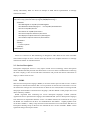
In generally, there are following problem in this thesis:
z Get to understand Web services architecture and aspects;
z How to introduce Web services to Sauer-Danfoss generally and comprehensively;
z Choose an appropriate Web services framework for Sauer-Danfoss requirements;
z How to build a suitable automatic software updates process;
z How to use Web services architecture to build server and client;
1 1.3 Goals and Criteria
The goals in this thesis are to implement a software automatic update process by using Web
services and give an introduction of Web services technology for Sauer-Danfoss. The criteria in
implementation are:
z Choose appropriate Web services framework and development kit in C language under
Microsoft Windows XP platform;
z Succeed to configure Web services server/client and compiler system;
z Write and deploy ‘Hello world’ Web service program by using multiple operations
server and client structure;
z The server could query patch information from database and send it back to client;
z Client side send current version information to server and get patch information
back.Based on the download address get patch files and repeated update to release
version;
z Complete reliability and extensibility of the services.
The thesis shall also give introduce of Web services technologies for Sauer-Danfoss. The
introduction should be general and comprehensive. The following aspects should be covered:
z Overview of Web services technology;
z The cores aspects of Web services: XML, SOAP, WSDL and UDDI;
z Advance protocol use in Web services: BPEL, WS-Security;
z The aspects enforce the quality of services: WS-ADDRESS, WS-Transaction, etc.
1.4 Motivation
In aiming to introduce Web services technologies to Sauer-Danfoss, we start from implementing a
software platform update process by using Web services to give them a brief illustration about the
advantage and usage of Web services. The process maybe too simple to shown the comprehensive
powerful ability of Web services but we also make a general introduction of Web services to
describe its most valuable perspectives for Sauer-Danfoss. From this thesis the final goal is to
recommend Web services technology to Sauer-Danfoss, so they could use Web services in their
future software products.
1.5 Overview
The structure of this thesis is:
Chapter 2: gives background acknowledges of Web services. First give an overview of Web
services technology and then introduce the detail aspects covering the basic and advanced level.
At last describe the software update process overview design in Web services architecture aspect.
Chapter 3: introduce the design and implementation of software platform update process. From
the functional structure and server/client architecture, it will introduce the system structure and
interactions between server and client.
Chapter 4: gives the user manual of the implementation. It describes the configuration of the
software platform process for Sauer-Danfoss. In this chapter will give introductions of how to
configure the Web services framework and the development kit and how to run the software
platform update program.
2 Chapter 5: make a conclusion of the thesis and gives the advice for Sauer-Danfoss. And we will
shows future work for this thesis.
3 2. Web Services Technology Background
In this chapter the goal is to introduce Web services - the most important technology used in this
thesis. It starts to give an overview introduction of Web services that gives the reader an
illustration of technology history, advantages and architecture. The following sections will
describe the selected Web services components and protocols for Sauer-Danfoss. After this chapter
the reader will have a general and clear image of Web services technology.
2.1 Introduction of Web Services
In mid to late 2000 Web Services technology was introduced with the first version XML
massaging – SOAP, WSDL 1.1, and a service register policy that was the initial version of UDDI.
Those standards build a wide accepted interoperability among software components. Companies
like IBM and Microsoft have been provided their Web services implementation products widely
used to solve business problems.
The World Wide Web Consortium (W3C) is running a Web Services Activity and its goals to
develop a set of technologies in order to lead Web Services to their full potential. The W3C
defines Web Services as follows:
“Web services provide a standard means of interoperating between different software
applications, running on a variety of platforms and/or frameworks. Web services are
characterized by their great interoperability and extensibility, as well as their
machine-processable descriptions thanks to the use of XML. They can be combined in a
loosely coupled way in order to achieve complex operations. Programs providing simple
services can interact with each other in order to deliver sophisticated added-value
services.” (W3C 2002)[1]
We could realize that the most valuable characteristics of Web services is using loosely coupled,
standards-based technologies, and those two aspects are also the key concepts of Service-Oriented
Architectures (SOA). The SOA is a methodology for achieving application interoperability and
reusability with the following features:
“
z A strong architectural focus, including governance, process, modeling, and tools.
z An ideal level of abstraction for aligning business needs and technical capabilities, and
creating reusable, coarse-grain business functionality.
z A deployment infrastructure on which new applications can quickly and easily be built.
z A reusable library of services for common business and IT functions.
” (Newcomer & Lomow 2005, p.3) [2]
The power and flexibility of SOAs can provide a services model that you can create new
services base on improve existing ones without leaving the services paradigm. It means that if
there is an organization gives its coarse-grained services and presents them in a clear functionality,
the consumers could dynamically discover and bind to the available services in a flexible way - to
build the application by composed services. The IT infrastructure behind those services can be
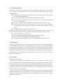
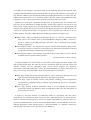
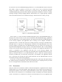
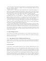
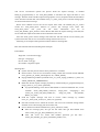
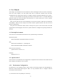
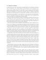
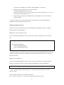
flexible and reusable. The basic foundation principle of SOA could be illustrated in Figure 2.1.
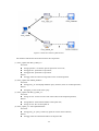
4 Figure 2. 1 Basic SOA Model
First, there need to be services which are presented with abstract definitions, including the detail
information that allows anybody who wants to use those services to and bind it. In the figure we
can see the ‘Requestor’ bind the specific ‘Services’ and acquire its functions. Second, the services
providers who want to let people find their services need to publish details of their service to a
facility. The details include precise description how people could obtain those services and
business information. Third, the published services need a discovery facility to let people find
those services. This illustration is the notion of a infrastructure that supports SOA, and the goal of
Web services technology is to address these questions.
“SOA represents an abstract architectural concept. It is an approach to build software
systems that is based on loosely coupled components (services) that have been described in
a uniform way and that can be discovered and composed. Web services represent one
important approach to realizing a SOA.” (Weerawarana et al. 2005, p.31) [3]
The different between Web services approach and traditional approaches first the loose coupling
aspect of the architecture. Traditional approaches build applications where the objects or
component are tightly related to each other by functionality requirement. But Web services do it in
more dynamic and adaptable way based on well known and understood services; second though
Web services themselves are developed in an open way, organizations such as W3C and the
Organization for the Advancement of Structured Information Standards (OASIS) provide Web
services in standards and technologies that are the foundation of the Internet.
The classic distributed system has a very important concept – components, the components
goals the reuse of tested partial solutions and easy system integration. This concept reduce the cost
for develop a new system, and that the new system has nice competition ability. But current
distributed system has issues: typically, current distributed system technology is based on object
systems. In that case, a service is similar to a method of a class implemented by an object. When
people want uses a single method of the service it needs to use the whole class. The requestor and
service are tightly coupled, when the service class hierarchy changes the requester must change
the application that uses that class. The interoperability is also a problem for current distributed
system. “Different distributed system technologies such as Common Object Request Broker
Architecture (CORBA), Java 2 Platform, Enterprise Edition (J2EE) and Component Object Model
(COM) are base on quite different and incompatible object models [Emm 2000].” (Weerawarana
5 et al. 2005, p.10) [3] The interoperability between those platforms is difficult.
Web services provide a solution about object system and interoperability issue of classic
distributed system. We could see Web services more like an adopter, now when Web services have
moved towards an XML based Message-Oriented middleware. Web services adapters wrap
existing applications which need be integrated. XML transforming the message into a format that
both sender and receiver could understand. Finally we could integration any application services
with others even in different system platform or programming language, and people could modify
and develop new application base on their requirements. XML standard based message-base
architecture makes Web service different from classic distributed system, “it allows the separation
of grammatical structure (syntax) and the grammatical meaning (semantics), and how that is
processed and understood by each service and the environment it exists in.” (IBM Developer
Works) [4]
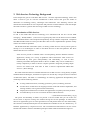
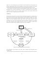
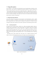
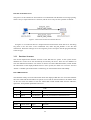
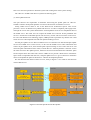
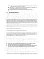
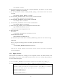
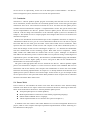
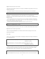
Web services provide interoperability between multiple languages and system platforms, but
you need build the services first. Figure 2.2 shows a Web services adapter A that warps a
application A. Adapter A format message M to standards XML form sent to the channel, which
transforms the message into format M’ and delivers it reliably to target adapter B. Adapter B parse
the message and understand how to pass the data to application B.
Figure 2. 2 Message‐base Itegration
Based on this Web services architecture, the application A and B are loose coupled, to further
view Web services could unite any kind of application with another if they are designed to the
appropriate interface. With above concept in mind, Web services allow you to:
“
z Interact between services on any platform, written in any language.
z Conceptualize application functions into task, leading to task-oriented development and
workflows. This allows a higher abstraction of software that can be employed by less
software-technical users that work on business level analytics.
z Allow for loose-coupling, which means that interactions between service applications
may not break each time there is a change in how one or more services are designed or
implemented.
z Adapt existing applications to changing business conditions and customer needs.
z Provide existing or legacy software applications with service interface without changing
original applications, allowing them to fully operate in the service environment.
z Introduce other administrative or operations management functions such as reliability,
accountability, security, etc., independent of the original function, thus increasing its
versatility and usefulness in the business computing environment.
6 ” (IBM Developer Works) [4]
Web Services is primarily an integration technology, but it is an independent form in itself. The
most composition technologies of Web services use XML based defined and communication. Thus
XML is a kind of independent language, so are Web services. So the Web services could be
developed by many programming language such as Java, Python, Perl, C#, Basic and etc. The
standards relevant for Web services such as XML, XML Schema, SOAP, WSDL, UDDI and more,
are manage by W3C and OASIS. Although those standards have been used to demonstrate Web
service in practice, there is a desire to use the approach to address more complex and difficult
problem. Developers are looking for an enhancements solution to raise the level of Web services
performance achieving commercial needs. More and more new Web services policy and
middleware are providing infrastructure services in support for transactions, security, or reliable
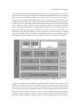
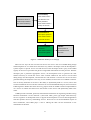
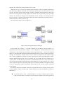
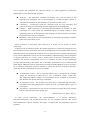
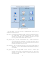
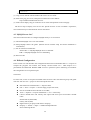
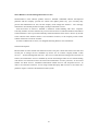
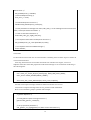
exchange of messages. Figure 2.3 shows the illustration of Web services architecture with the
standard specifications that IBM, Microsoft, and other significant IT companies have developed.
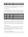
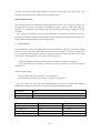
Figure 2. 3 Web Services Architecture (Weerawarana et al. 2005, p.34) [3]
Figure 2.3 describes a very high-level introduction to these Web services specifications. The
bottom layer ‘Transport’ presents its communication between a requester and a servicer to cope
with various transport protocols. One layer up, the massaging layer shows the massaging protocols
used to communicate between applications, which are based in XML technology. The description
layer shows the description of services in terms of function support and supported binding
mechanisms. Layer of ‘Quality of Service’ shows the features that provide future Web services
performance based on appropriate parameterization via polices resided in the layers that follows,
7 including the reliable massaging transmit with various kinds of transactions and security aspects,
such as message integrity, confidentiality. The top layer represents the various kinds of virtual
components that Web services represent. Composed services that the service bus inherently
supports are choreographies and societies of services that cooperate with BPEL, WS-C etc. The
UDDI layer provides the features for services description and discovery model between requesters
and services provider which are agreed by the OASIS and W3C.
This section represented the scope of the Web services architecture with a high-level overview
and aim to let people understanding of the structure and composition of Web services technology.
In the following section we will introduce the specific protocol and policy used in Web services,
and show how foundation Web services architecture work and how to build additional higher-level,
value-added infrastructure and business services by using enterprise Web services components.
Also we will analyze the project requirement from Sauer-Danfoss, and give a brief system
architecture overview.
2.2 Transport and Massaging Service
This section will introduce the most fundamental technologies of Web services. Its covers the
basic two layers ‘Transport’ and ‘Massaging’ in the Web services architecture framework. They
are underpinning how Web services applications communicate with each others and exchange
massaging.
2.2.1
Transport
Web services are built up like an interoperable messaging architecture, and the transport
technology are the foundation of this architecture. Web services is inherently transport neutral, so
you could transport Web services messages though the ubiquitous Web protocols such as
HyperText Transport Protocol (HTTP), Simple Mail Transfer Protocol (SMTP), Transmission
Control Protocol (TCP) or Securer HTTP (HTTPS), also you could transport them over any
communication protocol using proprietary ones such as MIME and IBM WebsphereMQ. The
transport protocols are fundamental to Web services because it is a defining factor in the scope of
interoperability, but most time during design Web services application development the transport
protocols details was hidden because consideration of the flexibility and platform interoperability.
2.2.2
SOAP
SOAP (Simple Object Access Protocol), one of the significant underpinnings of Web services,
provides a simple and relatively lightweight mechanism for exchanging structured and typed
information between services. “SOAP is designed to reduce the cost and complexity of integrating
applications that are built on different platforms. SOAP has undergone revisions since it
introduction, and the W3C has standardized the most recent version, SOAP 1.2.” (Weerawarana et
al. 2005, p.37) [3]
SOAP was born as the Simple Object Access Protocol, which developed by Microsoft
Developmentor, and Userland. At the beginning SOAP was not in a good situation and not many
people use it. During the evolution, IBM and Lotus contributed to a revised specification that
resulted in SOAP version 1.1 [SOAP 1.1] publish in April 2000. This specification was widely
8 accepted by the people and this version influence several open source interoperable
implementations. WS-I.org adopted it as part of its basic profile. In May 2000 the W3C took the
SOAP 1.1 and it in charge to preserve standardized new generation.
As we know SOAP is the fundamental messaging framework for Web services. With SOAP the
services could be provided by a loosely coupled infrastructure, and users could flexibly use
different implementation technologies and network transport protocols. SOAP provides the
following four main capabilities:
“
A standardized message structure based on the XML Infoset.
A processing model that describes how a service should process the message.
A mechanism to bind SOAP message to different network transport protocols.
A way to attach non-XML encoded information to SOAP message.
” (Weerawarana et al. 2005, p.63) [3]
SOAP defines an extensible message handle mechanism that scopes and structures the message
enveloping model and the message exchange between Web services. A common SOAP was
documented in XML form with three key parts: an envelope, a header, and a body. Usually, the
envelope is the root element of the SOAP massage; it contains zero or more headers and at least
one body. The header in an optional part of SOAP massage and it is a generic mechanism for
adding extensible features to SOAP. The child element of the header are called head block. SOAP
defines several well-known attributes that you can use to indicate who should deal with a header
block and whether processing of it is optional or mandatory. The mandatory body element always
is the last child element of the envelope, it include the actual payload message content. SOAP
defines when a message does not have any built-in header blocks and only one payload, which is
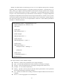
the Fault element used for reporting errors. Table 2.1 is an SOAP message example:
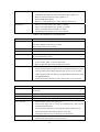
<?xml version=’1.0’ encoding=’UTF‐8’ ?> <soapenv:Envelope xmlns:soapenv=http://www.w3.org/2003/05/soap‐envelope> <soapenv:Header> … (Header Blocks) </soapenv:Header> <soapenv:Body> … (Body sub‐elements) </soapenv:Body> </soapenv:Envelope> Table 2. 1 SOAP Message XML Example
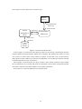
SOAP is designed to provide an independent, abstract communication protocol capable of
bridging, or connecting, two or more businesses or two or more remote business sites. “A SOAP
message is the basic unit of communication between SOAP nodes. A SOAP node is an
implementation of the processing rules described within the SOAP specification that can transmit,
receive, process, or relay a SOAP message.” (Weerawarana et al. 2005, p.65) [3] SOAP nodes
could send and receive SOAP messages. When a SOAP node transmit massage, it is called a
SOAP sender if it receives a message, it is called s SOAP receiver; some of SOAP node could
9 both send and receive message, we call them SOAP intermediaries. The first SOAP node that
builds and sends SOAP message is called the initial SOAP sender. The destination of SOAP
message is called the ultimate SOAP receiver. The ultimate SOAP receiver is responsible for
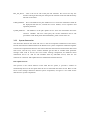
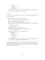
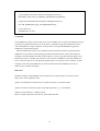
processing the message payload which is contained in the SOAP body. Figure 2.4 shows the
SOAP message path from initial SOAP sender to the ultimate SOAP receiver.
Figure 2. 4 SOAP Message Path
However SOAP messages are transmit one way from initial sender to ultimate receiver, but
multiple one-way messages can be combined into more sophisticated message patterns. There is a
simple solution for this problem, it is called message exchange patterns (MEP), and both
synchronous and asynchronous message request/response patterns are used in SOAP message
exchange.
In practice some applications need to send large amounts of binary data in a SOAP message.
Normally the binary data is nontextual information such as video/audio, images, or executable
files. In the standardized serializations for SOAP, XML allows only characters messages are
permitted. “There are two solution of this problem: the SOAP Message Transmission Optimization
Mechanism (MTOM) and the XML-binary Optimized Packaging (XOP).” (Weerawarana et al.
2005, p.81) [3] MTOM provides a way to identify any element information item in the SOAP
message Infoset as a candidate for optimization. XOP specifies a way to serialize the various
optimized elements and package them in the message to be transmitted.
This section described SOAP, which is the foundation messaging framework for Web services.
It covers the simple SOAP structure and transmit model. Also how to deal with SOAP massages
and transmit large binary files through SOAP. This extension mechanism enhanced Web services
architecture to compose and process complex messages.
2.2.3
WS-Addressing
In enterprising Web services implementation, the message senders and receivers need be
indentified in some scenario. SOAP only provides a basic message communication pattern may
not satisfied in advanced usage, but in Web services technology we have WS-Addressing protocol
to handle this situation.
“WS-Addressing provides an interoperable, transport-independent way of indentifying message
senders and receivers that are associated with message exchange. Web-Addressing decouples
address information from the specific transport method used by providing a mechanism to place
the target, source, and other important address information directly within the Web service
message. This specification defines XML elements to indentify Web services endpoints and to
10 secure end-to-end endpoint identification in messages. This specification enables messaging
systems to support message transmission through networks that include processing nodes such as
endpoint managers, firewalls, and gateways in a transport neutral manner.” (Weerawarana et al.
2005, p.39) [3]
Most important usage of WS-Addressing is used to identify and exchange Web services
between multiple end points. “With a standard way to express where a message should be
delivered in a Web services network, developers are able to simplify Web services communication
and development and avoid the need to develop costly, and hoc solutions that are often difficult to
interoperate across platforms.” (IBM Developer Works 2007) [11] Also WS-Address is a key part
of the core Web services architecture, it provide a protocol independent, common way to locate
Web services. Particularly in WS-ReliableMessaging, WS-Federation and WS-AtomicTransaction
it is the foundation of those specifications.
WS-Addressing provides two kinds of interoperable constructs that carriage information that
normally transports protocols and messaging systems provides. These constructs transfer this
underlying information into a uniform format that can be independently processed by application.
These constructs are:
Endpoint References
A Web services endpoint is a resource, and it can be referenced in that Web services messages
could target the destination. When used the endpoint reference conveys the message information it
needs to identify/reference a Web services endpoint. So you could use them in several different
ways. “Endpoint references are suitable for conveying information which is needed to access a
Web services endpoint, but are also used to provide addresses for individual messages sent to and
from Web services.” (IBM Developer Works 2007) [11] Table 2.2 shows an example of XML
Infoset representation of endpoint references:
<wsa:EndpointReference> <wsa:Address>xs:anyURI</wsa:Address> <wsa:ReferenceProperties>... </wsa:ReferenceProperties> ? <wsa:ReferenceParameters>... </wsa:ReferenceParameters> ? <wsa:PortType>xs:QName</wsa:PortType> ? <wsa:ServiceName PortName="xs:NCName"?>xs:QName</wsa:ServiceName> ? <wsp:Policy> ... </wsp:Policy>* </wsa:EndpointReference> Table 2. 2 WS‐Addressing Endpoint reference Example
Message Information Headers
Except conveying the information by Web services endpoint, in some cases a way to provide
addresses for individual messages that are sent to and from Web services is needed. To solve this
problem, the WS-Addressing provides a solution by define a family of message information
headers. In this specification it allows uniform addressing of messages independent of underlying
transport. The message information header contains source and destination endpoints and message
11 identity individually. Table 2.3 shows an example of XML Infoset representation of message
information header:
<S:Enveloper xmlns:S=http://www.w3.org/2003/05/soap‐envelope xmlns:wsa=”http://schemas.xmlsoap.org/ws/2004/08/addressing”> <S:Header> <wsa:MessageID> xs:anyURI </wsa:MessageID> <wsa:RelatesTo RelationshipType="..."?>xs:anyURI</wsa:RelatesTo> <wsa:To>xs:anyURI</wsa:To> <wsa:Action>xs:anyURI</wsa:Action> <wsa:From>endpoint‐reference</wsa:From> <wsa:ReplyTo>endpoint‐reference</wsa:ReplyTo> <wsa:FaultTo>endpoint‐reference</wsa:FaultTo> </S:Header> <S:Body> … <!‐ ticker symbol> </S:Body> </S:Enveloper> Table 2. 3 SOAP Header XML Example
Above two constructs of WS-Addressing are designed to make Web services more extensible
and reusable. People can have a choice when they decide to use endpoint references or message
information headers for suitable situation.
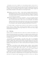
2.3 Services Description
Description of deployed services is a key aspect of Web services technology. Those descriptions
define metadata that fully describe the characteristic of services which is fundamental to achieving
the loose coupling. It also accord with SOA architecture and provide the abstract information to
deploy or interact with services.
2.3.1
WSDL
Web Services Description Language (WSDL) is the most mature aspect in Web services. It allows
developers to describe the functions that a service performs. It tells the user what actions a service
do and how the messages are received and sent. In Web services world, SOAP is a message format
that people understand the communication ‘language’, and then WSDL is what people uses to tell
others what they could do.
WSDL originated from combining two service description languages: NASSL (Network
Application Service Specification Language) from IBM and SDL (Service Description Language)
from Microsoft. In September 2000 the version 1.0 WSDL released, but continued in next years
the WSDL was submitted to the W3C for standardization and WSDL 1.1 slightly updated come
out in 2001. WSDL 1.1 widely accept and used in describe Web services. Recent the Web Services
Description Working Group of the W3C has released the new version of WSDL. WSDL 2.0 has
significant changes and improvements.
12 “WSDL is an XML format for describing services as a set of endpoints that operate on message
containing either document-oriented or procedure-oriented information.” (Weerawarana et al.
2005, p.40) [3] It supports describing endpoint and transport messages separate from message
formats or network protocols that are used to communicate. A typical WSDL document contains
two parts: first, abstract definition part which defines SOAP messages in a language-independent
and platform-independent manner that describes the operational behavior of Web services; second,
concrete descriptions part that defines site-specific matters such as serialization, and likes describe
how and where people to access a service implementation. Table 2.4 is a brief XML representation
of WSDL 1.1 document structure:
<wsdl:definitions name=”..” targetNamespace=”uri”> <import namespace=”uri” location=”uri”/> <wsdl:types> … </wsdl:types> <wsdl message name=”..”> … </wsdl:message> <wsdl:portType name=”..”> … </wsdl:portType> <wsdl:binding name=”..” type=”..”> … </wsdl:binding> <wsdl:service name=”..”> <wsdl:port name=”..” binding=”..”> … </wsdl:port> … </wsdl:service> <‐‐ extensibility element ‐‐> </wsdl:definitions> Table 2. 4 WSDL Document Structure Example
The major elements in above WSDL example:
z definitions – defines a bag of definitions for a single namespace;
z types – provides data type definitions used to describe the message exchanged;
z message – represents the description of messages exchanged in the Web service;
z portType – is a set of abstract operations;
z binding – specifies concrete protocol and data format specifications for the operations
and messages defined by a particular portType;
z port – specifies an address for a binding, contains the endpoint address itself and refer to
a binding;
z Service – is used to aggregate a set of related ports.
13 Descriptions of the services in WSDL try to avoid describing semantics of Web services. A
WSDL document only tells people the services syntax and structure and what messages go in and
come out. It does not provide any information about the semantics. So WSDL plays a critical role
in enabling many of the advantages of Web services technology such as loosely coupling and
future proofing. And WSDL is used in Web services in two major scenarios:
Describing a service for its clients – In this scenario, the WSDL document describes a
published Web service for its clients. It tells clients where and how to access this service;
the exchange message declarations; service function operations; in addition to mechanisms
for interacting with the service. The main purpose of this scenario is enables a client of that
service to use that service effective.
Describing a standard service for service implementers – In this case, the WSDL document
more like standard service. For example, there is a service WSDL document description,
and a services provider wants to create a service for this description. The document
standards message formats and the interactions involved in this service, and the provider
has to agree with it. The services provider starts with that WSDL document and offers the
service, after that its client could follow the WSDL document and access to this service.
In conclusion, WSDL is a significant aspect in Web services and it describes services within a
few key aspects: the message formats, the message interaction patterns, the way the message
should be represented, and where those messages should be sent. It achieves the loosely coupling
and extensibility of a SOA scenario.
2.3.2
WS-Policy
WS-Policy defines an extensible framework for Web services constraints and conditions on an
interaction between multiple Web service endpoints. It is intended to provide a definition for the
services to annotate their interface definitions, to describe the policy, ensure their service qualities,
and specific policy requirement by a machine-readable expression form containing combinations
of individual assertions.
The motivation of creating WS-Policy is the Web services need for an interoperable,
standardized representation of nonfunctional capabilities and requirement of a services endpoint.
Compare to WSDL which already provides the basic functional description but only for the
service endpoint, the WS-Policy is an extension to achieve high-level usage such as transmission
reliablility, message security and so on. There are three major reasons to explain why we need
WS-Policy:
“First, there is the benefit of clearly separating concerns, avoiding a single monolithic
specification to deal with all the diversity of service description information.” (Weerawarana et al.
2005, p.129) [3] Although WSDL already represent a clear functional description, the
nonfunctional description and quality of service aspect need to be specific in high-level business
use, such as semantics, reusable specification, compose specification and so on.
“Second, the use of polices in not limited to service endpoints, but encompasses a variety of
possible subjects, even when considering the service-oriented environment.” (Weerawarana et al.
2005, p.129) [3] WS-Policy use XML documents state out legitimate subjects on which polices
will need to be asserted to ensure interoperability for services. In this case, we could say
14 WS-policy provide a flexible, extensible policy attachment mechanism for the association between
policy with subjects.
Third reason is because WSDL is not designed to support higher usage likes associate with
attachment mechanism, there is the need for incremental addition of capabilities to an existing
service. In a view with development and systems management perspective, it requires the common
standards to renovate the services offering with additional capability which is available within a
deployment environment. For example, add confidentiality, authentication, and supports for
reliable messaging protocols and so on to a service it needs WS-Policy to make a clear
description.
The WS-Policy framework is composed by WS-Policy and WS-PolicyAttachment.
“The WS-Policy specification describes the grammar for expressing policy alternatives
and composing them as combinations of domain assertions. And the
WS-PolicyAttachment specification describes how policies associate with a particular
subject. For this architecture, WS-Policy is intrinsically extensible, relying on
discipline-specific assertion to represent discipline-specific properties, such as security
policies, transaction polices, and business-specific policies.” (Weerawarana et al. 2005,
p.130-131) [3]
From above paragraph, we could know WS-Policy focuses on expressing two types of metadata:
capabilities which mean what a service can do and constraints that mean what things a service
require. And WS-Policy concern lot of specific Web service policies such as WS-Security,
WS-Reliable messaging and WS-Transaction and so on, which is the future use of WS-Policy in
higher level usage. WS-Policy defines a general-purpose framework for represent and combine
those Web service quality aspects properties.
2.4 Discovery and Binding Services
The transport, description, and message layer are the fundamental of Web services, its means with
those three layers people could build the minimal Web services platform to communicate in an
interoperable way using messages. But in SOA architecture, discovery services and negotiation are
very important aspects, it need a way to provide the features for discovery of services and the
descriptions about the agreement between a requester and a service. In this section, we will
introduce the most used Web services technologies to solve this problem.
2.4.1
UDDI
The Universal Description, Discovery, and Integration (UDDI) is an important Web services
aspect which is widely accepted and used. It provides a solution for users to find required services
from a well-known facility or registry their own services. In this scenario, the services metadata
could publish in a form that is discoverable and searchable by users who are looking for
appropriate services they require to solve their particular problem. Also, the organizations might
be able to publish their services by register the metadata describing the interfaces to their services,
and enable domain-specific taxonomies of services.
“UDDI began as collaboration among Microsoft, IBM, and Ariba to promote the adoption and
15 use of Web services standards.” (Newcomer 2002, p.153) [5] Though the rapid development, those
companies founded UDDI.org and invited more and more groups and companies to participate. In
July 2002 the UDDI.org was absorbed by OASIS and SAP replaced Ariba as a registry host site.
UDDI evolution goes from v1 to v3. Currently UDDI v3 has been widely acknowledged and used.
Compared to v2 it is a pretty improvement and with specifically improved security.
UDDI has two main parts: registration and discovery. In registration part, the businesses can
post their services information to UDDI repository so that other businesses can search for and
discover them, which is the discovery part. The businesses and individual users could interact with
UDDI by using SOAP APIs or the user interfaces provided by the operator or other Web services
vendors, for example the developers can find service from companies own web site or its own
UDDI repository. Normally, UDDI repositories could be provided in one of three ways:
“
Public UDDI – These are UDDI repositories that can serve as a resource for Internet-based
Web services. An example of this is the UDDI Business Registry [UBR] – hosted by a
group of vendors led by IBM, Microsoft, and SAP – that is replicated across multiple
hosting organizations.
Intra Enterprise UDDI – An enterprise has a private internal UDDI repository that provides
much more control over which service descriptions are allowed to be placed there and used
by application developers within that specific enterprise.
Inter Enterprise UDDI – This basically scopes the content of the UDDI to services that are
shareable between specific business partners.
” (Weerawarana et al. 2005, p.43) [3]
Comparing UDDI in real world model, it is more like a yellow page phone book. People could
find the information about who offer the services; information about the particular family and
technical offering; and the information about services access endpoint and integration
specification. The UDDI information is often described individually so people could search and
query in a nice way. Normally UDDI contains three main categories of business:
White Page: include the business name and address, contact information, Web site name, and
Data Universal Numbering System (DUNS) or other identifying number.
Yellow Page: “Type of business, location, and products, including various categorization
taxonomies for geographical location, industry type, business ID, and so on.” (Newcomer
2002, p.157)[5]
Green Page: Include technical information about a service endpoint and integration
specification. Future use tModel (a kind of UDDI data model) form the descriptions of
specification for services.
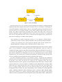
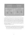
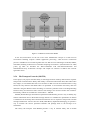
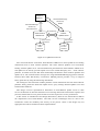
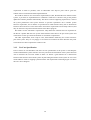
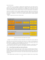
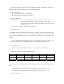
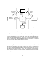
In Figure 2.5 the main elements of UDDI data model are represented. The color shows
categorization we mentioned at above. The arrow from <publishAssertion> to <businessEntity>
shows an association between them, its means two related <businessEntity> must have their own
separated <publishAssertion> to shows the relevant between them. And the <tModel> seem as the
technical information model which include by <businessTemplate>. In <tModel> contains the
information that describe services specification, likes WSDL etc.
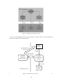
16 publisherAssertion: Information about a relationship between two <businessEntity> businessEntity: Information about the business unit who publishes information about a family of services businessService: Descriptive opration information about a particular service businessTemplate: Technical information about a service entry point tModel: Descriptions of specifications for services Figure 2. 5 UDDI Data Model (Löwe 2008)[6]
There are two ways the user can discover the services: first is the use of UDDI during design
and development or we could call it static discovery. When a developer starts the development a
system requires a specific service. To find the service the developer sends a query to the UDDI
registry for all service providers and gets the categorized information from the provider. Then the
developer pick a particular appropriate service, use development tools to generate the code
artifacts necessary to invoke the service. This scenario suitable for the services can be found
during design and development, and because the code artifacts of invoke the service has been
generated during development so this way is less reusable; Second is the use of UDDI at runtime.
One of the key attributes of an SOA is the ability to dynamically bind to a service, and in this
scenario suitable for the services like a business service needs find/bind best price, best terms from
UDDI registries. Rather than static discovery, people could use UDDI to find an implementation
of a service at runtime and then access the location of the service and dynamically bind to the
client.
“UDDI provides a flexible, powerful, and extensible mechanism for registering and discovering
business information over the Internet.” (Newcomer 2002, p.186) [5] People could discovery
services registries at development time to support the development of service-based application
and also dynamic discovery and binding services. These are two of the fundamental aspects of
SOA architecture, and UDDI plays a role to making the Web services framework a true
instantiation of the SOA.
17 2.5 Quality of Service
In above sections, we already introduced most fundamental technologies of Web services. Those
technologies constructed the basic infrastructure of message interaction between a services
requestor and provider. When people pursuit the higher and more reliable system such as security
message transaction, reliability of message delivery and support for transactions. In this scenario,
we need specify Web services in a quality aspect, so this section we will introduce some Web
services specifications and technologies aimed at experienced and quality usage. They are
including: security, reliable messaging, supporting of transactions and a specification technology
transport binary message which will be used in the thesis project.
Furthermore we will introduce WS-BPEL, which provide a definition of the business semantics
of Web services.
2.5.1
WS-Security
Security is one of the fundamental factors in enterprise software application. The important Web
services messages between service requestor and provider need be conveyed in secured
environment. WS-Security is the basic building block for secure Web services. WS-security uses
existing security models such as Kerberos and X509 building fundamental security and the
WS-Security family specifications concretely define the interoperable way to use the existing
models. Although Web services could use transport-level security functions (such as HTTPS and
BASIC-Auth authentication) provide a basic minimum for secure communication, but it is
insufficient for multiparty Web service computations.
Web Services Security (WS-Security) is a family of specifications provides comprehensive
secure communication. The family has many specifications associate with different requires and
models, such as:
WS-Security – SOAP Message Security 1.0 provides the foundation for security, support
with indentify the origin authentication message, detecting the integrity of message and
ensuring the confidential recipient access the message.
WS-Trust – use Security Token Service (STS) to verifying trust relationships. Public key
security works only if the certificate authorities are trusted by sender and receiver.
WS-SecureConversation – it provide similar support for WS-Security. “Participants
often use WS-Security with public keys to start a conversation or session, and they use
WS-SecureConversation to agree on session specific keys for signing and encrypting
information.” (Weerawarana et al. 2005, p.45) [3]
WS-Federation – use WS-Trust and WS-SecureConversation to make a federated
security though multiparty Web services domains.
Advanced security specifications: WS-Privacy and WS-Authorization.
Although WS-Security is uses the existing security technologies, but not meant to replace any
of them. Actually, by combination use of existing security infrastructures WS-Security provides a
uniform security models for application developer and system manager. Because the
interoperability, extensibility and flexibility of Web services technologies, the existing security
technologies could cooperate with Web services well. So the insufficiency of existing security
18 technologies make WS-Security is a complement in more complex and hostile environment.
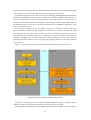
SOAP over HTTPS with basic HTTP authentication establishes the most common form of
secure communication for Web services. By using transport-level and network-level technologies
such as SSL/TLS and IPSec this could also constitute security communication. For example the
point-to-point transport-level security model allow messages to go though SOAP intermediary
node until they reach the destination, and the SOAP header and body possibly add/deleting header
blocks by the trusted intermediaries. The transport-layer security needs to be terminated at each
intermediary and the unauthorized intermediary could not reestablish the security information.
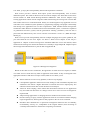
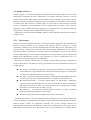
Figure 2.6 shows this situation.
Figure 2. 6 Point‐to‐Point Security Model
However, Web services will need an application-layer security for the situation intermediary
cannot access or modify some parts of message. The end-to-end security model is possible to
secure the entire conversation because the original message is secure independent of the
point-to-point protocols. The Figure 2.7 illustrates the situation of end-to-end security model.
Figure 2. 7 End‐to‐End Scurity Model
WS-Security provides the precise mechanism to establish this end-to-end security models.
SOAP Message Security has three key concepts: security tokens, signature elements and
encryption element. Base on those three concepts, WS-Security defines a SOAP Security Header
format that contains their sub elements to build the message convey from requester to services
19 endpoint. The architecture concept of WS-Security is that:
“Web services can be accessed by sending SOAP messages to service endpoints identified as
WS-Addressing endpoint references; these messages request specific actions from the service
provider, and often trigger SOAP-message responses (including fault indications). Within this
context, the broad goal of securing Web services breaks into two subsidiary goals: providing
facilities for securing the integrity and confidentiality of the messages, and ensuring that the
service acts only on message requests that express the claims required by the security policies. ”
(Weerawarana et al. 2005, p.273-274) [3]
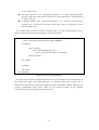
The WS-Security model is show in Figure 2.8.
Figure 2. 8 WS‐Security Model (Löwe 2008)[6]
In this model, the ‘Claims’ is a security statement of an subject; ‘Security Token’ is a
representation of security statement; ‘Subject’ – such as ‘Requestor’, ‘Security Token Service’ and
‘Web Service’, they are items about which the claims expressed; ‘Policy’ – Web service endpoint
policy, it is the claims and related information that the Web services require in order to process the
message. For example, if someone wants to send a request to Web service the requester might
have ‘claims’ regarding the message’s security properties like identity and authorization claims.
Then the WS-Security provides a way to represent the set of claims, the most common use is
‘security token’ and WS-Security also defines a standard XML format for convey those tokens.
The security token usually could come from trusted third party ‘security token service’, such as
X.509. After the request was accepted by Web service, the message should be encrypted according
to service requirements. These requirements are described as the service’s ‘policy’, particular
security policy.
WS-Security defines the standards format and using XML Scheme for mapping security tokens
to SOAP headers. There are three types of token common used and recognized as profiles in
WS-Security:
A username token (<wsse : UsernameToken>) is a claim on identity, the most basic
usage of security token. It could have a password, the requestor need correctly password
20
access to Web service.
An X.509 certificate (<wsse : BinarySecurityToken>) “is a claim regarding a binding
between a public key and its subject, endorsed by a trusted third party.” (Weerawarana et
al. 2005, p.275) [3]
A Kerberos ticket (<wsse : BinarySecurityToken >) is a claim that shows that the
requester own a session key contained in this ticket, which is authorized to access
particular Web service.
For example Table 2.5 shows an SOAP envelope which is a usage of WS-Security carries a
single username token asserting the requester’s security information:
<S : Envelope xmlns : S=”Sauer Danfoss”> Xmlns : wsse=http://docs.oasis‐open.org/wss/2004/01/...> <S : Header> … <wsse : Security> <wsse : UsernameToken wsu : Id=”…”> <wsse : Username>suaer</wsse : Username> </wsse : Security> … </S : Header> … <S : Body> … </S : Body> </S : Envelope> Table 2. 5 WS‐Security XML Example A security token could be a predefined username token or acquired from a trusted third party. In
the WS-Security model, this trusted third party is a Security Token Service (STS). One of
WS-Security specifications, the WS-Trust defines protocols and standard WSDL interface to let
requestor communicate with an STS. There are two interaction models of this requestor
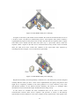
communicate with an STS: push model and pull model.
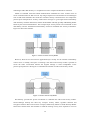
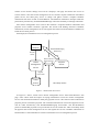
21 Figure 2. 9 Push Model of STS (Löwe 2008) [6] In Figure 2.9 describe a push model of trust establish. We could see the STS and Service was in
a ‘Scope of Trust’, the STS were authorized by Service. The requestor firstly need to obtains a
cryptographically signed security token from an STS, and after that the requestor make a request
to the Web service bound with the token. The other way is a pull mode, which is when the
requestor makes a request to the Web service associated with security claims such as username
token, the Web service then verifies that validation of the claim token from requestor by
consulting the STS. In Figure 2.10 we could see this pull model.
Figure 2. 10 Pull Model of STS (Löwe 2008) [6]
Regards the flexibility and interoperability of Web Service, the WS-Security need be designed
carefully. Because when you have a strict secure implementation, the policy and protocol used
might not be completely available in the entire platform so in some situation it may cause
interoperation problem. So the balance between flexibility and security is a challenge when
development a system and the developer should make their design wisely.
In this section we introduce the basic mechanisms that can be used to make secure
communication between Web service requestor and provider. A family of WS-Security
specifications has been defined to solve more complex security requirements, with regards to the
22 many aspects of Web service security.
2.5.2
Reliable Messaging
In quality of software field, how to ensure the reliability of transmit message in communication
channels is one of the key aspects. In internet world the communication channel are really
unreliable. You do not know when the situation occurs, such as connection break, messages fail to
be delivered or are delivered more than once, or messages might transmit in a wrong sequence,
and even worse the application crashed during sending message. Although there are some
messaging middleware products such as IBM WebsphereMQ, SonicMQ and MSMQ for ensuring
reliable delivery of messages, but messaging reliability is still a problem in Web services. Because
if Web service developers use above middleware products to address messaging reliability, the
problem will occurs at other side the developers cannot guarantee there is the consistent approach
for this adoption. The loose coupling and interoperability of Web services will not be satisfied.
L.Peter Deutsh, a noted computer scientist, he’s significant view point in software engineering –
the “Eight Fallacies of Distributed Computing”. Because the Web services essence is a distributed
application, certainly when design any Web services those fallacies should carefully be considered
in wisdom. There are three common fallacies related with Web services:
The Network Is Reliable – today most deployed Web services use Transmission Control
Protocol (TCP), even it is a highly reliable connection-oriented host-to-host network
protocol but TCP is only reliable in its TCP stack not in application layer. When
sending/receiving message that was acknowledged at the TCP layer, but the Web service
application crashed, the message could be lost from the perspective of the application.
Latency Is Zero – the latency between the distributed components impacts the reliability,
same as Web Services. The longer the latency, the potential of something going wrong is
greater.
There Is One Administrator – in the context of Web services, many administrators exist.
In normal case, you have administrators for each database, administrators for different
Web services components, and further the Web services which associated have their own
administrator. Therefore, you need a solution to recover from failures caused with
unavailable distributed components.
WS-ReliableMessaging addresses above issues and “defines protocols that enable Web services
to ensure reliable, interoperable exchange of messages with specified delivery assurance.”
(Weerawarana et al. 2005, p.46) [3] Basically, there are three types of assurances could use in
reliable message deliver:
In-order delivery – The messages are delivered in sequence of they were send.
At least once delivery – Each message delivered at least one time.
At most once delivery – Each message delivered at most one time, means no
duplication.
In WS-ReliableMessaging, those assurances could be combined. For example, if you want to
deliver the send message exactly one time, you could combine use at-least-once and at-most-once.
23 To realize this case, WS- ReliableMessaging defined as a set of SOAP Header extension elements
that enable a range of qualities of services for a Web service, from at-most-once through
exactly-once delivery assurances, preservation of message order, and duplicate detection.
“WS-ReliableMessaging protocols allow different operating and middleware systems to reliably
exchange messages, thereby bridging different infrastructures into a single logically complete,
end-to-end model for Web services reliable messaging.” (Weerawarana et al. 2005, p.47) [3]
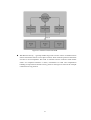
Figure 2. 11 Reliable Messaging Model
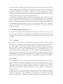
Above Figure 2.11 show the model of Reliable Messaging used in WS-ReliableMessaging. In
this figure we could see there are four roles are defined by WS-ReliableMessaging: Application
source and RM source on the sending endpoint, and Application Destination and RM Destination
at the receiving endpoint. The application code is running on the endpoint considered as
Application Source, it initiates the protocol by sending (logically) a message to the RM Source.
The RM Source is response for transmitting the message to the RM Destination role at the
receiving endpoint. The RM Source and RM Destination also are response for processing any
SequenceAcknowledgement messages transmit. Then RM Destination make a acknowledging
receipt of the message and delivering (logically) the message to the Application Destination role
which is considered as the application code that runs at the receiving endpoint. The
WS-ReliableMessaging Protocal is actually plays the RM Source and RM Destination roles, the
delivery assurances observes by the RM Destination aims to fulfill the specified delivery
assurance (At-Most-Once, At-Least-One, Exactly-Once, And Ordered). The Application Source
role is certain that the message has been reliably delivered only the RM Destination role has
received the massage at the receiving endpoint.
At the end, we could see that WS-ReliableMessaging provides a full range and simple solution
for reliable message communication. And it also provides the loose coupling necessary for Web
services to mitigate effect of the fallacies from internet or intranet.
2.5.3
Transactions
Today, the Web services business scenarios need the development of application that compose
multiple Web services associated together. Such applications can be complex and executing across
heterogeneous platform. Those loosely coupled distributed systems require significant reliability
than usual. So the transactions are a fundamental concept in building such reliable distributed
system. A transaction is a mechanism to ensure the associated Web services in an application that
24 can be agreed and guaranteed the coherent outcome of whole application. Transactions
traditionally have the following four properties:
Atomicity – The transaction completes successfully only if all the actions in that
application are completed, else it is unsuccessfully. It is called two-phase commit, in
which all the operations on data regarded as a unit either succeed or fail.
Consistency – Transactions ensure the consistent result for every participant and
preserve the correct transformation when the application states at completion.
Isolation – While transaction is executing, the intermediate are invisible for other
transactions. In a other words, the transactions appear to execute serially, to avoid
conflicting resources for the duration of the transaction, it will be locked to avoid other
transaction access until it is completed.
Durability – The outcomes will be maintained after a transaction successfully completes,
unless the critical failure occurs.
Above properties of transaction often referred to as ACID and are known as atomic
transactions.
In Web services environment, because the complex application is compose by multiple services,
the transactions is use to coordinating the results of multiple Web services. Different than classical
distributed system, the components of Web services are typically loosely coupled and distributed
across various independent systems. So for more flexibility requirement apply some of properties
of atomic transactions less strictly, such as flexible forms of outcome coordination process,
workflow, and outcome collaborations and so on. Therefore the Web services technologies
provides WS-Coordination that defines such a foundation coordination services framework that
could support additional protocols. WS-Atomic Transaction and WS-Business Activity provides a
set of common coordination protocols defined of atomic and business transaction protocols.
Generally, the WS-Coordination has three key elements:
“
A coordination context – This is a message element that is associated with exchanges
during the interaction of Web services. This coordination context contains the
WS-Addressing endpoint reference of a coordination service, in addition to information
that identifies the specific task being coordinated.
A coordinator service – This provides a service to start a coordinated task, terminate a
coordinated task, allow participants to register in a task, exchanged within a group of
participants.
An interface – Participating services can use the interface to inform them of an outcome
that all of the participants have agreed upon.
” (Weerawarana et al. 2005, p.48) [3]
In Web service transactions, the WS-Coordination is a general framework;
WS-AtomicTransaction and WS-BusinessActivity are two particular protocols that extend
WS-Coordination in specific situation. The Figure 2.12 depicts the WS-Coordination protocol
structures.
25 Figure 2. 12 WS‐Cordination Protocol Structure (Weerawarana et al. 2005, p.236) [3]
In above figure we could know the structure of Web services transactions protocol, and the
WS-AtomicTransaction and WS-BusninessActivity specifications define two processing patterns.
Normally the coordination architecture workflow is: firstly, WS-Coordination activation service
creates a new transaction activity and returns a context containing an identifier that distinguishes a
particular work scope; Second, the context is returned at activation and is passed along with the
Web services operation and identify the which operation to be contained within the transaction
scope; Third, the coordinate service receiving an register from the contained operations, and the
registration selects from the coordination protocols (WS-AtomicTransaction or WS-Busniness
Activity) that are supported; Finally, the protocol services associate with coordinate service
provides specific process pattern.
The different of two coordination protocols are:
WS-AtomicTransaction – typically handle activities that are short lived. Atomic
transactions provide two-phase commitment protocol which means all-or-nothing. The
Figure 2.13 shows an example of atomic transaction. If an activity is successful, all the
services result from operations performed during the activity are made permanent and
visible. In the other case, if the activity failed none of the changes will be made.
26 Figure 2. 13 Atomic Transaction Model
WS-BusinessActivity – typically handle long-lived activities. These are different from
atomic transactions and are not two-phase commit, which mean the protocol could allow
activities to be uncompleted. The result of internal activities could be visible before
others are completed. Because of these, mechanisms for fault and compensation
handling are important in business activity protocol. The Figure 2.14 shows the example
of business activity protocol.
27 Figure 2. 14 Business Transaction Model
In the end, transactions are the one of the most fundamental concepts in a Web services
environment handling complex reliable application processing. “Web Services transactions
provide a middleware service that augments the core Web services technologies of SOAP, WSDL,
and UDDI, enabling construction of a reliable computing environment.” (Weerawarana et al. 2005,
p.219) [3] Here we introduce the WS-Coordination with WS-AtomicTransaction and
WS-BusinessActivity architecture concepts and simple use scenarios to address the outcome
agreement issues.
2.5.4
File Transport Protocols (MOTM)
In this project, our project need has ability to send large amounts of binary data between requestor
and provider communication. Binary data usually is nontextual information data, likes audio/video
file, images, or executables files and so on. We know in Web services the communication is using
SOAP, but only character that XML allow are permitted. If we transform the binary data into
characters using the Base64 content encoding, we will met a problems such as encoding/decoding
between binary and characters take resource and message size increase because the transform.
Fortunately, in Web service Web have such solution – MTOM.
MTOM (SOAP Message Transmission Optimization Mechanism) provide a way to identify any
element information item in the SOAP message Infoset as a candidate for optimization. It defines
a mechanism for the binary data communication between service requestor and provide as SOAP
message attachments. And we also have XOP (XML Binary Optimized Packaging), it specifies a
way to serialize the various optimized elements and package them in the message to be
transmitted.
The binary file transport with MTOM provides a way to transmit binary file as SOAP
28 attachment. It is easily used in the development and with good reliability. The technical usage of
MTOM will be introduced late in the thesis.
2.5.5
Services Composition (BPEL Modeling Business Process)
Business Process Execution Language (BPEL) is a workflow language use to modeling business
process which is composed by multiple Web services. It provides a secure, reliable, transacted
interaction between distributed, heterogeneous applications. BPEL defined a formed and
standardized language format to describe Web services workflow. At the early time, BPEL
combine the advantage from IBM Web Service Flow language (WSFL) and Microsoft XLANG
build first specification version know as BPEL4WS in 2002. Later time in 2003, OASIS
standardized the BPEL4WS and renamed it to WS-BPEL. The least version 2.0 of WS- BPEL was
released in 2007 by OASIS.
WS-BPEL is an XML based programming language and it depends on various standard
technologies include: WSDL, XML schema, XPATH and WS-Addressing. WSDL is one of the
most important standards because WS-BPEL describes business processes as conversations
between various Web services and those Web services are described in WSDL. In other words,
WS-BPEL processes defines itself a Web Service with WSDL document. The WS-BPEL’s
architectural concept is defines a composition model aimed to addresses following issues:
Flexible integration – During business scenario business partners might exchange, and
the BPEL model has sufficiently expression to describe this kind business scenario.
More importantly, BPEL could rapidly adapt to changes in the services that BPEL is
interacting with.
Recursive Composition – BPEL offering a process as a standard Web service that enable
third-party could reuse existing Web services compose new service. The composition
has ability to provide different views to different parties, interworkflow interaction, and
increased scalability and reuse.
Separation and composeability of concerns – For the composeablity of the Web services
framework, “the business/service-composition logic should be decoupled from the
supporting mechanisms such as quality of service, messaging frameworks, and
coordination protocols. Such information should be capable of being layered on or
attached to different parts of the process definition if necessary.” (Weerawarana et al.
2005, p.316) [3]
Stateful conversations and lifecycle management – BPEL provide a clearly defined
lifecycle model with a workflow. Its means the BPEL could model multiple stateful
long-running conversations with the services that BPEL is interacting with.
Recoverability – In business scenario, the long-running processes normally have
potential error risk. BPEL also provide a built-in fault handling and compensation
mechanisms to deal with expected errors.
The BPEL business processes construct by the XML blocks which are nested scopes, it include
the information about external partners, declarations for process data, handlers for various
purposes and the activities to be executed. Table 2.6 shows an example of BPEL structure
scenario.
29 <process> <!– Definition and roles of process participants ‐‐> <partnerLinks> ... </partnerLinks> <!‐ Data/state used within the process ‐‐> <variables> ... </variables> <!‐ Properties that enable asynchronous interaction ‐‐> <correlationSets> ... </correlationSets> <!‐ Exception handling ‐‐> <faultHandlers> ... </faultHandlers> <!‐ Error recovery – undoing actions ‐‐> <compensationHandlers> ... </compensationHandlers> <!‐ Concurrent events with process itself ‐‐> <eventHandlers> ... </eventHandlers> <!‐ Business process flow ‐‐> (activities)* </process> Table 2. 6 BPEL Structure Example
In BPEL, <partnerLinks> declares the roles which related Web services process. The related
partners’ process links with their WSDL endpoint and the messages communication though those
links.
“Data in BPEL is written to and read from lexically scoped, typed variables. The values of these
variables are either messages exchanged between the process and its partners.” (Weerawarana et al.
2005, p.318) [3] And business processes defines stated interactions of messages between partners,
its means the variables store this state could persisted for long running interactions.
The activities in BPEL process have two types: structured and basic. The basic actives are like
data manipulation or inbound or outbound Web service interactions. And in structured activities
the business logic interaction was defined by the process. Table 2.7 shows the ways that BPEL
provided to deal with those activities:
Basic Activities
Structured Activities
<invoke>
<receive>
<assign>
<reply>
<throw>
<terminate>
<wait>
<sequence>
<switch>
<pick>
<flow>
<link>
<while>
<scope>
Table 2. 7 BPEL Activities <correlationSets> defines mechanism that enable the user to create an instance encompassing
multiple receives. The sessions could become complex when messages come over various
endpoints and mutually interleaving. Correlation set define such correlated properties and binding
30 properties with specially marked messages when sending/receiving them. Correlation set enables
validation of the business logic in ensuring that certain pieces of data have the same value in each
instantiation of a process.
In BPEL, <faultHandles> and <compensationHandles> provide a built-in model to hand
exception behavior. Fault handles in the model is use to catch faults and reverse partial and
unsuccessful work, it is actually a build-in model switch from doing regular work to repairing an
exceptional situation. The <compensationHandles> is use to handler reverses completed activities,
the compensation handler invoke after successful completion of its associated scope.
From above short introduction of BPEL we could know that it provides the full power of
established workflow concepts coupled with recursive composition and dynamic binding to
business partners. It defines an orchestration way to recursively use Web services composition,
and it is integrated into the Web services stack and natively built for a dynamic, networked SOA
environment.
2.6 Apache Axis2/C Web Services Frameworks
In the above sections we introduced the most important technology aspect of Web services. Web
services frameworks provides a structure for integration and a foundation for Web services
protocols that will support the needs of implementation. Different frameworks support in different
development platform and specific Web services protocols. For example, in Java we have Apache
Axis2, X-Fire and in PHP we have WSO2 WSF/PHP and so on. This section we will describe
general information about some Web services frameworks and the motivation about which one we
choose in our project.
In this thesis the Sauer Danfoss Company prefer the project develop platform suitable for their
existing products, and PLUS+1 software platform is developed by Delphi and C++. So the Web
service framework better support C platform and they also want the framework with good
implement ability, extensibility, and transportability. Base on those requirements we have Table
2.8 about the candidates Web services frameworks for C:
Name
Platform
Specification
Protocols
Apache Axis2
Java/C
WS-ReliableMessaging,WS-Security,WS-Atomi
cTransaction, WS-Addressing, MTOM,
WS-Policy, WS-MetadataExchange, WS-Events,
WS-ReliableMessaging, WS-Events
SOAP1.1,
SOAP1.2
MTOM,
WSDL2.0,
WSDL
gSOAP
C/C++
WS-Addressing, WS-Discovery,
WS-Enumeration, WS-Security
SOAP,
XML-RPC,
WSDL
MTOM
WSO2 WSF/C
C
WS-Addressing, WS-Policy, WS-Security,
WS-SecurityPolicy, WS-ReliableMessaging,
WS-Events
SOAP,
WSDL 2.0,
WSDL
MTOM
Table 2. 8 Candidates Web Services Frameworks for C 31 From above table we choose three well known Web service frameworks that support C platform.
They are significant supporting C platform with good implementation ability and well
maintenance by their developer.
Apache Axis2/C is “a Web services engine implemented in the C programming language. It is
based on the extensible and flexible Axis2 architecture. Apache Axis2/C can be used to provide
and consume WebServices. It has been implemented with portability and ability to embed in mind,
hence could be used as a Web services enabler in other software.” (Apache Axis2/C)[8]
The gSOAP toolkit is “an open source C and C++ software development toolkit for
SOAP/XML Web services and non-SOAP C/C++ XML data bindings. The toolkit analyzes
WSDLs and XML schemas (separately or as a combined set) to map the XML schema types and
the SOAP messaging protocols to easy-to-use and efficient C and C++ code.” (gSOAP) [9]
WSO2 Web Services Framework/C (WSO2 WSF/C) is “a standards compliant, enterprise grade,
open source, C library for providing and consuming Web services in C. WSO2 WSF/C is a
complete solution for building and deploying Web services, and is the C library with the widest
range of WS-* specification implementations.” (WSO2) [10]
At last we choose Apache Axis2/C for this thesis because it is developed by well known Apache
organization and it has been through a long time evaluation with mature implementation. And
Apache Axis2/C developed as an extension for Apache Axis2/Java, so it has a good extensibility to
make application transport from C platform to Java platform or both platform frameworks could
easily associate with each other. The detail technology information about Apache Axis2/C will
introduce later in this thesis.
2.7 Project Design Overview
In this section we will introduce the project design overview in Web services architecture. The
illustration will show how the Web services protocols enable secure, reliable and transaction
interaction in project scenario.
2.7.1
Sauer-Danfoss PLUS+1 GUIDE Update Web Service
‘PLUS+1 GUIDE’ is Sauer-Danfoss’s main software product for embedded software development
platform. Every year it has 2 release patches and they want build-in auto-update functionality by
using Web services.
Scenario Description
In this project, a software platform could secure access to PLUS+1 update Web service to get
patches and update to the last version automatically. Here assume we have three servers:
Sauer-Danfoss UDDI server, PLUS+1 update server and user license management server. The
interactions in this scenario are: first, PLUS+1 client opens the software platform with valid
license or user account, the platform will connect to the Sauer-Danfoss UDDI server and request
the update services with license or user account attachment; Second, the UDDI server pass the
license attachment information to license management server to verify the validation; Third, with
valid license or account the UDDI server will bind the client software platform with PLUS+1
32 update server. Forth, the update server will check the version information from client platform and
transmits suitable patches back to the client platform to install. Finally, the update service process
will shut down through rapid implement forth step until client platform become last version.
In this scenario, the client’s account and license should be secured convey to user license
management server. With this requirement the security of transmission will be the primary
consideration. The binary data file of patches transport between client software platform and
update server also is an important aspect of this scenario.
Architecture
The interactions among the service parts are shown in the following Figure2.15. This figure shows
the interaction between the client software platforms with Sauer-Danfoss UDDI server: request
update service from Sauer-Danfoss UDDI server and bind to update server after verify license
validation. Also the interactions between Web services servers: passing license to license
management server and services deployment between Sauer-Danfoss UDDI server and update
server. The thin black arrows represent interactions which do not belong to Web services
interactions, in Figure 2.5 they are database requests from server to databases.
Software Platform Update process Request service Binding Verify License Management Server License Sauer‐Danfoss UDDI Server Service PLUS+1 Update Server Queue service information UDDI Queue license Database
information Queue patch information S‐D mian Database
Figure 2. 15 PULS+1 Update Architecture Overview Above illustration can be divided in two parts: license verification part and update process
completion part.
Next two figures are shown the Web services protocols used among the interaction in those two
33 parts. Figure2.16 shows the license verification part.
Software Platform WS‐ReliableMessage WS‐Security WS‐Authorization License Management Server WS‐Security Sauer‐Danfoss UDDI Server Queue license information S‐D mian Database Figure 2. 16 License Verification Part
In above figure, we could see the WS-Security make sure the security communication between
software platform and Sauer-Danfoss UDDI server. Specially, WS-Authorization allows use valid
user account or license token connect between requestor and provider. Also, the WS-Security
taking place between UDDI server and license management server enable the important message
communicated under security environment.
The messages communicated in this figure includes: client software platform request update
service information; user account and password information; license token information and after
successful verification returned the update service binding information.
Next Figure 2.17 represent update process completion part:
34 Software Platform WS‐ReliableMessaging WS‐Security MTOM WS‐ReliableMessage WS‐Security WS‐Authorization WS‐Frederation Sauer‐Danfoss UDDI Server PLUS+1 Update Server Queue service Queue patch information information UDDI S‐D mian Database
Database
Figure 2. 17 Update Process Part
After successful license verification, Sauer-Danfoss UDDI server return update service binding
information back to client software platform. The client software platform was successfully
binding with the update server. The WS-Federation placed between Sauer-Danfoss UDDI server
and update server directly provides update service for trusted third-party user – client software
platform. In another word, the WS-Trust relationship built between client software platform and
update server. The communication messages are using WS-ReliableMessaging protocol transmit
between them under WS-Security environment. MTOM protocol provides a way to transport
binary patch files by using SOAP message attachment.
The messages in this interaction include: platform version information sent from client software
platform; binary patch files back from update server; query message between update server and
Sauer-Danfoss database.
This design overview represented an illustration of Sauer-Danfoss update service in Web
services architecture. It describes the Web services message interactions between the requestor and
provider, and the Web services protocols that are used to improve the service performance.
In this section we introduced a brief design illustration by Web services architecture to address
the requirements from Sauer-Danfoss. The Web services technologies that are used in the
architecture ensure the reliability and security of the process. Some of the design may not
appropriate and will be modified in future implementation.
35 3. Design Description
In this chapter we will introduce the design details and the implementation architecture of the
project system. First section the requirement specification describes the system requirement in
specific, and then following sections shows Sauer-Danfoss PLUS+1 update Web Services system.
The structure of the system will be represented in a detail level, what the client side and server
looks like and how the requestors communicate with service providers. The interaction between
the server and client will depict in this chapter. We will also use a model that shows the massages
passing and the workflow of the program.
3.1 Requirement Specification
This section describes the requirements and perspective of the Sauer-Danfoss’s PLUS+1 update
Web Services system. It will define a user-case model for the system and describe the ideas of
how to design Web Services system features according to the requirements. The software system
development of this thesis should accord with these requirements, and fulfill the goals and criteria.
3.1.1
System perspective
This Web Services system provides a solution for a software development platform “PLUS+1
GUIDE” which is Sauer-Danfoss’s main software product. It has patches release for the software
development platform every year. The thesis main task is to implement a procedure to automatic
find new patches and update files, and it also has a new patch notification function for the user.
Beside the main task there are some subtasks which include finding the way to report errors,
collect relevant files, gather useful information and so on. We will introduce them in following
sections.
The Web Services system should use the most proper way to implement automatic software
updates; also the system should provide an easy way to deploy service and implement client.
Figure3. 1 System Perspective 36 In Figure 3.1 we represent a brief structure of the system. The system has a client side
‘Plus_Client’ which is the user build-in the PLUS+1 software develop platform. There are two
remote servers: “Plus_UDDI_Server” and “Plus_Update_Server”; the UDDI server provide a
function so the developer could publish new Web Services and customer could search and bind
particular existing services; “Plus_Update_Server” is the auto-update function server, it uses to
return the related PLUS+1 software development platform update patches information to the client
side.
3.1.2
System Requirements
The main function of this Web Services system is new patches auto notification and update for the
“PLUS+1 GUIDE” development platform. The others functions are base on the main function and
support by Web Services technology.
The requirements of the system see the Table 3.1:
Requirement Description
Type
R1
Find the best way to implement automatic software updates.
Essential
R2
Find the best choice of application server and database. And also how to
best update the contents of the database when new software is available.
Essential
R3
Implement automatic updates system, beginning with notifications.
Essential
R4
Find the best procedures and methods to use when deciding to add new
functionality to the Web Service.
Essential
R5
Find and implement a method to push out important safety related
information to users.
Essential
R6
Find and implement a method to automatically collect usage patterns from
users who allow this functionality.
Desirable
R7
Find and implement a method allowing users to report errors, and
automatically collecting and sending in relevant files and information.
Desirable
R8
Find and implement a way to give each user an account, thus allowing some
users to download specific files intended for that user only.
Opt-in
R9
Find and implement a method for any user to upload files to us. Uses could
be debugging, or to add their project to our regression test suite.
Opt-in
R10
Find and implement a method for any user to share his own and other users
code and other helpful files like documentation, tutorials etc.
Opt-in
R11
User collaboration tools, forums, instant messaging between users and
possibly the helpdesk.
Opt-in
Table 3. 1 System Requirements Table 3.1 shows the system requirements, there are three types of requirements: “Essential”,
“Desirable” and “Opt-in”. The “Essential” means Sauer-Danfoss think the requirements is
something they must have in the Web Services System of this thesis; “Desirable” shows that they
want those requirements as a part of the system; “Opt-in” shows the requirements that we could
have in this thesis as optional function. Anyway in this thesis we try to fulfill the listed
37 requirement as much as possible, some of “Desirable” and “Opt-in” parts will be given the
solution advices instead of the detail implementation.
We could see there are five “Essential” requirements; R1, R2, R3 build the main function of the
system; it provides an implementation to establish a client/server structure and get the patches
update the software platform automatically. The R4 is a kind of supporting requirement, it restrict
the system performance and system structure in specific requirement. R5 is another system
function requirement, and it defines an operation that could transmit binary file as attachments
between client and server. In this thesis those “Essential” requirements will be fully achieved, and
they are the main composition and the kernel of this thesis program.
R6 and R7 are the “Desirable” requirements. They define the functions that are important for
the PLUS+1 update Web Services system. Sauer-Danfoss want them to be part of the system and
in this thesis we also give them the attention as “Essential” requirements.
The other requirements, those “Opt-in” ones, Sauer-Danfoss think they are not the must have
part of the system. They are very happy to see if there are solutions for them otherwise they want
some advises for those requirement as future work.
3.1.3
Use-Case Specification
In this section we will introduce with the Use-case specification of the system. It will help the
reader understand the system structure more easy and show the illustration of the system functions.
Also it describes the Use-Case model in detail: we define a goal-oriented set of interactions
between external actors and current system. By describing the features of the system as Use-Cases
model makes it easier to mapping system functions with requirement. Following Figure 3.2 shows
the Use-Case as diagram:
38 Figure3. 2 Use‐Case diagram of the system We could see the Use-Case diagram in Figure 3.2. There are “Client Side” and “Server Side”,
those two parts that constitute the Web Service architecture. And there are five Use-Cases in the
client side represent the function of the system. Each client operation link to different service
operations, and there is client side operation “download & install patch” indicate after receive the
return massage from server the client start download & install patch.
By individually analysis of each use-case we could more clearly understand the system function
interaction and requirements consistent. In the Table 3.2, Table 3.3, Table 3.4 and Table 3.4 we
will explain the four main functions in detail and describe the requirement composition:
Use Case
Plus Update
Goal
Automatic update the software development platform.
Related Requirement
R1, R2, R3
Pre-condition
Bind plus_update web service from plus_UDDI server;
Success link to plus_update server.
Post-condition
Receive patch information and download address from server;
Or receive “least” massage from server.
Flow of events
1. Start plus_update_client process;
39 Alternatives
2.
3.
4.
5.
6.
Access to plus_uddi_svc bind plus_update_svc server;
Link and send current version information to plus_update_svc;
Receive return massage from plus_update_svc;
Download & install patch;
Repeat 3 – 5step until receive “least” massage from server.
1.
2.
3.
4.
Throw error when link to plus_uddi_svc failed;
Throw error when link to plus_update_svc failed;
Throw error when return massage is invalid;
Terminate process when receive “least” massge.
Table 3. 2 Plus Upadate Use‐case Specification Use Case
Publish Service
Goal
Publish new web service and discover exist web service;
List all the deployed web service to client;
Bind specific web service to client.
Related Requirement
R4
Pre-condition
Service files has been put in axis2/c service path and deployed.
Post-condition
Service succeed publish in plus_uddi_svc;
Service could bind by client.
Flow of events
1. Deploy service files in axis2/c;
2. Access to plus_uddi_svc and set operation;
3. Base on operation get return massage from server.
Alternatives
1.
2.
3.
4.
Service files deploy failed, cause server link error;
“bind” operation return target web service information back to client;
“list” operation return all the deployed web service as list to client;
“add” operation add new web service information which from client
into UDDI database;
5. Invalid operation request from client, then return an error massage.
Table 3. 3 Publish Service Use‐case Specification Use Case
Plus File Trans
Goal
Transmit attachment file by Web Service massage pack in both client and
server side.
Related Requirement
R5, R6, R9, R10
Pre-condition
Target file exist in path.
Post-condition
File transmitted in both client and server side.
Flow of events
1. Succeed access to plus_file_trans_svc;
2. Client send target file to server as attachment by Web Service
communication massage;
3. Server parse file from receive massage and store in local memory;
4. Server send receive file back to client in same way;
5. Client parse file from server and store in local memory.
Alternatives
1. Target file miss, then process will return an error massage;
2. Transmission error, throw out file parse error;
40 3. Access to plus_file_trans_svc failed.
Table 3. 4 Plus File Trans Use‐case Specification Use Case
User Service
Goal
Consisted by multiple services for “PLUS+1 GUIDE” software
development platform customers, it enrich the system function which let
user more easily to use.
Related Requirement
R8, R9, R10, R11
Pre-condition
Services deployed succeed.
Post-condition
Customers are access service succeed.
Flow of events
1. Start “PLUS+1 GUIDE” succeed;
2. Choice service in software and following the instruction use different
service.
Alternatives
1. “PLUS+1 GUIDE” start failed;
2. Web access failed.
Table 3. 5 User Service Use‐case Specification In the above Table 3.2, Table 3.3, Table 3.4 and Table 3.4 are describe detail of the Use-case.
From those tables we could clearly see: the goal of the use-case which let people know what this
use-case is for and the function operations of the system; The “Related Requirement” depicts
which requirement fulfilled by the functions, the reader could easy understand how the task
achieved the requirements in thesis; Pre and Post condition indicate the what should be done
before and the state after the process; “Flow of events” and “Alternatives” describe the interaction
sequence during the process running.
The Use-case model introduces the functions of PLUS+1 update Web services system in a
high-level. It use a goal-oriented model; describing the operations in the system and interactions
between client and server. Also it illustrates a brief workflow of program function and how the
requirements were fulfilled.
3.2 Architecture and Design
This chapter provides a comprehensive architectural overview of PLUS+1 update Web services
system. It shows the logical view of the Web Service system for the software development
platform. And this chapter will include an overview of all the components in this Web Service
system. We will also depict the interaction between the components by functions and in the end
we will brief shows the system database structure.
3.2.1
System Components
In the PLUS+1 Update Web Service system, we initially assume there are two clients, three
servers and two databases. They composed the critical function and fulfill the requirements of the
User-case model. In Figure 3.3 we could see the components of the system.
41 Figure3. 3 System Components From above Figure 3.3 we could clearly see the composition of the system, and each of
components is play the function role:
Plus_Client – The client for software platform automatic update, it consisted by three processes:
bind the plus update service address from plus UDDI service; get update
information from plus update service; download and install patch. It will repeat
those three processes until the software update to last version.
Plus_File_Trans_Client – This is the file transmit service client, it provide a solution for the
service which need binary file transport. It is a simple client that just sends an
object file as an attachment with Web Service massage to the server and receives
the file sent back from plus file transmit server.
Plus_UDDI_Server – The server side of the plus UDDI service, it provide multiple operation of
UDDI service. This server with multiple function entrances which is implement by
service skeleton.
Plus_Update_Server – This server provide the service for the client to search the patch
information. It will return the patch download address and target version
information if the client software platform is not the last version, otherwise it will
return “least” massage.
42 Plus_file_Server – This is the server side of the plus file transmits. The server has only one
function which get the binary file from plus file transmit client and send this binary
file back to the client.
UDDI_Database – This is the database for plus UDDI service. It stores the information about all
the deployed Web Service; include the service address, service operation and
operation parameter.
Update_Database – The database of the plus update service stores the information about the
“PLUS+1 GUIDE”. The user could query the version information and it will
provide the result about patch download address, patch version and so on.
3.2.2
System Interaction
The interaction between the client and server is the most important architecture of this thesis,
because the interaction determined how the Web Service system components collaborate together
to achieve the requirements function. This section describes the interaction between the Plus client
and service, also the way service connect database get the data. It includes what parameter
massage client send to service; the server return massage composition; the database return
information and so on. And we will introduce them by individual service; there are two
client/server constructs: Plus Update Process and Plus File Transmit Process.
Plus Update Process:
This process is the critical function of the Web Service system, it provides a solution to
automatically discover the new patch from the server and install until least version. Here we will
focus on the massage interaction between system components; in Figure 3.4 we could see the
interactions in system components:
43 Figure3. 4 Interaction of Plus Update Process
The numbers indicate the interaction between the components:
(1) Plus_Update with Plus_UDDI_svc:
Forwards:
z String operation : invoke the specific operation of services;
z String param1: parameters of operation;
z String param2: parameters of operation.
Return:
z String[] result: the return massage base on the invoked operation.
(2) Plus_Update with UDDI_database:
Forwards:
z String query_str: the MySQL database query sentence, base on invoked operation;
Return:
z String db_ret: the result of the query.
(3) Plus_Update with Plus_Update_svc:
Forwards:
z String version: current version of the client software development platform;
Return:
z String address: the download address of the patch file;
z String version: the version update to.
(4) Plus_Update_svc with UpdateDatabase:
Forwards:
z String query_str: query is there any patch for current client software;
Return:
z String[] result: the related information of the patch file.
44 Plus File Transmit Process:
This process is the solution for file transmits as an attachment with Web Service massage passing.
There is only a simple client/server construct, and the server only has one operation as default:
Figure3. 5 Interaction of Plus File Transmit Process
In Figure 3.5 we could see there is a simple interaction between the client and server: the String
file_name is the file name of the attachment file; Data file_date_hanlder is the file data
information. When the massage arrive the target the process will parse the file programmatically
to the file type.
3.2.3
Database Structure
This section depicted the database structure of the Web Service system. In this system all the
databases are on the server side and directly accessed by the server. There are two databases to
store the different information: one of them is used to store the UDDI information, which include
the information of the deployed Web Services of the system; the other one is used to store the
“PLUS+1 GUIDE” patch information. In following we will introduce them individually.
Plus UDDI Database:
This database mainly stores the information about the deployed Web Services. From this database
the users could find the information of specific service and use the information to do further work.
At first we create two tables to store the related date which include Web Services addresses,
operations, and operation parameters and so on.
Uddi
Index
Column name
Type
Describe
1
serviceName
varchar(100)
The name of the Web Service.
2
address
varchar(255)
The end point address of the Web Service.
Table 3. 6 Table uddi of Plus UDDI Database
uddi_op
Index
Column name
Type
Describe
1
serviceName
varchar(100)
The name of the Web Service.
45 2
operation
varchar(100)
The operations of the Web Service.
3
parameter
varchar(100)
The operation parameter of the Web Service.
Table 3. 7 Table uddi_op of Plus UDDI database
In Table 3.6 and Table 3.7, we could see the column name and type of the tables. Those two
tables store the Web Services name, end point address, operation and operation parameter. That
information is enough to discover a new or existed Web Service.
Plus Update Database:
The information about the patch file is very important for this system. Here we use this database to
store the related information about the patch files. The user could get the general information
about the patch file from this database, which include release date, patch file download address
and so on. Base on this database the user could easily get necessary information of the patch file.
Updatefiles
Index
Column name
Type
Describe
1
releaseDate
Date
The release date of the patch file.
2
typeOfFile
varchar(50)
The type of the files. Etc: patch, code…
3
version
varchar(50)
The version of the current version.
4
updateVersion
varchar(50)
The version of the update to version.
5
fileAddress
varchar(255)
The address to download the file.
6
MD5code
varchar(50)
The code use to verify the download completeness.
Table 3. 8 Table updatefiles of Plus Update database
In Table 3.8 we could see the information about the patch file. For example, now we have a
patch file release 2009-10-01, typeOfFile is patch, version is 1.0, updateVersion is 2.0, fileAddress
is http://www.test.com/test.exe and MD5code is 1213dadfe. Once the server query is there any
patch file suitable for version 1.0, then the database will return the information about this patch to
client. The client could use the file download address to download the patch file and install to least
version.
3.3 Implementation
This section describes the implementation of the PLUS+1 update Web Services System. We will
introduce file structure, methods and massage interaction between the client and server. Also we
will depict the most important technologies which used in the thesis, include how to use Web
Service framework construct the client/server, how to deploy Web Service, how the build/ parse
massage of communication and so on.
3.3.1
Web Service System for Project
This section we will focus on the file structure of the Web Service system. The implementation of
the system includes client and service part. Those two parts are composed by various codes to
46 achieve the functions.
In this thesis we use C language to implement the programming part, and Apache Axis2/C
which is a very powerful Web Service framework in C language. The structure of the code will
follow the Apache Axis2/C rules. In general there are two different service contractures, one kind
of service with multiple operations, and the another one only with single operation. The difference
of those two structures is service entrance implement. Because the single service structure only
uses one by one operation, we simplified the code structure without include client stub. Although
the structure is simplified, it very easy convert single operation handle to multiple operation
implement.
Figure 3.6 depict the file structure of whole system:
Figure3. 6 File Structure of the Web Service System
In Figure 3.6 we could clearly see the file construction of the Web Service system. There are
client and service part which are located the client and server. And there are small differences
between them, we mention it in above paragraph, one of them has client stub but others do not
have. Cause we simplified the structure of single operation service.
The file structure represent how to turn the design pattern to products, we could clear see the
system components and how the components connect together to achieve the system functions.
3.3.2
System Functions and Interaction Specification
Function to be realized is the goal of the project. In this section we will present how the “PLUS+1
GUIDE” Web Service system functions work. We will introduce the system functions in pieces,
from the functions code structure to function interaction between client and server. And we will
describe the workflow of the client and server. The reader will more clearly understand how the
system works.
In this implementation specification we will also introduce the Apache Axis2/C usage. Include
47 how to use Axis2/C operations to build the system and working flow of the system running.
The “PLUS+1 GUIDE” Web Service system has following parts:
(a) Plus Update Function:
This part achieves the requirement of automatic discovering the update patch for “PLUS+1
GUIDE” software development platform. To achieve this function we build two services:
Firstly, UDDI service which is one of the Web Service architecture aspects. This service
provides a service for Web Service publish and discover. It is like a telephone yellow page book.
Through the service the system administrator could implement web service and publish them at
the UDDI server. The client user can request the UDDI server and list all the published web
services. And the user could bind specific web service by correct web service name on the server.
For one of the Web Service technology aspect, UDDI provides a powerful way that the user could
search services at development time and also dynamic binding services.
Second, plus update service. Base on UDDI service we could discover and bind the plus update
service from UDDI server. In this service, we first use the UDDI service return information and
connect to plus update server, then send the patch request massage to server side. The server will
return the patch information back to client, if client PLUS+1 software platform is the least version
the client will close the update process, otherwise the client will download and install the patch
file and repeat above flow until least version. UDDI service provide a Web Service architecture
aspect used to implement Web Services, and plus update service is give a function to automatic
discover and update the patch of the PLUS+1 software development platform.
We will introduce the details of those services; firstly in Figure 3.7 we could see the functions
of the UDDI service:
Figure3. 7 Function Specification of Plus Update
48 Figure 3.7 depict the most important functions of the plus update procedure working flow.
There are the client side and the server side, those two parts communicate though SOAP message.
We do not discuss how to use SOAP communication but that is the information data convey
though SOAP.
In client side start with main method, we start plus_uddi_svc firstly. We could see there are
three operations of the UDDI service, each operation target by a stub method. User could call
different method by parameter. Those three stub method will invoke different service operations in
server side. The server parse the massage pack send from client, the service skeleton will invoke
specific service method in the server side. There is a special method plus_svc_database_imp
which use to query database by SQL sentence. After the service process the operation, the skeleton
will send the return massage pack back to client stub. When client stub receive return massage
pack, it will call a method de-build the pack and process the information.
After plus UDDI service gets plus updates service information, the client start plus_update_svc
method to get the patch information from server. Cause the plus_update_svc only has single
operation, so we skip the multiple operations stub. The client send current software version to
server side. The server skeleton invokes axis2_plus_svc_greet method and starts plus_update
service operation. The server first parses the current client software version information and query
the database is there any patch for client. After that, the server pack and send the database result
back to client. The client de-builds the return massage: if the return massage is available patch
version and the download address then the client will start plus_download_update method to
update the software. After install the patch the system will do the plus_update_svc again, until
update the software to least version; otherwise, if the return massage is ‘least’ the system will end
the plus update operations.
Following is an example of the plus update function working flow:
Precondition:
“PLUS+1 GUIDE” current version: 1.0
Patches: version 1.0 – 1.1
version 1.1 – 2.0
Working flow:
z Start main() method, set UDDI service operation “bind”, parameter “Plus_Service”,
service address “ http://localhost:9090/axis2/services/Plus_UDDI_svc “ and version
“1.0”;
z Call method plus_uddi_svc(op, par1, par2, uddi_addr);
Initial Axis2/C web service environment setting and build request massage by
method build_om_programatically(env, operation, param1, param2);
Create client stub by operations, cause we set operation “bind” so system call
method axis2_plus_stub_bind(stub, env, node);
Stub send the massage pack with operation name and wait the receive return
massage, method: axis2_svc_client_send_receive_with_op_qname(svc_client,
env, op_qname, node);
Plus UDDI server initials the Axis2/C web service environment setting and the
49
z
z
z
z
z
z
z
z
skeleton receive the massage pack from client side;
Server skeleton parse the massage pack and get the operation name “bind”, skeleton
invoke the method axis2_plus_UDDI_bind(env, node);
Operation parse the operation parameter “Plus_Service” from massage pack;
Set SQL string and call method plus_svc_database_imp(db_query_str) to get
the “Plus_Service” web service information from plus ‘uddi’, ‘uddi_op’
databases.
Build the return massage pack by method build_bind_response(env,bind_om)
and send it back to client;
Receive return massage pack from server, pass the return massage pack to
plus_uddi_svc and call the method debuild_om_by_operation(env,ret_node) parse
the return information;
Get the “Plus_Service” address from UDDI, and return it to main() method;
Main method start plus update by method plus_update_svc(update_addr,version)
with the address from UDDI service;
Initial Axis2/C web service environment setting and build the request massage
pack by method build_om_request(env,current_version) with current version
“1.0”;
Call method axis2_svc_client_send_receive(svc_client, env, payload) to send
the massage and wait return massage;
Plus Update server initials the Axis2/C web service environment setting and the
skeleton receive the massage pack from client side;
Server skeleton invoke the method axis2_plus_svc_greet(env, node);
The axis2_plus_svc_greet method set the SQL string and parse the massage
pack get current client software version “1.0”;
Call method plus_svc_database_imp(db_query_str) to get software patch
information from plus ‘updatefile’ database. Patch target version: ‘1.1’ ,
download address ‘address’;
Build the return massage pack by method build_plus_update_response(env,
version, address) and send it back to client;
Plus update client receive return massage pack from server, parse the return patch
information by method process_om_response(env, ret_node);
Get the patch information: target version ‘1.1’, download address ‘address’;
Start patch download and install procedure to update software to target version by
method plus_download_update(update_version,addr). After that the software current
version is ‘1.1’;
Repeat does plus update service until the current software version is ‘2.0’, when the
plus update service returns massage: target version ‘least’; download address ‘least’.
Release the entire Axis2/C environment setting and shut down the system.
(b) Plus File Transmit Function:
50 The plus file transmit function achieve the requirements which need files communication between
client and server side. It provides a general solution for all the similar functions.
To realize the function we use a Web Service aspect technology MTOM (Message Transmission
Optimization Mechanism). Under Axis2/C web service framework, MTOM allows the user to
send and receive binary data with SOAP messages. By using MTOM it is much easier to
manipulate the function with file communication. The technology detail we will introduce detail in
the following section. In this section we only introduce how to use MTOM to implement a web
service file transmit service.
In this plus file transmits service, we defined a target file ‘axis2.jpg’ in the client side. The
service destination is client send this image file to server; after server receive and store the target
file in memory, the server send it back to client. This is two direction file communication service,
both client and server could send and receive. Although we do the file transmits in two directs, but
though by modifying code we could easily get one direction file passing server. The reason for
providing plus file transmits service is to give the user a general solution of web service with file
communication.
Figure 3.8 represent the main function interaction between the plus file transmit service:
Figure3. 8 Function Specification of Plus File Transmit
In Figure 3.8 we could get the idea of function interaction between the plus file transmit. People
could get a rough idea of how the client and server communicate to each other.
Firstly, the plus file transmits service procedure starting with main method. After system setting
51 web service environment options the process build the request massage, in method
build_om_programatically it use axis2_data_hanlder to transform the target file data to xml
massage. Then the client send the request massage pack to server, the pack include the information
of the file name and file data. The method axis2_svc_client_send_receive send the massage pack
out and wait the return massage.
When server skeleton receive the service request from client, the method plus_svc_invoke
invoke the axis2_mtom_mtom function to process the massage from client. The
axis2_mtom_mtom
will
parse
the
file
name
information
and
use
an
axis2_data_hanlder_input_stream to extract the file date from the request massage. After that, the
server builds the response and sends received file back to the client.
After the client get the return massage and extract the file data stored in local memory, the
system release the web service environment setting and close the service.
Following is an example of the plus file transmits function working flow:
Plus File Transmits Function Working Flow Example:
Precondition:
Target file: “resources/axis2.jpg”
File type: “image/jpg”
Save as name: “test.jpg”
Save folder: comparative path
Working flow:
z System start the process and set above parameter to variables;
z Initial Axis2/C web service environment setting, enable file transmit module MTOM:
axis2_options_set_enable_mtom(options, env, AXIS2_TRUE);
z Engage addressing module by method axis2_svc_client_engage_module(svc_client, env,
AXIS2_MODULE_ADDRESSING);
z Build the SOAP request massage payload by method build_om_programatically(env,
image_name, to_save_name, optimized);
In payload building, create axiom data handler to transmit attachment file, we use
methods: axiom_data_handler_create(env, image_name, "image/jpeg") and
axiom_text_create_with_data_handler(env,
image_om_node,
data_handler,
&date_om_node);
z Send the request massage and wait to receive return massage by method
axis2_svc_client_send_receive(svc_client, env, payload);
Plus file transmits server initials the Axis2/C web service environment setting and the
skeleton receive the massage pack from client side;
Server skeleton invoke the method axis2_mtom_mtom(env, node);
Parse the massage pack, first get the file name then get data handler from
client.:axiom_text_get_data_handler(bin_text, env);
After that server use axiom data handler operation get file data :
axiom_data_handler_get_input_stream(data_handler, env);
52
z
z
3.3.3
Save the file to local path, then build the return massage pack with received file as
attachment: build_response1(env, base64text);
Client receive the return massage and parse the information and attachment file:
process_response_node(env, ret_node, to_save_name);
Release the entire Axis2/C environment setting and shut down the system.
Database implementation
This section introduces the database implementation in this thesis. In the system we choose
MySQL server database to store the related information, and we use MySQL C language library to
handle the programming part.
In the PLUS+1 update Web Services system, we defined a general function process database
action base on the SQL string, the function called plus_svc_database_imp(db_query_str). The
function has parameter db_query_str which is the SQL query sentence and returns the string of
database result. But in different system operation the function is different: the database connection
setting, cause different operation to use different database; for the return result structure, different
operations need special return result, so the return variable maybe a string or a string array. But the
main procedure of the function it is the same.
We will introduce database implement in two different parts: first we introduce the general
procedure of database plus_svc_database_imp(db_query_str); second we will describe specific
database implementation in detail, which will use database example to show how to query the
databases information and the return massage.
General Procedure of plus_svc_database_imp(db_query_str):
This part will introduce this function general working flow. The reader will get a general idea of
the system setting of the database and how to query database by db_query_str. The difference of
database implement in operation is that different database use and return result structure. The
general workflow of plus_svc_database_imp(db_query_str) is:
z
z
z
z
z
z
z
z
Initial MySQL handler: set global variable and initial by function mysql_init(&mysql);
Connect to MySQL: connect to database by the parameters. mysql_real_connect(&mysql,
host, user, password, null, MYSQL_PORT, null, 0);
Select database: choose the database we want to use. Function: mysql_select_db(&mysql,
database);
Excute a query: query a database by SQL string. Function: mysql_query(&mysql, sqlstr);
Store result: store the query result. Function: mysql_store_result(&mysql);
Fetch row and get the result: here use MySQL functions to parse the result information and
store in a data structure. Functions: mysql_fetch_row(res) and mysql_num_fields(res);
Free result: release the result memory. Function: mysql_free_result(res);
Close MySQL Connection: shut down the database implementation and return the result data.
Function: mysql_close(&mysql).
Above database implementation workflow show the procedure of database query
implementation. This workflow generally introduced the usage of MySQL C library in this thesis
53 program. The steps include initial database connection, query initial and result parse. This
procedure also represents the common usage of database query.
Database Specification:
In the system there are two databases to store related information: one is ‘uddi_db’, which stores
the deployed web services information. It includes two tables. They are ‘uddi’ and ‘uddi_op’;
another one is ‘updatefile’, this database store the information of the software patch. It has only
one table.
The structure of databases we have been introduced in section 3.2.3. Here we focus on
introducing the detail of database implementation, which include the database creation, SQL query
string and use database example to show the query flow.
a) UDDI_Database
In this database we stored the deployed web service information, which use to provide a UDDI
service for user. The information will be about web service address, web service name, web
service operations and parameters. Here we created two tables to manage the data: one is ‘uddi’
and another is ‘uddi_operation’. The creation of SQL strings are:
create table uddi(serviceName varchar(50) not null, address varchar(255) not null);
create table uddi_op(serviceName varchar(50) not null, operation varchar(50), parameter
varchar(50) );
Data insert SQL strings:
insert into uddi values(‘serviceName’, ‘serviceAddress’);
insert into uddi_op values(‘serviceName’, ‘operation’, ‘parameter’);
After we create and insert data into UDDI_Database, we have two tables with deployed
information. In Table 3.9 and Table 3.10 shows the content of the database tables:
serviceName
Address
Plus_Service
http://localhost:9090/axis2c/services/Plus_Service
Plus_UDDI_svc
http://localhost:9090/axis2c/services/Plus_UDDI_svc
Table 3. 9 Example content of uddi table
serviceName
operation
parameter
Plus_UDDI_svc
list
Plus_UDDI_svc
bind
serviceName
Plus_UDDI_svc
hello
test
Plus_Service
greet
Table 3. 10 Example content of uddi_op table 54 In above two Tables we could clearly see the database content. Following we will show in
different operation, what are the query string and the result structure:
axis2_plus_UDDI_list():
z Query String: "SELECT * FROM uddi;";
z Result: all the ‘serviceName’ and ‘address’
axis2_plus_UDDI_bind():
z Query String: “select address from uddi where serviceName = ‘Plus_Service’ ”;
“select operation from uddi_op where serviceName = ‘Plus_Service’ ”;
“select parameter from uddi_op where serviceName = ‘Plus_Service’ and
operation = ‘greet’ ”;
z Result: the ‘address’, ‘operation’ and ‘parameter’;
b) Update_Database
This database stores the information about “PLUS+1 GUIDE” patch files, which include date
‘releaseDate’, ‘typeOfFile’, ‘version’ and so on. System could get target patch information after
query database. In this database there is only one table called ‘updatefiles’, the table creation SQL
string is:
create table updateFiles(releaseDate date not null, typeOfFile varchar(50) not null, version
varchar(20), updateVersion varchar(20), fileAddress varchar(200),MD5code varchar(20));
Data insert SQL string:
insert into updateFiles values(20090101,"test","1.0","2.0","address","md5code");
In Table 3.11 shows the example of updatefiles table:
releaseDate
typeOfFile
version
updateVersion
fileAddress
MD5code
2009-01-01
test
1.0
2.0
address
md5code
2009-01-02
patch
1.0
1.1
address
md5code
2009-02-01
patch
1.1
2.0
address
md5code
Table 3. 11 Example Content of updatefiles Table
From Table 3.11 we know the content of the update file information. The query SQL sentence
like:
"select updateVersion from updatefiles where typeOfFile = 'patch' and version = ‘1.0’"
"select fileAddress from updatefiles where typeOfFile = 'patch' and version = ‘1.0’"
The result of the query is:
55 updateVersion = “1.1”;
fileAddress = “address”;
56 4. User Manual
This chapter will introduce the user manual for those technologies which are used in this thesis.
The aim of this chapter is let the reader know how to install the software tools and after
configuration user could start the “PLUS+1 GUIDE” software development Web Services system.
At first, we will introduce the develop environment of this thesis work, it is include what kind
operation system we used, what IDE to develop and so on. This section gives viewer a general
image of the required environment.
Then we will show the two main technologies we used in the thesis: Web Service framework
and database. These two kits compose the whole software update function and solve the most
projects’ requirements.
Last parts will describe the IDEs used to develop this system. This section shows the IDE
requirement for developing the web service system and how to configure the special parameter for
the tools.
4.1 Develop Environment
This section we will introduce the Web Services system develop environment.
Operation System:
Microsoft Windows XP Professional Service Pack 2
IDE:
Microsoft Visual Studio C++ 2005 Express
Microsoft Platform SDK for Windows XP SP 2
Web Services Framework:
Apache Axis2/c version 1.5.0
Database:
MySQL server 5.0
4.2 Apache Axis2/C
In this section we will describe the configuration of Apache Axis2/C Web services framework and
how to deploy new Web services in system.
4.2.1
Environment Configuration
In this thesis we use Apache Axis2/c source release, and all the program was development by
Microsoft Visual Studio 2005 Express. Here we only introduce how to configure software
environment in this situation.
(a) Extract the source tar package to a directory;
57 (b)
(c)
(d)
(e)
(f)
(g)
(h)
For example: C:\axis2c\
Download optional .dll file and copy iconv.dll, libxml2.dll and zlib1.dll to your axis2/c
directory, for example: C:\axis2c\lib\
Set the environment variable AXIS2C_HOME pointing to the location where the axis2/c
extracted:
For example: AXIS2C_HOME = C:\axis2c\
Put %AXIS2C_HOME%/include in environment variable INCLUDE.
For example: INCLUDE= C:\axis2c\include\
Put %AXIS2C_HOME%/lib in environment variable LIB.
For example: LIB= C:\axis2c\lib\
Put %AXIS2C_HOME%/lib in environment variable PATH.
For example: PATH= C:\axis2c\lib\
Start axis2c_hppt_simple_server.exe and open web browsers enter :
http://localhost:9090/axis2c/services
There you could see the Deployed Services.
Run sample files.
Server side:
cd %AXIS2C_HOME%\bin> axis2_http_server.exe
You should see the message
Started Simple Axis2 HTTP Server...
By default the log is created under %AXIS2C_HOME%\logs folder with the name axis2.log.
Client side:
Run any sample client deployed under %AXIS2C_HOME%\bin\samples\.
Example:
> cd %AXIS2C_HOME%\samples\bin> echo.exe
After you see massage indicate service invoke succeed, it shows the Axis2/C environment
succeed configured.
4.2.2
Deploy Services
In this section we introduce how to deploy services in Apache Axis2/C. The brief introduce is for
quick deploy a easy service with multiple operations. Here we use the example Plus_UDDI_svc
service in the thesis program.
(a) Go to %AXIS2C_HOME%\services\ folder create the services folder ‘Plus_UDDI_svc’;
(b) Create ‘services.xml’ file into ‘Plus_UDDI_svc’ folder, the content of xml file as:
<service name="Plus_UDDI_svc">
<parameter name="ServiceClass" locked="xsd:false">Plus_UDDI_svc</parameter>
<description> Quick provide puls UDDI service. </description>
<operation name="list"/>
<operation name="bind"/>
<operation name="hello"/>
58 </service>
The xml file must with correct services name and operations name.
(c) Copy service .dll file into the folder with correct services name.
(d) Start axis2_http_server.exe, and open an web browser enter address:
http://localhost:9090/axis2c/services
(e) With correct deploy step you could see server name and operations in the web page.
The above steps of deploy new service into Apache Axis2/C is base on author’s experience,
more information you could found in Aixs2/C document.
4.3 MySQL Server for C
This section introduce how to configure MySQL library in C enviorment.
(a) Download MySQL server 5.0 with installer.
(b) Setup MySQL follow the guide. (Remain choose manual setup and choose additional C
include files.)
(c) Set environment variable like:
INCLUDE = C:\MySQL\MySQL Server 5.0\include
LIB = C:\MySQL\MySQL Server 5.0\lib\debug
(d) Run test code.
4.4 IDE and Configuration
In this section we will introduce the configuration Microsoft Visual Studio 2005 C++ Express to
compile the program. We assume user already succeed install VC++ 2005 Express as a
precondition and Microsoft Platform SDK for user’s operation system. Following we introduce
the configuration in two separation part.
Client Part:
In client side, we aim to compile executable client file from code. The following steps will guide
user start with new VC++ project to succeed compiler the code.
z
z
z
z
z
z
z
Start Microsoft Visual Studio C++ Express 2005;
File => New => Project => choose empty project and create;
Put correct head file and code file in src folder;
Tools => Options => Project and Solution => VC++ Dictionary
Choose ‘Include File’ and ‘Library File’ option and insert your environment variable
name:
Include File: $(INCLUDE)
Library File: $(LIB)
Right click on you project and choose ‘Property’;
Property => Linker => Input => Additional Dependencies
Insert following lib file:
59 z
axutil.lib
axis2_engine.lib
axiom.lib
axis2_parser.lib
After above steps you right click on you project and choose ‘Build’ option, after succeed
compile code you could start debug your program.
Server Part:
At server side we need .dll file to publish our services, so the configuration might different with
client part. The steps are:
z
z
z
z
z
z
z
z
z
Start Microsoft Visual Studio C++ Express 2005;
File => New => Project => choose empty project and create;
Put correct head file and code file in src folder;
Tools => Options => Project and Solution => VC++ Dictionary
Choose ‘Include File’ and ‘Library File’ option and insert your environment variable
name:
Include File: $(INCLUDE)
Library File: $(LIB)
Right click on you project and choose ‘Property’;
Property => General => Project Defaults => Configuration Type
Choose ‘Dynamic Library’;
Property => Linker => Input => Additional Dependencies
Insert following lib files:
axutil.lib
axiom.lib
axis2_parser.lib
axis2_engine.lib
libmysql.lib
After above steps you right click on you project and choose ‘Build’ option, after succeed
compile code you could get .dll files under debug folder.
Above steps introduce the configuration of VC++ 2005 for compile thesis program. The
configuration is limited by author’s scope. The configuration may be different for other the
versions of Microsoft Visual Studio. The reader could find future information in Apache Axis2/C
document ‘Installation Guide’ chapter.
60 5. Conclusion & Future Work
This chapter summarizes the result of PLUS+1 software platform automatic update Web services
program and the Web services introduction for Sauer-Danfoss. In this chapter we will shows that
the result achieved the goals and give the technical suggestion to the Sauer-Danfoss. Also we will
show the illustration of the PLUS update process by using screen shot and SOAP monitor. At last
we will discuss the future work for this thesis.
5.1 Illustration of PLUS+1 Update System
In this section we will use some screen shot pictures show what the PLUS+1 update system
running looks like. And we also we use Membrane SOAP Monitor (Membrane, 2008) watching
the SOAP messages communicated between server and client. We aim to give a basic system
working illustration for uses.
We have following result from the client and server build in local host, although we have been
testing the system in remote server/client environment. It is easy and clear for us to show the
working illustration for update procedure.
First we will show the client side running result in command line. We used print out function to
show the working steps of the system. Figure 5.1 shows the screen shot of the client side. In this
picture we could see there are 4 steps of the system running.
61 Figure 5. 1 Screen Shot of Client Side
Step 1 PLUS+1 update system request the PLUS update Web services address from PLUS
UDDI server. It sends the request message by using operation ‘bind’ with parameter – the name of
PLUS updates service. The UDDI server receives this requestor and lookup the database return
PLUS update service address back to client. After client side get response message from server, its
parse out the server address of PLUS update service for later steps. In Table 5.1 and Table 5.2
show the SOAP messages communicate in this step which parsed by the SOAP monitor tool.
<soapenv:Envelope xmlns:soapenv="http://www.w3.org/2003/05/soap‐envelope"> <soapenv:Header/> <soapenv:Body> <ns1:bind xmlns:ns1="http://ws.apache.org/axis2/services/Plus_UDDI_svc"> <param1>Plus_Service</param1> <param2>empty</param2> </ns1:bind> 62 </soapenv:Body> </soapenv:Envelope> Table 5. 1 SOAP Message of PLUS UDDI Requestor
<soapenv:Envelope xmlns:soapenv="http://www.w3.org/2003/05/soap‐envelope"> <soapenv:Header/> <soapenv:Body> <ns1:bind xmlns:ns1="http://ws.apache.org/axis2/services/Plus_UDDI_svc/bind"> http://localhost:9090/axis2c/services/Plus_Service</ns1:bind> </soapenv:Body> </soapenv:Envelope> Table 5. 2 SOAP Message of PLUS UDDI Response
The meaning of this step is to realize the dynamic discover and binding process for PLUS
update system. Dynamic discover and binding Web services from UDDI server is key aspect of
SOA architecture. It provides the flexibility for the developer. When they want to innovate the
service function they do not have change the client side code.
Step 2 – 4, those steps is PLUS+1 update system request update patch information from PLUS
update service and repeat this process update itself to least version. In our system, we assume our
system has initial version 1.0, there are two patches which are ‘version 1.1’ and ‘version 1.2’.
After Step 1 - system binding the PLUS update service, the system send its current version status
to the update server. The update server will respond with the patch information and patch
download address to the client. Then the client side will parse this patch information for download
and install the patch to the new version. It will repeat this step to update itself to new version until
receive ‘least’ information from the PLUS update server. In Figure 5.2 shows the numbers of
SOAP messages communicate in those steps. There are three times iteration between server and
client before update client side to least version.
Figure 5. 2 SOAP Monitor of PLUS Update Procedure
Table 5.3 and 5.4 shows the SOAP message interaction in step 2 which update the system from
version 1.0 to version 1.1.
<soapenv:Envelope xmlns:soapenv="http://www.w3.org/2003/05/soap‐envelope"> <soapenv:Header/> <soapenv:Body> <patch>1.0</patch> </soapenv:Body> 63 </soapenv:Envelope> Table 5. 3 SOAP Message of PLUS Update Requestor
<soapenv:Envelope xmlns:soapenv="http://www.w3.org/2003/05/soap-envelope">
<soapenv:Header/>
<soapenv:Body>
<version>1.1
<addr>address</addr>
</version>
</soapenv:Body>
</soapenv:Envelope>
Table 5. 4 SOAP Message of PLUS Update Response
We could see the request SOAP message in Table 5.3 the version status ‘1.0’ have operation
<patch>. It means we are requesting patch information from PLUS update server, otherwise we
could request other information support by PLUS update service, such as user’s file, documents
and so on. This provides the extension ability for the server which could support more features in
future. Another thing, cause the patch files some times are very big which will be over 20 MB so
in those steps we did not consider to use MTOM to send the files as attachment file of SOAP
message. In another side, to use Web services to send patch files will consume big part of Web
services system recourses and use other download technologies will get better speed.
Figure 5. 3 Server Side Fragment of PLUS Update Procedure
Above Figure 5.3 shows PLUS update server side printout of when server receive update
request query patch information from database and build the response SOAP message. We could
see the server got the request mode for ‘patch’ file and the client version status is version 1.0. The
server queries the patch information from PLUS database and get result there is new patch version
1.1 for the client. After all the server build the response SOAP message send it back to client with
version number and download address.
In this section we show a simple example showing the PLUS+1 update system working. After
this section the reader could get a brief image about how the system looks like when it is working
and the SOAP interaction between client/server.
64 5.2 Technical Conclusion
In this thesis we have done a lot of works to introduce Web services technology in theoretical
aspect and implement some solution examples for Sauer-Danfoss. From the beginning of the
project, we were starting with goals to build a Web service with various requirements. During
design and implementation progress, we realize some of function requirements are not good for
Web services technologies, for example R11 and R10 in Table 3.1. Instead use other Web
technologies for those requirements we could get better performance and use less resource. So
during design and development, we agree about ignore some requirements which Sauer-Danfoss
was not so interested in and focus our direction in introduce Web services technologies and
provides some Web services implementation solution examples.
During the design and architecture procedure, at beginning we designed a blue-print for our
PLUS update system. After comparing some Web services frameworks, I decide to use Apache
Axis2/C framework start implement solution example which useC language and I think it has
good transplant-ability for Sauer-Danfoss’s future implementation. But during implementation I
found some disadvantage for using Apache Axis2/C framework:
First it does not have tool likes Java2WSDL which could automatic generate WSDL file for the
service. It is too complex if we write WSDL files manually and it has bad flexibility. So we found
a solution by using Java2WSDL tool associate with WSDL2C tool to develop Axis2/C services
and start with WSDL file which was generated from Java interface class. The procedure introduce
in Appendix A in this thesis. Second point is because C language is not Object Oriented language
and complex, it needs more resources to develop a server with stability. So I think in future
Sauer-Danfoss could develop server side by using Web services framework in other programming
language. For example, Apache Axis2/Java is optimal choice which has same architecture with
Axis2/C and good transplant-ability. This defect will point out as future work of this thesis.
In another side, using Axis2/C framework has some good features. It has same architecture as
Axis2/Java which provides good extension ability and it support a lot of Web services protocols
and has nice performance. For example it support MTOM protocol which could send limited size
binary file as attachment for SOAP message, this technology provide a solution for the project
requirements which needs to send or receive binary files between client and server. Another point,
Axis2/C could easy build a server by using HTTP authentication support (Axis2C - Manual, 2009),
which is a very easy security solution for the future development. After pre setting user account
and password in specific xml file, the server could easily control access with which client has
valid account. The future work could make extension and find the potential ability of Axis2/C
framework.
The introduction of Web services chapter introduce Web services technologies and protocols
which are useful for Sauer-Danfoss’s future development. Some protocols are in very advance
level for business implementation, and I did not provide any solution example because the
limitation of my resources in the project. I hope in the future work that Sauer-Danfoss could get
any use for advanced level.
Generally, the implementation of PLUS update system and other Web services solution
examples is small piece of Web services technology. Those solutions could not fully represent the
powerful ability of Web services technology. But in my opinion, Web services technology could
bring lots of advantages for the future software products of Sauer-Danfoss. The SOA aspect will
bring huge business value such as by building new application compose or update existing
65 services and so on. Specifically, for the one of the future plans of Sauer-Danfoss – the PLUS+1
license management system, the Web services will be one optimal choice.
5.3 Conclusion
The PLUS+1 software platform update program successfully built the Web services client and
server architecture, and the client side can successfully update to least version after get least patch
information from server. The interaction between the server and client and the update process
workflow has been introduced in Chapter 3.3 ‘Implementation’ section. The goal to realize a Web
services implementation for PLUS+1 platform software update process has been successfully
achieved. And the design and architecture of the automatic update system was introduced in
Chapter 3. The manual of how to compile program and configure Web services environment was
described in Chapter 4.
Web services introduction for Sauer-Danfoss part is also completed in this thesis. In Chapter 2.1
‘Introduction of Web services’ give an overview illustration of Web services. We start to compare
SOA with Web services what gives the reader a brief idea of Web services architecture. Then
represent the cores structure of Web services and compare it with classic distributed system, it
shows the advantage of Web services technologies. Chapter 2.2 – 2.5 describe the fundamental
and most valuable Web services technology aspects. Basic Web services components - SOAP,
XML, WSDL and UDDI build the minimal Web services system. Although we introduced
WS-Address and WS-Policy which is advanced Web services protocol aiming to build high level
sophisticated system. And WS-Security, WS-Transaction, WS-ReliableMessaging and WS-BPEL
introduce how to achieve higher quality of service. The goal of Web services introduction for
Sauer-Danfoss was achieved in Chapter 2.
The goal to find appropriate Web services framework for PLUS+1 software platform update
process was introduced in Chapter 2.6. In this section we choose some candidates Web services
frameworks and list the features, after compare and consideration we choose the most suitable
framework and starting implementation. In Chapter 2.7 we briefly illustrate the architecture of an
update process system in Web services technical sight. In this section we give an example of Web
services protocol use in the system but due the ability limitation some of aspects not be realized in
this thesis and will be add to future work.
5.4 Future Work
In this section we will introduce the future work of the thesis. Because of the technical ability
limitation some Web services aspect would not be realized in this thesis, following list shows the
future work could enforce the PLUS+1 software platform update process:
z Transport update process to another platform;
z Make implementation of client/server with another programming language;
z Refine handle of WSDL file in C language;
z Add un-implement Web services features into system in Chapter 2.7;
In addition to the above future works Sauer-Danfoss have a license management Web services
project, which is more complex and require sophisticate implementation in future. Following is a
brief illustration of the project:
66 Sauer-Danfoss’s License Management Web servcies
Sauer-Danfoss’s main software product “PLUS+1 GUIDE” embedded software development
platform and the company provide new release and update patch every year. Currently they
provide that maintenance for free, but the company want change this situation – user need pay
maintenance fee annually and the company could provide better services.
And the license of “PLUS+1 GUIDE” is hardware locked binding with user’s computer.
Currently situation is when customer buy a new license he have to email the hardware information
to Sauer-Danfoss. This is processed manually and Sauer-Danfoss then return a license by E-mail
to the customer. This situation wastes a lot of business resources, so the company wants a better
solution with lower resources consume.
In order to address above issues, we designed following Web services architecture.
Scenario Description:
Because both of issues related with software licenses: first part is about the license activation and
second part is manage services validation by license. So we assume company builds a Web
services – ‘License Management Services’. This service with functions manages the activation of
license, the maintenance services validation by license and manages other services which binding
with license. To finish the license activation and maintenance services processes, we also need
another two Web services: ‘Hardware Information Gather Service’ and ‘Payment Service’. In
order to save business resources, we are using existed third party Web services to solve those two
problems. Figure 5.4 shows the illustration of the system.
67 Custom computer Gather hardware Payment information Process Request service Sent hardware Hardware Information Gather Service information Sent custom bill License Management Service Payment Service Register license data License Third Party Service Database
Third Party Service Figure 5. 4 Future Work Overview
In Figure 5.4 we could see there are four parts in the system: ‘User computer’ – the computer
customs install with “PLUS+1 GUIDE” platform; ‘License Management Services’ and
‘Sauer-Danfoss Database’ – Sauer-Danfoss’s Web services are uses to manage the license
activation and maintenance services validation. The database store the information about the
custom data; ‘Third Party Payment Service’ – customs finish the payment for buying maintenance
services or activation license; ‘Third Party Hardware Information Gather Service’ – trusted third
party services to gather custom’s computer hardware information.
Architecture and Interaction:
The license management services associate with other two trusted third party by using
WS-Transaction protocol. WS –Transaction protocol ensure reliability and coordinate for the
interconnections and operations in this scenario. Figure 5.5 shows example: in license activation
part only both hardware information gathered and activation payment finished were successfully
done, the license activation process will be success. Also in maintenance service management
process, the license management service only register the validation of maintenance services after
successfully payment.
68 Figure 5. 5 Future Work Transaction View
Next we will individually describe the interaction in two parts; firstly we will introduce the
interactions of hardware information gather.
Custom computer WS‐ReliableMessaging WS‐Security Request service WS‐Transaction Hardware Information Gather Service WS‐Federation License Management Service Register license data License Third Party Service Database
Figure
5. 6 Future
Work service.
Overview
2 the black thin arrow shows the
Figure 5.6 shows the interaction
of license
activation
First,
69 custom access licenses manage service from company’s web page and choose the service to
activate license. Next the license management service send the request to hardware information
gather service, this third party service in charge will gather custom’s computer hardware
information and return it back to Sauer-Danfoss. The hardware information transport under the
protection by WS-Security and WS-ReliableMessage ensure the reliability of message transaction.
After license management server receives the customer’s computer hardware information and
payment server confirm custumer’s payment. The license with binding customer’s hardware
information, license management server will register this license into Sauer-Danfoss’s database to
finish the activation process.
Second part, the maintenance services management process.
Custom computer WS‐ReliableMessaging WS‐Security Request service WS‐Transaction License Management Service WS‐Frederation Payment Service Register license data License Third Party Service Database Figure 5. 7 Future Work Overview 3
As Figure 5.7 shows, custom access license management service from Sauer-Danfoss’s web
page. After custom send the request of buying maintenance services the license management
service will send bill information to third party payment service. The custom will be redirected to
payment process to finish the payment. The communication between custom and payment service
will be under WS-Security and WS-ReliableMessaging environment. The WS-Frederation
protocol could enable payment server provide the service for trusted user. After successfully finish
the payment the license management service will register the services validation information to
Sauer-Danfoss’s custom database to close the maintenance services management process.
70 References:
[1] “Web Services Activity Statement”, http://www.w3.org/2002/ws/Activity;
[2] “Understanding SOA with Web Services”, Eric Newcomer, Greg Lomow, 2005, Addison
Wesley;
[3] “Web Services Platform Architecture”, Sanjiva Weerawarana, Francisco Curbera, Frank
Leymann, 2005, Prentice Hall PTR;
[4] “New to SOA and Web Services”, IBM DeveloperWorks SOA and Web Services,
www.ibm.com/developerworks/webservices/;
[5] “Understanding Web Services”, Eric Newcomer, 2002, Addison Wesley;
[6] “Web Services”, Lecture slides, Linné University, Welf Löwe;
[7] “MTOM Guide – Sending Binary Data with SOAP”, Documentation for Axis 2.0 version 1.0,
http://ws.apache.org/axis2/1_0/mtom_guide.html;
[8] “Apache Axis2/C”, Documents, http://ws.apache.org/axis2/c/index.html;
[9] “gSOAP”, Documents, http://www.cs.fsu.edu/~engelen/soap.html;
[10] “WSO2 WSF/C”, Documents, http://wso2.org/project/wsf/c/2.0.0/docs/index.html;
[11] “Web Services Addressing – BEA, IBM, Microsoft, SAP and Sun submit WS-Addressing
Specification to W3C for standardization”, IBM developerWorks SOA and Web services,
http://www/ibm.com/developerworks/library/specification/ws-add/;
[12] “Web Services Addressing (WS-Addressing)”, W3C Member Submission,
http://www.w3.org/Submission/2004/SUBM-ws-addressing-20040810/#_Toc77464317;
[13] “Web Services Description Language (WSDL) 1.1”, W3C Note, http://www.w3.org/TR/wsdl;
[14] “Membrane SOAP Monitor”, Membrane, 2008, http://www.membrane-soa.org/;
71 Appendix A: Using WSDL2C building Axis2/C Web Service
WSDL2C is a tool that automatically generate Axis2/C code from exist WSDL file. This tool
generate most fundamental code for server/client side and services description file for deploy
Aixs2/C services. Therefore, developers only need to write business logic function code in
corrected place. WSDL2C provide a simple and sophisticate way to start develop Axis2/C Web
services.
But there is problem that in Axis2/C we do not have tool can automatic generate WSDL from
exist C language code. As we know WSDL file is service description file with complex XML
scheme and bad human-readability. So we need a tool which can automatically generate WSDL
file from exist services or services interface. Here we choose JAVA2WSDL tool help us generate
WSDL.
JAVA2WSDL is a tool that can generate the WSDL from Java code. It is a sub component of
Apache Axis2/Java, which has same Web services framework architecture of Apache Axis2/C. So
it a perfect choice use JAVA2WSDL associates with WSDL2C. Here our idea is we pre-define the
Java interface file contain the require operation, then we use JAVA2WSDL tool generate WSDL
file from pre-defined interface file. After all we could start develop our Axis2/C Web service with
WSDL file.
Precondition of Start Developing
System Requirement:
Java Development Kit (JDK), version 1.5 or later;
Operation System: Tested on Windows XP SP3
Disk: more than Approximately 100 MB separately for standard binary distribution
Apache Axis2/Java: Tested on version 1.5.0
Apache Axis2/C: Tested on version 1.5
Axis2/Java configuration:
Here we will not discuss the environment configuration of Axis2/C and Java Development Kit.
Cause this in this section aim to introduce how to use JAVA2WSDL tool associates with Axis2/C
Web services framework develop server/client architecture. So following section will only
introduce the basic configuration of Axis2/Java, the advance usage of Axis2/Java Web services
framework not include in this section.
Steps:
1. Download and install a JDK release (version 1.6.0).
2. Download and unpack the Axis2/Java standard binary distribute (version 1.5) into a local
directory.
3. Set ‘JAVA_HOME’ environment variable to the pathname of the directory which the
JDK was installed. For example: JAVA_HOME=’C:\java\jdk\’.
4. Set ‘AXIS2_HOME’ environment variable to the pathname of the directory which the
72 Axis2/Java was installed. For example: AXIS2_HOME=’C:\axis2java\’.
5. Starting up Axis2 standalone server with commands:
%AXIS2_HOME%\bin\axis2server.bat
After success start the server, we could visiting http://localhost:8080/axis2/services/ see
the default Axis2/Java Web services.
6. Set the directory pathname of JAVA2WSDL.bat and WSDL2C.bat into environment
variable ‘PATH’.
After above steps we have the minimal system environment for using JAVA2WSDL and
WSDL2C tools develop Axis2/C Web services.
Simple Development Progress
In this section will introduce the steps using JAVA2WSDL and WSDL2C develop a multiple
operations Web services HelloPlus.
Step1 Write a Service Interface in Java
We assume our HelloPlus Web service has ‘hello’ and ‘getInfor’ operations, the Java interface
like:
package plus1; public interface HelloPlus { public String hello(String s); public String getInfor(String s); }
Both operations have a parameter type and return type String. And the package name plus1 will
declared in namespace of classes in WSDL file. After finish writing the interface, we compile it
into Java class file.
Step2 Generate WSDL File
After succeed compile HelloPlus interface class, we go to the folder one level up the package
name plus1 and enter following command using JAVA2WSDL tool generate WSDL file:
Java2WSDL.bat –cn plus1.HelloPlus After succeed finish the generate progress, we could see generated HelloPlus.wsdl file in
directory folder.
(The command could find in Axis2 Reference Guide
http://ws.apache.org/axis2/1_5/reference.html Following command is same.)
73 Step3 Generate the Axis2/C Service/Client
After generate the HelloPlus.wsdl file, we are ready to use WSDL2C tool generate Axi2/C service
skeleton and client stub.
Go to path of HelloPlus.wsdl file, enter following command to generate services skeleton:
WSDL2C.bat –uri HelloPlus.wsdl –u –ss –sd –d adb The option ‘-ss’ means generate the server side code. Option ‘-sd’ is to generate Service
Descriptor (services.cml) which use to deploy Axis2/C services. Other options could find in Axis2
Reference Guide.
After succeed generate server side code. We have two new folders in HelloPlus.wsdl directory.
The ‘src’ folder contains the server skeleton code. The ‘source’ folder contains Service Descriptor
(services.cml) which uses to deploy service later.
Generate client side stub file, enter following command to generate client stub:
WSDL2C.bat –uri HelloPlus.wsdl –u –d adb After finish the generate client stub, we have a new ‘src’ folder contains all the client side code.
Step 4 Write Service/Client Logic Function
After succeed generate HelloPlus service skeleton and client stub code, things we left is write
logic business functions.
Server Side:
The axis2_skel_HelloPlus.c file is the place we are going to write the service logic. In this file we
have following functions:
adb_helloResponse_t* axis2_skel_HelloPlus_hello(const axutil_env_t *env, adb_hello_t* _hello ); adb_getInforResponse_t* axis2_skel_HelloPlus_getInfor(const axutil_env_t *env, adb_getInfor_t* _getInfor ); These two functions is the use get the request from the client and set the response message into
SOAP and send the message back to client. Here we are using getInfor operation like example
with simple functions return a string back to client. Following is the logic code:
/* TODO fill this with the necessary business logic */ /* Declare Response Structure Type ‐ reponse information store in this structure and send it 74 back to Client. */ adb_helloResponse_t* helloRes; /* Declare Response String */ axis2_char_t * resStr; /* Initial the Response structure */ helloRes=adb_helloResponse_create(env); /* Parse parameter of message from client, adb_hello_t* is the message structure comes from client, it stores parameter information. */ /* resStr is sent back information */ resStr=adb_hello_get_args0(_hello,env); /* set response information into Response Structure */ adb_helloResponse_set_return(helloRes,env,resStr); /* set response structure to SOAP message */ return helloRes; Client Side:
In client side we need create our own main function. Generally, there are three steps we need to do
in client main functions:
First step, Initial Axis2/C environment and client stub: initialize axis engine, set service
endpoint and create client stub, prepare the send SOAP message to service skeleton. Following is
the code fragment:
endpoint ="http://localhost:9090/axis2c/services/HelloPlus"; env = axutil_env_create_all("plus_blocking.log", AXIS2_LOG_LEVEL_TRACE); client_home = AXIS2_GETENV("AXIS2C_HOME"); stub= axis2_stub_create_HelloPlus(env, client_home, endpoint); Second, create request message of business functions and sent it to service.
Last, Receive response message from service, parse the result information.
Here we use HelloPlus.getInfor operation like example:
/* getInfor Operation */ /* initial getInfor request message structure */ getInfor=adb_getInfor_create(env); /* set up operation parameter */ adb_getInfor_set_args0(getInfor,env,"Hello service information!!"); 75 /* send request and receive response message from server */ getInforRes= axis2_stub_op_HelloPlus_getInfor(stub,env,getInfor); /* get return information from response message structure */ res= adb_helloResponse_get_return(getInforRes,env); /* Print out res */ printf("Res: %s \n",res); Conclusion
Using WSDL2C develop Axis2/C Web services from WSDL file is a simple and sophisticated way
to start the development. Because we do not have a C2WSDL tool generate WSDL file from C
code and WSDLs are really complex to write by hand, so using JAVA2WSDL tool generate
WSDL file is appropriated option.
Start development from the service skeleton and client stub code which are generated from
WSDL file. It represents an automatically generated structured Aixs2/C style code instead we
manually create the skeleton and stub. In this aspect, it is easy to get start if the developer do not
familiar the Axis2/C. Another side, because we do not have C2WSDL tool generate WSDL file
from C code. Its mean if we want generate WSDL file for exist Axis2/C server skeleton, we have
manually write. Start with WSDL file we could avoid manual write WSDL file for service
skeleton, this is another advantage.
References
Dimuthu Gamage, 2008, Building Axis2/C Web Services with the help of Axis2/Java Tools,
https://www.wso2.org/library/3534
Apache, Axis2 Reference Guide, http://ws.apache.org/axis2/1_5/reference.html
Apache, Axis2/Java documents, http://ws.apache.org/axis2/1_5_1/contents.html
Apache, Axis2/C Manual – WSDL2C Tool,
http://ws.apache.org/axis2/c/docs/axis2c_manual.html#wsdl2c
76 SE-351 95 Växjö / SE-391 82 Kalmar
Tel +46-772-28 80 00
[email protected]
Lnu.se