1
International Journal of Scientific & Engineering Research Volume 3, Issue 10, October-2012
1
ISSN 2229-5518
Interfacing of LCD Module with ARM Processor
P.S.S SUSHAMA, C.NAGARAJA, K. NAGABHUSHAN RAJU and K. MALAKONDAIAH
ABSTRACT---- Many microcontroller based instruments and machines need to display alpha numerals to give directions or data values to the user. In
instruments where only a small amount of data needs to be displayed, simple digit type displays are often used. Liquid crystal displays are used mostly
in portable and battery operated instruments because of their low power consumption. In the present study, a dot matrix liquid crystal display module
(JHD 162A) which is an output module is interfaced with an ARM processor LPC2366. The hardware and software features are described.
—————————— ——————————
1. Introduction:
The salient features of the display module 3 are:
A
ll Instrumentation systems have to possess either a
display that human operator can read out from and
interpret, or an output device that enables the
transfer of information from the instrumentation system to
a general purpose or a dedicated micro computer.1 Various
types of displays are available today for the presentation of
outputs of digital systems in visual form. In system where a
large amount of data needs to be displayed, a cathode ray
tube is generally used. In systems where only a small
amount of data is to be displayed, a simple digital type
displays are used. Liquid crystal displays are one such type
of simple displays that are widely used in portable and
battery operated instruments because of their low power
consumption. Many formats such as segments and dot
matrix are used for the representation of alpha numeric
characters2 The embedded processors/systems are widely
used in many industrial, laboratory and domestic
applications in view of their advanced architecture and
other excellent features. Hence, the need to interface the
liquid crystal displays with the embedded processors. In
the present study, a dot matrix display module JHD 162A is
interfaced with an ARM processor LPC 2366.
i.
ii.
iii.
iv.
v.
vi.
vii.
viii.
ix.
x.
xi.
Display construction -> 16 Characters * 2 Lines.
Display mode -> Positive Transflective.
Display type -> TN\STN.
Backlight -> LED(B/5.0V)
Viewing direction -> 6 o’clock.
Operating temperature -> Indoor.
Driving voltage -> single power.
Driving method ->1/16 duty,1/5 bias.
Type-> COB (Chip On Board).
Number of data line-> 8-bit parallel.
Connector -> pin type.
2. Experimental:
ARM Processor LPC2366 posses many features. Some of its
salient features are mentioned below.
(i)
(ii)
(iii)
(iv)
(v)
(vi)
16/32 bit CPU.
Five 32- bit ports with 70 GPIO pins.
Single power supply 3.3V.
Four timers/ counters.
10-bit ADC & 10- bit DAC.
Four serial ports etc.
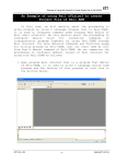
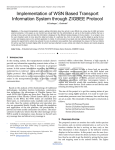
Figure1. Block diagram of LCD display module.
The block diagram of dot matrix liquid crystal display JHD
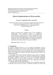
162A module is shown in Fig.1. and its pin configuration 3
is shown in Fig.2 . The Fig. 3 shows the picture of JHD
162A LCD module.
IJSER © 2012
http://www.ijser.org
International Journal of Scientific & Engineering Research Volume 3, Issue 10, October-2012
2
ISSN 2229-5518
Figure 2. Pin configuration of LCD module.
Figure3. LCD module display.
3. Hardware details:
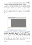
Fig 4.shows the circuit details of interfacing the JHD 162A
with ARM processor. The power supply pins VDD, VSS of
the module are connected between +5V and ground pins,
and wiper terminal of the potentiometer is connected to VL
terminal of the display for adjusting the display contrast.
To read the status of the display the R/W pin is made high.
To write the data in to the display R/W pin is made to be
Low. As we are not reading any data from the display in
the present study, the R/W pin of the display is connected
to the ground. The RS (register select), E(enable) pins of the
display are connected to the P1.28, P1.29 pins of ARM
controller. The data pins D4-D7 of the display are
connected to port P1.24-P1.27 of the microcontroller.
Figure4. Interfacing of LCD Module with ARM processor:
Software details :
Algorithim:
LCD Algorithm:1.
Call Initialization subroutine.
2.
Call print LCD subroutine.
Initialization subroutine:
1.
Set the direction of the pins from 24 to 29 as output
pins for LCD by using register .
2. IODIR1 for port1.
3. Get data to a register.
4. Call command write subroutine for enable 4-bit
mode .
5. Call delay1 subroutine.
6. Call command write subroutine to initialize LCD
in 4-bit mode and two line 5*7dots display.
7. Call delay1 subroutine.
8. Call command write subroutine to clears all
display and returns the cursor to the home
position.
9. Call delay1 subroutine.
10. Call command write subroutine to sets the cursor
move direction and specifies not to shift the
display.
11. Call delay1 subroutine.
IJSER © 2012
http://www.ijser.org
International Journal of Scientific & Engineering Research Volume 3, Issue 10, October-2012
3
ISSN 2229-5518
12. Call command write subroutine to sets ON of all
display, cursor ON, and blink of cursor position
character.
13. Call delay1 subroutine.
14. Call command write subroutine to sets the
CGRAM, data is sent and recived after this setting.
15. Call delay1 subroutine.
Print LCD subroutine:
1.
2.
3.
4.
5.
6.
7.
8.
9.
10.
11.
12.
13.
14.
15.
Some of the registers of LPC 2366 are used in the program
as mentioned in the user manual4.
The program, in detail, written in Embedded C (Keil IDE
vision V4.00)5 as follows.
//--------------Main file-------------//
Take a character and send to data write subroutine.
Call delay subroutine.
Repeate from step 1 to 2 write regsiter untill data
pointer reaches null charecter.
#include <LPC23xx.H>
#include "lcd.h"
int main()
Command write subroutine:
1.
2.
3.
15. Call delay subroutine.
16. Clear enable pin.
Take command data in temperory variable.
Clear data on pins P1.24 to P1.29.
Mask higher nibble with 0xF0 of temperory
variable and left shift with 20.
Send the data in the temporary variable to P1.24 to
P1.29.
Set RS pin 0.
Set enable pin .
Call delay subroutine.
Clear enable pin.
Take command data in temperory variable.
Clear data on pins P1.24 to P1.29.
Mask lower nibble with 0x0F of temperory variable
and left shift with 24.
Send the data in the temporary variable to P1.24 to
P1.29.
Set enable pin.
Call delay subroutine.
Clear enable pin.
{
LCD_INIT();//LCD Initialization
PRINTLCD ("S.K . University");
}
//-------LCD initialization-------//
#include <LPC23xx.H>
#include "lcd.H"
void LCD_CMD_WRT(unsigned char c)//send commands
to LCD
{
long int temp_lcd_value;
temp_lcd_value=c;
Data write subroutine:
1.
2.
3.
4.
5.
6.
7.
8.
9.
10.
11.
12.
13.
14.
TakeLCD data in temperory variable.
Clear data on pins P1.24 to P1.29.
Mask higher nibble with 0xF0 of temperory
variable and left shift with 20.
Send the data in the temporary variable to P1.24 to
P1.29.
Set RS pin to 1.
Set enable pin .
Call delay subroutine.
Clear enable pin.
Take LCD data in temperory variable.
Clear data on pins P1.24 to P1.29.
Mask lower nibble with 0x0F of temperory variable
and left shift with 24.
Send the data in the temporary variable to P1.24 to
P1.29.
Set RS pin to 1.
Set enable pin.
IOCLR1=0x3F000000;
temp_lcd_value=temp_lcd_value&0xF0
temp_lcd_value=temp_lcd_value<<20;
IOSET1=temp_lcd_value;
IOCLR1=0x10000000; //RS clr,cmd
IOSET1=0x20000000;//EN set
LCD_DELAY(delay);
IOCLR1=0x20000000;//EN clr
temp_lcd_value=c;
IOCLR1=0x3F000000;
IJSER © 2012
http://www.ijser.org
International Journal of Scientific & Engineering Research Volume 3, Issue 10, October-2012
4
ISSN 2229-5518
temp_lcd_value=temp_lcd_value & 0x0F;
//=====================//
IOSET1=temp_lcd_value<<24;
VoidLCD_INIT(void)
IOCLR1=0x10000000;//RS clr,cmd
{
//Function to initialise LCD
IOSET1=0x20000000;//EN set
IODIR1=0x3F000000;
LCD_DELAY(delay);
LCD_CMD_WRT(0x20);
IOCLR1=0x20000000;//EN clr
LCD_DELAY1(delay1);
}
LCD_CMD_WRT(0x28);
//=========================//
LCD_DELAY1(delay1);
void LCD_DATA_WRT(unsigned char c) //Function to
send data to LCD
LCD_CMD_WRT(0x01);
LCD_DELAY1(delay1);
{
LCD_CMD_WRT(0x06);
long int temp_lcd_value;
//don't move after display
temp_lcd_value=c;
LCD_DELAY1(delay1);
IOCLR1=0x3F000000;
LCD_CMD_WRT(0x0f);
temp_lcd_value=temp_lcd_value & 0xF0;
LCD_DELAY1(delay1);
temp_lcd_value=temp_lcd_value<<20;
LCD_CMD_WRT(0x80);
IOSET1=temp_lcd_value;
IOSET1=0x10000000; //RS set,data
IOSET1=0x20000000;//EN set
LCD_DELAY(delay);
IOCLR1=0x20000000; //EN CLR
temp_lcd_value=c;
LCD_DELAY1(delay1);
}
//==========================//
void PRINTLCD(unsigned char *ptr)
//Function to print string on LCD
{
IOCLR1=0x3F000000;
while(*ptr!='\0')
temp_lcd_value=temp_lcd_value & 0x0F;
{
IOSET1=temp_lcd_value<<24;
LCD_DATA_WRT(*ptr++);
IOSET1=0x10000000;//RS set
LCD_DELAY(delay);
IOSET1=0x20000000;//EN set
LCD_DELAY(delay);
}
}
IOCLR1=0x20000000;//EN CLR
}
IJSER © 2012
http://www.ijser.org
International Journal of Scientific & Engineering Research Volume 3, Issue 10, October-2012
5
ISSN 2229-5518
#include <LPC23xx.H>
//========================//
void LCD_DELAY(unsigned int i )
#ifndef _LCD_H
//Delay Function
{
#define _LCD_H
#define delay 60000
unsigned int j;
#define delay1 60000
for(j=0 ;j < i;j++);
voidLCD_CMD_WRT(unsigned char);
}
voidLCD_DATA_WRT(unsigned char);
//=========================//
void LCD_INIT(void);
VoidLCD_DELAY1(unsignedinti) //Delay Function
void LCD_DELAY(unsigned int );
{
void LCD_DELAY1(unsigned int );
unsigned int j;
void PRINTLCD(unsigned char *);
for(j=0 ;j < i;j++);
#endif
}
//----Initialisations .h file -----------//
By the execution of the above program the following data
is displayed on Lcd display module.
Data displayed on LCD module is
S.K. University
LPC2366 are described. The necessary software is
developed in Embedded C language. The data written in
the embedded C code is displayed on LCD module in
Line1.
Acknowledgements:
Conclusions:
The hardware and software features of interfacing JHD
162A dot matrix display module with an ARM Processor
The authors are thankful to the University Grants
Commission, New Delhi for providing financial assistance
through
UGC
Major
Research
Project.
References
[1] S.Bhasker Reddy, K. Malakondaiah and S. Raja
Ratnam, Interfacing a Dot Matrix Liquid Crystal
Display Module with Microcontroller, J. Physics
Education, April-June, P. 41-50 (2000).
[2] Douglas V. Hall, Microprocessors and Interfacing
Programming and Hardware, Tata McGraw-Hill,
New Delhi (1993).
IJSER © 2012
http://www.ijser.org
[3] JHD 162A user’s manual.
[4] www.keil.com/dd/docs/datashts/philips/lpc23x
x_um.pdf.
[5] http://www.keil.com/arm/mdk.asp


![E. coli O157 Latex Test [FR]](http://vs1.manualzilla.com/store/data/006407905_1-cbe2f3c21cbb30da624940787b8610da-150x150.png)