1
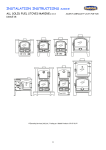
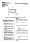
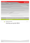
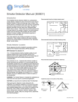
MARINE CORNER SOLID FUEL STOVE
INSTALLER INSTRUCTIONS
ISSUE 06-09-11
http://www.oilstoves.co.uk/
Index
1. Health and Safety. __________________________________________ 4
2. Specifications. ______________________________________________ 4
Dimensions. __________________________________________________
Weight. ____________________________________________________
Output._____________________________________________________
Flue Vacuum. _________________________________________________
4
5
5
5
3. Distance From Combustibles (Appliance.) __________________________ 5
Clearances Above and To The Sides. (Horizontal) ______________________
Clearances Beneath and To The Front. (Hearth Projection and Up stand) _____
Fig 1 Illustration. _____________________________________________
Fig 2 Illustration. _____________________________________________
5
5
6
7
4. Distance From Combustibles (Flue Pipe.)___________________________ 8
4a Ventilation. ________________________________________________ 8
5 Installation Dry Stoves. _______________________________________ 9
Main Steps. _________________________________________________ 9
Securely fastening the appliance. __________________________________ 9
Chimney Systems. _____________________________________________ 9
Fig 4 General Layout of Stove and Flue. ____________________________ 10
Fig 5 General Layout of MK3 Deck Flange Assembly. ____________________ 11
Fireplace Design. ______________________________________________ 11
Fireguards. _________________________________________________ 12
Combustible materials _________________________________________ 12
Deck Flange. ________________________________________________ 12
Firestop Spacer. _____________________________________________ 12
Ceiling Plate. ________________________________________________ 12
Above Deck Extension. ________________________________________ 12
Ventilation – Provision Of. ______________________________________ 12
6. Installation Wet Stoves. _____________________________________ 12
Calorifyers. ________________________________________________
Venting Of Air. ______________________________________________
Pipework. __________________________________________________
Pumped Systems. to BS EN 12828 and BS EN 14336 ___________________
Safety Valve. _______________________________________________
Water Treatment.____________________________________________
Drain Down. ________________________________________________
13
13
14
14
14
15
15
7. Commissioning Dry Stoves. ____________________________________ 15
Pre Firing Checks. ____________________________________________
Post Firing Checks (Dry Stoves.) _________________________________
Instruct The User (Dry Stoves.) _________________________________
Warranty. __________________________________________________
15
15
15
16
8. Commissioning Wet Stoves.____________________________________ 16
Common Problems In Boat Heating Systems. _________________________
Pre Firing Checks (Gravity sytems.) _______________________________
Post Firing Checks (Gravity System.) ______________________________
Warranty __________________________________________________
Pre Firing Checks (Pumped System.) _______________________________
Post Firing Checks (Pumped System.) ______________________________
Instruct The User (Wet Stoves.) _________________________________
16
16
17
17
17
18
18
9. Hot Water System Fault Finding. _______________________________ 18
Fig 6 Gravity Heating Circuit.____________________________________
Fig 7 Pumped Heating Circuit ____________________________________
Glossary Of Terms. ___________________________________________
Bibliograpy _________________________________________________
19
20
20
21
1. HEALTH AND SAFETY.
Take great care when handling materials such as insulation boards, glass fibre ropes,
ceramic wool, fire cements, paints and silicones, they are all irritants and suitable
protective clothing such as disposable gloves dust masks and protective goggles must be
worn.
Wash off thoroughly after handling any of these materials.
Carefully dispose of redundant or surplus materials and always vac up after service or
installation work.
Asbestos There is no asbestos used in the manufacture of this product.
Metal Parts Take care when installing or servicing this product to avoid personal injury.
Alarms Make sure that the vessel is fitted with:1. Optical Smoke Alarm to BS EN14604
2. Carbon Monoxide Alarm to BS EN50291
The appliance must be fitted by a competent person which means, (must have experience
in fitting solid fuel appliances and or HETAS registration.)
DO NOT INSTALL THIS APPLIANCE IN VESSELS POWERED BY PETROL ENGINES OR
ENGINE.
A faulty installation can cause danger to the vessel and its occupants.
2. SPECIFICATIONS.
DIMENSIONS.
Stove Front
Stove Sides
WEIGHT.
Dry Stove
80kg
Wet Stove 90kg
OUTPUT.
Dry Stove 4KW to Space
Wet Stove 3KW to water and 1KW to space.
FLUE VACUUM.
Minimum flue vacuum requirement
.02” W.G. (.068 mbar)
Maximum flue vacuum requirement
.06” W.G. (.204mbar)
3. DISTANCE FROM COMBUSTIBLES (APPLIANCE.)
Unlike rectangular shaped stoves designed to fit into houses, the Corner Bubble Stove is a
marine stove specifically designed for use on Narrow Boats and other craft.
Because of its unique shape it can be fitted tightly into corner locations so as not to cause
an obstruction to either access way, steps or escape routes.
The location must have adequate protection from the effects of radiated and conducted
heat as specified below.
An example of a suitable installation is shown in fig 1 with clearance dimensions shown.
Another example of a suitable installation is shown in fig 2.
To assist with fireplace design, the dimensions of the appliance footprint are shown in fig
1.
The stove has a built in side heat shield and when the stove is positioned in a suitable
location there must be a space of 50mm clearance beyond the outer heat shield, to allow
air to rise up and around it, note that the illustration in fig1 shows a dimension of 70mm
from the stove body, the heat shield is fixed to the stove at a distance of 20mm from the
stove body allowing a further clearance of 50mm.
The space above the heat shield must be left clear to allow heat to rise up and around it;
any obstruction could be dangerous and cause the surrounding materials to overheat.
Do not remove the stove rear heat shield under any circumstances.
CLEARANCES ABOVE
AN D
TO THE SIDES. (HORIZONTAL)
Fireproof materials must be correctly fixed to right angle sides of the location and
extend to a minimum distance of 200mm above the top of the appliance and 150mm past
the sides of the appliance, See fig 1.
CLEARANCES BENEATH
AND
TO THE FRONT. (HEARTH PROJECTION
AND
UP
STAND)
Fireproof materials must be correctly fixed beneath and in front of the appliance,
examples are shown in Figs 1 and 2.
If the fireproof hearth extends 150mm in front of the appliance it must have a 25mm up
stand. See figs 1 and 2.
There should be no combustible fixtures, fittings or furniture other than the floor within
600mm of the front of the appliance, note that the front of the Corner Stove is the flat
front plate, not the angle plates.
FIG 1 ILLUSTRATION. Consists of a fabricated fireplace made from granite, slate, stone or
a suitable fireproof material.
The vertical sides are set at a distance of 70mm from the stove body and are constructed
from 20mm thick fireproof material, next is a 10mm air gap and then a 20mm fireproof
insulation board applied to the lining.
Vertical sides including the ventilated, non combustible capping, extend 20cm above the
appliance.
The hearth plate is constructed from 20mm thick fireproof material, 80mm above the
floor.
In the 60mm space beneath the hearth plate a 20mm fireproof insulation board is fitted
on 10mm fireproof spacers to space it off the floor.
The front up stand is allowed to project 25mm above the hearth plate.
Fig 1.
FIG 2 ILLUSTRATION.
Shows a fireplace fabricated from steel with a ventilated steel front plate allowed to
project 25mm above the hearth plate. This type of fireplace would be fitted up to 25mm
thick fireboards placed on 10mm fireproof spacers extending 20cm above the appliance
and finished off with ventilated non combustible capping.
The appliance would be carefully positioned on the fireplace hearth to give the same 150
mm hearth projection as shown in fig 1.
The hearth plate is constructed from 4mm thick steel plate, 80mm above the floor.
In the 60mm space beneath the hearth plate a 20mm fireproof insulation board is fitted
on 10mm fireproof spacers to space it off the floor.
The front up stand is allowed to project 25mm above the hearth plate.
Fig 2.
4. DISTANCE FROM COMBUSTIBLES (FLUE PIPE.)
Fig 3 shows two illustrations “A” and “B”.
“A” shows the flue pipe fitted with a heat shield and 25mm fireboard lining on 10mm
fireproof spacers. Note that the outer diameter of the flue pipe is spaced at a distance
of 45mm from the 25mm thick fireboard.
“B” shows the shows an alternative where the flue pipe is fitted with a heat shield and a
150mm air gap to a 10mm fireboard spaced off the combustible lining on 10mm non
combustible spacers.
Fig 3
FLUE PIPE A
FLUE PIPE B
4A VENTILATION.
The provision of ventilation for this appliance is 550mm sq for each kilowatt of stove
output.
This equates to 2200mm sq (4”Square) divided between high and low level, directly to
outside air.
If the appliance is fitted into a space which has an extractor fan fitted the additional
ventilation will be required to compensate for the effects of the extractor unit.
If the ventilation is not directly into the space where the appliance is fitted then the
allowance should be doubled.
5 INSTALLATION DRY STOVES.
MAIN STEPS.
Read and thoroughly understand DISTANCES FROM COMBUSTIBLES for flue and
appliance
Select suitable location. Always try to get the stove as low as possible in the boat, this will
allow installation of maximum length flue pipe.
Establish flue position on roof after considering the deck flange sizes.
Design Fireplace. Normally the stove will be fitted in a corner, in a suitable fireplace; this
will predict the angle at which the flue pipe will have to be fitted.
Trial fireplace assembly.
Try Stove in position.
Mark and cut roof plate.
Fit suitable deck flange ass.
Mark, cut and weld flue pipe.
Trial fit fire.
Trial fit everything else.
If it all fits refit it permanently.
SECURELY
FASTENING THE APPLIANCE.
There are two angle brackets provided with the appliance, which can be used for fixing.
It and the flue system must be securely fastened, so as to withstand the normal day-today situations which will be encountered in a narrow boat.
These could be, impact by other vessel, impact into lock gate, the pitching and rolling
effects of inland water sailing.
CHIMNEY SYSTEMS.
The stove must be fitted with our MK3 flue system as illustrated in figs 4 & 5.
The primary flue pipe is fabricated from 4” O.D. tube with a minimum wall thickness of
3mm.
It must be fitted with a flue guard to cover the possibility of anyone touching it and to
comply with the distance from combustibles requirement.
The flue pipe will normally run at a slight angle to allow it to terminate through the ceiling,
in a suitable position.
It is important to make sure that the flue pipe fits concentrically at both the stove end
and as it connects to the twin wall adaptor.
Always fit a rotary swinging cowl to the chimney terminal as illustrated in fig 4.
FIG 4 GENERAL LAYOUT
OF
STOVE
AND
FLUE.
TERMINAL ITEM 9
SECONDARY FLUE
DIA 175
DECK FLANGE ASSEMBLY
150 MINIMUM
100mm PRIMARY FLUE
HEAT SHIELD
FIREPROOF FRAME
FIREPROOF BOARD
WEATHER CAP
FIG 5 GENERAL LAYOUT
OF
MK3 DECK FLANGE ASSEMBLY.
FIREPLACE DESIGN.
Before designing the fireplace, remember that the whole essence of the Corner Bubble is
to make the finished job look like a piece of integrated design.
Figs 1 and 2 show examples of suitable locations.
Make sure that all combustibles are adequately protected from the effects of conducted
and radiated heat.
Protection can be gained by the use of -:
Sheet metal heat shields and non combustible spacers.
Heat resistant boards which have a thermal conductivity of no more than 0.06 W/m-K
FIREGUARDS.
Triangular fireguards and fixing fasteners are available and should always be fitted.
COMBUSTIBLE
MATERIALS
can be-:
Wooden furniture, curtains, wooden panels or frames adjacent to the flue pipe or where it
passes through the deck of the boat, carpet or flooring close to the appliance.
DECK FLANGE.
The deck flange will be fitted as illustrated in figs 4 & 5.
It will be bolted to the roof plate with a seal of silicone rubber applied between the joint.
FIRESTOP SPACER.
The fire stop space will be fitted in between the deck flange and the ceiling plate
concentric to the flue access hole cut in the roof plate of the boat.
It will provide heat protection for any combustible materials located near to the through
roof location.
CEILING PLATE.
The ceiling plate will be fitted inside the boat to finish off the through roof fitting of the
flue pipe.
It will be screwed up to the trimming timber via countersunk wood screws.
Note that B in fig 5 shows how the ceiling plate has been trimmed to allow the flue system
to be positioned a little closer to the roof edge.
ABOVE DECK EXTENSION.
We recommend that a min 28” extension is used when mooring.
In each case we recommend the use of a rotating cowl to minimise the effects of down
draught.
VENTILATION – PROVISION OF.
The provision of ventilation for this appliance is 550mm sq for each kilowatt of stove
output.
This equates to 2200mm sq (4”Square) divided between high and low level, directly to
outside air.
If the appliance is fitted into a space which has an extractor fan fitted the additional
ventilation will be required to compensate for the effects of the extractor unit.
If the ventilation is not directly into the space where the appliance is fitted then the
allowance should be doubled.
For sea going craft (Cat A and B) with closable ventilators, a warning sign (WARNING,
open ventilators before use.) should be fixed near to the appliance.
6. INSTALLATION WET STOVES.
Installation of the wet stove will be the same as the dry except that when dealing with
the location an extra element comes in to the equation and that is connecting the stove up
to the heating circuit.
The stove has a fully integral, powerful boiler, which forms the outer sides of the
triangular shape, down to the top of the ash pit.
This means that above the ash pan area there will only be minimal transfer of heat but
below the boiler, in the ash pit area, there will be heat transfer and suitable heat proof
boards will have to be used to protect from radiated heat in this area.
Before designing the fireplace, take great care about making provision for the boiler
connections and remember that the whole essence of the Corner Bubble is to make the
finished job look like a piece of integrated design.
To facilitate removal of the stove, make sure that there is:Easy access to the boiler unions.
Easy access to the drain down valve.
Water can be connected to the stove via 4 x 1 inch BSP female sockets, welded into the
boiler at the rear top and bottom on either right angle back panel.
Alternative access to either side of the stove, allows the installer to fit the stove in
either port or starboard locations.
Make sure that the vertical sides of the fireplace can easily accommodate the pipe work.
When installing water heating Bubble stoves, the space heating output will be reduced.
The boiler is high water content and suitable for pumped or gravity systems, provided
that they are correctly designed.
If you are not suitably qualified, arrange for a heating engineer to do the design work for
you.
CALORIFYERS.
Indirect calorifiers must be used on gravity or pumped systems.
If you are going to install a gravity system you must make sure that you purchase a special
calorifier with a 28 mm internal diameter coil, don’t be put off by suppliers who say
that they have 28mm connections which are adequate, they are not as effective.
On gravity systems the calorifiers must be located higher than the stove and as close as
possible to it, obviously keeping horizontal runs as short as possible.
VENTING OF AIR.
Gravity or Pumped systems must be open vented with cold feed, ball valve controlled
expansion tanks.
The feed and expansion tank must be as close as possible to the boiler and be fitted at
the highest part of the circuit.
Consult an experienced boat-heating engineer for advice on feed and expansion tanks
which should be manufactured to BS4215 and should be designed to withstand the 500
hour boil test without leaking or collapsing.
To vent the system of air use automatic air vents on all possible air lock locations.
PIPEWORK.
All gravity pipe work must rise on flow and fall on return and be a minimum of 28mm dia.
(35mm dia preferred)
To reduce resistance to flow-:
Use swept bends, do not use elbows.
Use copper pipe work.
Use high water content radiators.
The primary circuit must have a total length of not more than 6 meters otherwise the
recovery time of the calorifyer will be increased beyond an acceptable period of time.
Primary circuit pipe work must not have valves or other devices that can be used to
interfere with the free flow of water.
If the layout of the boat and calorifier restricts the use of gravity pipework to supply the
calorifier, consider the use of a single pump controlled by a cylinder stat to allow hot
water to access the indirect circuit of the calorifier.
An example of a dedicated calorifier pump can be seen in fig 7.
PUMPED SYSTEMS.
Always come off the stove with 28mm copper for a minimum run of 350 mm before
dropping on to 22mm copper pipe, do not use plastic pipework on solid fuel systems.
Great care should be taken with the positioning of the circulating pump or pumps and the
feed and expansion tank to make sure that the water flows where it should and that over
pumping does not occur.
The heating circuit must be piped in 22mm copper with 15mm stabs to radiators.
Fig 7 shows a system employing two pumps, the hot water pump is controlled by cylinder
stat and the central heating pump is controlled by a clip on pipe stat set to turn the
heating pump on at a temperature above 50 deg C.
Where additional radiators are fitted as heat leaks, the pipe work must be kept as short
as possible, rise on feed and fall on return.
SAFETY VALVE.
A 1" safety valve must be fitted as close to the boiler as possible (within 300mm) and the
outlet from it must be directed to a safe location so as not to present any danger should
the valve blow-off and exit steam or boiling water.
Note
Safe location could be through the side of the boat, with a deflector to stop any
horizontal emission.
WATER TREATMENT.
To reduce the build up of lime scale in the primary circuit pipe work the temperature of
the water should not be allowed to exceed 65 Deg C and a suitable water treatment should
be added.
If the boat is to be left unattended the water, in the heating system should also have
suitable antifreeze added or be drained down.
Consult the manufacturer of the antifreeze for advice on the suitability of their product
for use in solid fuel heating systems.
DRAIN DOWN.
A drain down valve should be fitted at the lowest point of the circuit.
CIRCULATING PUMP.
On pumped systems make sure that the circulating pump or pumps are fitted in such a way
as to make it or them easily replaceable, this means lock shielded valves at either side or
easy access.
7. COMMISSIONING DRY STOVES.
PRE FIRING CHECKS.
Check the following, to make sure that they fully comply with the instructions given in
section 2 -:
Fireplace location.
Fixing of the appliance and flue system.
Integrity of the flue system, after first pre heating the chimney system with a blow gun
carry out a smoke test on the appliance and chimney system to make sure that there are
no leaks from either the appliance or the chimney system.
Distances from combustibles.
Ventilation.
Open all the doors, windows and ventilators and read the user instructions on -:
Section 4-2.
Section 6.
Fuels.
Operating procedures.
Light the appliance as per instructions in the user manual.
POST FIRING CHECKS (DRY STOVES.)
When the appliance is going check that there are no fume leaks on the flue pipes and
check that none of the surrounding combustible materials are overheating or showing signs
of overheating.
INSTRUCT THE USER (DRY STOVES.)
Instruct the user on the principles of operation.
WARRANTY.
Fill in the warranty registration details to return to us.
8. COMMISSIONING WET STOVES.
If the stove has been fitted to an existing heating system, make sure that the system is
adequately designed and complies with the details outlined in the section 6.
If the heating circuit does not comply, it must be modified, before attempting to light the
stove.
COMMON PROBLEMS IN BOAT HEATING SYSTEMS.
Inadequate flow of water through the boiler.
Inadequate flow of water through the calorifyer.
Inadequate flow of water through the radiators.
Over pumping.
Air locks.
Lack of safety valves.
Poorly positioned feed and expansion tanks.
Inadequate dia coil fitted in calorifier (for gravity systems always order special
calorifiers with 28 mm dia coils).
Stove fitted out of level allowing an air pocket to build up in the top of the boiler causing
subsequent kettling.
PRE FIRING CHECKS (GRAVITY
SYTEMS.)
If the plumbing system has been designed as a gravity system you should be able to run
the stove without a water-circulating pump.
Carry out all the pre firing checks as per the list in dry stove commissioning before
carrying out the heating system checks.
After these checks have been carried out, check the following-:
The feed and expansion tank is topped up to the specific level.
The system is free from entrapped air.
Check the action of the safety valve and make sure that it is free to blow off at the
required pressure setting of 2.5 bar.
Check that the chimney is free from obstruction and the long extension is fitted.
Check that the inners of the stove are correctly fitted in place.
(Baffle, grate assembly and firebricks.)
Check that there are no closed valves, which are likely to stop the flow of water around
the heating circuit.
After you have checked as above and found everything in order, proceed as follows-:
Light a small fire and build it up slowly.
POST FIRING CHECKS (GRAVITY SYSTEM.)
Keep an eye on the progress of the heat out of the appliance through the system. Heat
will build up in the water and force the water to expand and push itself around the system.
Getting heat into the system is a slow and steady job; let it push through the system
slowly. Once heat is back returning into the appliance the system will gather momentum
and circulation will proceed faster.
At this stage it will then be possible to build the fire up a little as the heating circuit will
be able to dissipate the increasing volume of heat production from the stove.
If the stove is brought up to temperature too quickly there could be some water lost
through the feed and expansion tank.
When you are lighting a stove from cold there will be a build up of condensates on the
boiler surfaces and this can build up to be quite a lot of moisture. As soon as the return
water gets warm this condensation will stop, if the return water does not get hot
condensation may well stream from the appliance.
WARRANTY
Fill in the warranty registration card and return it to us.
PRE FIRING CHECKS (PUMPED SYSTEM.)
Go through the following checking procedure before lighting the stove.
Carry out all the pre firing checks as per the list in dry stove commissioning before
carrying out the heating system checks.
The feed and expansion tank is topped up to the specific level.
The system is free from entrapped air.
Check the action of the safety valve and make sure that it is free to blow off at the
required pressure setting of 2.5 bar.
Check that there are no closed valves, which are likely to stop the flow of water around
the heating circuit.
Turn the water-circulating pump on and make sure that it is running.
When you have turned the pump on make sure that you have enough power in your
batteries or electrical system to keep the pump running all the time that the stove is
under fire.
Check that the chimney is free from obstruction and the long extension is fitted.
Check that the inners of the stove are correctly fitted in place. Baffle. - Grate assembly.
- Firebricks.
After you have checked as above and found everything in order, proceed as follows-:
Light a small fire and build it up slowly.
POST FIRING CHECKS (PUMPED SYSTEM.)
If the plumbing system is working correctly, heat will build up in the water and the
pumped system should quickly move the heat around the system.
Before adding any more fuel to the fire, make sure that the heat in the boiler is being
carried around the pumped system correctly and make sure that the system is not over
pump.
If the stove is brought up to temperature too quickly there could well be some water lost
through the feed and expansion tank or safety valve, replace this water when the system
has settled down.
Make sure that the heating circuit is fitted with a safety valve near to the appliance.
When the fire has settled down, adjust the air control as desired to give the temperature
required.
Note.
If the circulating pump fails, hot water may expand out of the feed and expansion tank
and also out of the safety valve.
Take great care if this happens as the water will be up to boiling temperature and if there
is a big fire in the stove, may soon turn to steam.
Open the front door of the stove and allow it to cool down as quickly as possible.
During the post firing checks it will be possible to check on the effectiveness of the
heating circuit by feeling at the differing pipe temperature. Take great care with this
operation, if the system is not removing heat from the stove, the boiler temperature will
rapidly rise up to boiling point and the pipes will become dangerously hot.
INSTRUCT THE USER (WET STOVES.)
Instruct the user on the procedure to be followed should the pump or pumps stop working.
If the pumps stop working allow the fire to die down as quickly as possible.
Using tongues remove the hot embers safely and extinguish the fire as quickly as possible.
If there is a large fire in the appliance it is possible that water will be emitted through
the safety valve.
9. HOT WATER SYSTEM FAULT FINDING.
If the system does not perform well check the following-:
The design of the circuit.
Pump is not air locked.
The system is not air locked.
Pump has an adequate head.
Pump is running.
The pipe work is adequately sized.
Adequate dia coil fitted in calorifier (for gravity systems always order special calorifiers
with 28 mm dia coils).
The stove is not fitted out of level, allowing an air pocket to build up in the top of the
boiler, causing subsequent kettling.
Adequate flow of water through the boiler.
Adequate flow of water through the calorifyer.
Adequate flow of water through the radiators.
The system is not over pumping.
That the feed and expansion tank is fitted in the correct place.
FIG 6 GRAVITY HEATING CIRCUIT.
GRAVITY SYSTEM
FEED AND
EXPANSION TANK
COLD FEED
35MM COPPER
R1
R2
R3
COLD FEED
DRAIN DOWN VALVE
WHEN USING 35MM PIPE DOWN THE FULL LENGTH OF THE BOAT
ITWILL NOTBE NECESSARY TO FITRADIATORS.
APPLIES TO BOATS 15METRES MIN
FIG 7 PUMPED HEATING CIRCUIT
PUMPED SYSTEM
NRV
22MM COPPER PIPEWORK
GLOSSARY OF TERMS.
Downdraught.
A wind effect creating a situation where air is being
either blown or sucked down the flue pipe.
Chimney vacuum.
generate.
The negative pressure, which the chimney system is able to
Combustible materials.
Any liquids, vapours or materials in close proximity to the
appliance, which can easily ignite with the application of heat or flame.
Thermostat.
A device for controlling temperature.
Multi fuel stove.
A stove which can accommodate all the combustion and other
technical requirements of wood, coal and smokeless fuel burning.
Volatiles.
Combustible entrapped component of hydrocarbon fuel.
Kettling.
reaches boiling point.
Hissing noise like that issued from a kettle just before it
Gravity system. Term used to describe a central heating system through which hot
water will flow, without the use of a circulating pump.
Pumped system.
Term used to describe a central heating system through which
hot water is forced to flow, by the action of an electrically operated circulating pump.
BIBLIOGRAPY
BS 5839-6, Fire detection and fire alarm systems for buildings – Part 6: Code of
practice for the design, installation and maintenance of fire detection and fire
alarm systems in dwellings
BS 8423, Fireguards for fires and heating appliances for domestic use –
Specification
BS EN 14604, Smoke alarm devices
BS EN 50291, Electrical apparatus for the detection of carbon monoxide in
domestic premises – Test methods and performance requirements
BS EN 12828, Heating systems in buildings – Design for water-based heating
systems
BS EN 14336, Heating systems in buildings – Installation and commissioning of
water based heating systems
Other publications
EUROPEAN COMMUNITY Recreational Craft (RC) Directive
94/25/EC amended by Directive 2003/44/EC (europa.eu.int)
© HARWORTH HEATING LTD 07-07-01. ©
This publication must not be copied by any means without written permission from the
authors.
This product is subject to continuous development and improvement and it is consequently
acknowledged, that due to this process, there may be some omissions and errors.
This publication is intended only to assist the reader in the use of this product and
therefore Harworth Heating Ltd. shall not be liable for any loss or damage whatsoever
arising from the use of any information, error or omission found in this guide.
Only approved personnel must carry out maintenance on this product.