1
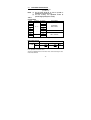
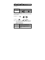
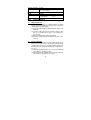
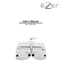
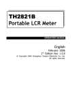
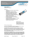
Model :
MIC-4070D
DIGITAL
LCR METER
OPERATION
MANUAL
Inductance Measurement 0.1H to 200H
Capacitance Measurement 0.1pF to 20000F
Resistance Measurement 1mto 20M
Dissipation Factor
Mesaurement
TABLE OF CONTENTS
ONE:
TWO:
INTRODUCTION
1.1
Inspection
1.2
Included Items
1.3
Unit Descriptions
OPTERATION AND MEASUREMENT
2.1
Warning
2.2
Cautions
2.3
875B Zero Adjustment and
Impedance Measurement
2.3.1 Zero Adjustment and Capacitance
Measurement
2.3.2 Zero Adjustment and Inductance
Measurement
2.3.3 Resistance Measurement
2.4
Measurement Parameter
Conversions
THREE: SPECIFICATIONS
FOUR:
3.1
Power Source
3.2
Instrument Specifications
3.3
General Specifications
USEER MAINTENANCE
4.1
Battery Replacement
4.2
In Case of Difficulties
FIVE:
SERVICE INFORMATION
2
ONE:
INTRODUCTION
Congratulations! You have just purchased some of the most
advanced hand-held digital LCR meter available. This meter is
sure to provide years of reliable service.
The MIC4070D is designed to measure the parameters of an
impedance element with high accuracy and speed.
Measurements of inductance, capacitance, resistance
(equivalent series resistance) and dissipation factor are provided
for over a broad band of ranges. In addition, you’ll find that it is
ideal for testing SMD type components. Plus, the instrument
offers advanced features, such as the ability to perform precision
measurements of very low resistances with the 2 ohm and
20ohm ranges, and ideal for high inductances with the 20H and
200H ranges, along with the unique drop-proof construction,
combine to make the unit the most versatile handheld LCR
meter available today.
With proper care and use, these meters can provide years of
reliable operation. Therefore, it is very important to completely
familiarize yourself with the instrument before attempted use.
Please read this manual carefully, paying particular attention to
the safety section.
1.1
Inspection
When you unpack your new Meter from its original packaging,
carefully check each item for damage that may have occurred in
shipment. If anything is damaged or missing, take the entire
instrument, including the box and packing materials, back to the
distributor from whom it was purchased, where they will either
replace the missing or damaged item or the entire instrument.
1.2
Included Items
Meter
Test Leads (1 pair)
1
Battery
SMD type component test probes.
1.3
TL-06. (optional)
Unit Description
Please use the drawings of the MIC4070D, in conjunction with the
following descriptions of the controls and connections to help
familiarize you with the unit:
(1) Liquid Crystal Display
: Indicates the value of capacitance
connected to the test inputs.
(2) LCR/D Mode Switch
: Selects either LCR or Dissipation
Factor measurement mode.
(3) Function/Range Switch : Selects the function and range for
the desired measurement.
(4) Common Terminal Slot : The negative (common) test
connector for all measurements.
(5) Positive Terminal Slot : The positive (high) test connector
for all measurements.
(6) Common Terminal Jack : The negative (low) banana jack for
measurements requiring the use
of test leads.
(7) Positive Terminal Jack : The positive (high) banana jack for
measurements requiring the use
of test leads.
(8) Battery Compartment : Access for the battery.
(9) Tilt Stand
: Used to hold the instrument at an
angle on a level surface, or when
reversed to hang it from a
projection.
(10) Zero Adjust
: Control used to zero the display.
(11) Power Switch
: Turns power to the instrument on
and off.
2
TWO: OPERATION AND MEASUREMENT
2.1
Warning
Electricity can cause severe injuries or even death, sometimes
even with relatively low voltages or currents.
Therefore it is vitally important that any electronic instruments such
as these meters be totally understood before use.
Please do not use this instrument, or any other piece of electrical
or electronic test equipment, without first thoroughly familiarizing
yourself with its correct operation and use.
2.2
Cautions
(1) To obtain accurate impedance values, perform zero
adjustment before measurements.
(2) Attempted measurement of charged capacitors will overload
the instrument.
(3) If a dead or partially discharged battery is left in the instrument
for an extended period, damage to the unit could result from
battery leakage. Therefore it is important to replace a
discharged battery promptly. Please dispose of the used
battery in a proper manner. Additionally, if the instrument will
not be used for an extended period, always remove the
battery from the unit and store it separately.
(4) Do not use solvents or aromatic hydrocarbons to clean the
instrument, or the plastic case may be damaged. If cleaning is
necessary, use only a mild solution of warm water and soap.
(5) Capacitors are manufactured to operate under certain
conditions. Since the meter may test a capacitor under
different conditions than of the manufacturer, the values
3
might not be identical. This is not due to meter error, just
the method of test. Therefore, if this is the case, check
the capacitor’s dissipation factor (0.1) and whether the
test was conducted in series or parallel mode (ref.
Section 3.6). Use the equations to convert between the
modes. At this point, one should obtain a value to that
stated on the capacitor.
(6) To ascertain if the meter is accurate, please use a
standard capacitor that states test conditions.
2.3
MIC4070D Zero Adjustments and Impedance Measurements
IMPORTANT INFORMATION:
1. As an added feature, the MIC4070D has +/- offsets. The
+/-offsets allow for measurements when the LCD is not at zero.
The +/- offsets are applicable to components that are
measured in the following modes: capacitor parallel (Cp),
inductor series (Ls) and resistance series (Rs). The +/- offsets
are not applicable for components that are tested Cs, Lp or Rp.
To use this feature, just simply add/subtract the value from the
measured value of a component.
2. For impedance measurements there are two different test
modes: parallel and series. These distinct test modes obtain
different results. Refer to section 2.4 for conversions.
2.3.1
Zero Adjustment and Capacitance Measurement
(1) Set the power switch to the “on” position.
(2) Set the mode switch to the “LCR” position.
(3) Set the Function/Range switch to the appropriate capacitance
range for the capacitor under test. If the capacitance value is
unknown, select the 200pF range.
NOTE: If test leads will be used in the measurement, have them
plugged in the banana jacks, but not connected.
4
200pF, 2nF, 20nF, 200nF & 2µF Range (Cp):
Zero Adjustment (Cp Mode)
(4) Set the Capacitance meter to the selected Capacitance
range.
(5) Using a small, flat-blade screwdriver, slowly turn the “0 Adj”
control to calibrate the display for a zero reading. Now the
meter is calibrated for these four ranges.
(6) Set the meter to proper capacitance range and go to step
seven to measure capacitance.
20µF, 200µF, 2mF & 20mF (Cs): Range
Zero Adjustment (Cs Mode)
(4) Set the capacitance meter to the 2µF Capacitance range.
(5) Using a small, flat-blade screwdriver, slowly turn the “0 Adj”
control to calibrate the display for a zero reading. Now the
meter is calibrated for these four ranges.
(6) Set the meter to proper capacitance range and go to step
seven to measure capacitance.
Capacitance & Dissipation Factor Measurements
(7) Discharge the capacitor to be measured.
(8) Insert the capacitor leads into the component test sockets at
the front of the meter. If the capacitor leads are too short, use
the alligator clip leads provided with the instrument to connect
to the capacitor. Be sure to observe the proper polarity if the
capacitor is a polarized type.
(9) Read the capacitance value in the display. If “1---“(a one with
the following 3 digits blanked) is shown (which indicates an
over-range reading), move the range switch to the next higher
capacitance. If necessary, perform zero adjustment before
measurement.
(10) To measure the “Dissipation Factor” of the capacitor, set the
5
mode switch to the “D” position, and read the dissipation
factor value in the display.
(11) ESR Fur capacitors
“Equivalent Series Resistance” is typically much larger than
the actual “ohmic” series resistance of the wire leads and foils
that are physically in series with the heart of a capacitor,
because ESR includes also the effect of dielectric loss. SR is
related to D by the formula ESR=Rs=D/wCs (where w
represents “omega” =2 pi times frequency). In 20mf range,
the dissipation factor can be obtained by the formulary D=
WCsRs where Cs in the measured value and Rs is
measured by 2 range.
NOTE: To avoid possible damage to the instrument, discharge all
capacitors before attempting to measure the value or
dissipation factor.
2.3.2
Zero Adjustment and Inductance Measurements
200µH, 2mH, 20mH, 200mH range (Ls):
Zero Adjustment & Measurements
(1) Set the power switch to the “on” position.
(2) Set the mode switch to the “LCR” position.
(3) Set the Function/Range switch to the appropriate range for the
inductor under test. If the inductance value is unknown, select
the 200µH range.
NOTE: Each range must have zero adjustment performed.
(4) Using a short piece of wire, such as a paper clip, temporarily
connect the positive and negative measurement terminals
together. Alternatively, if the clip leads will be used for the
measurement plug them into the banana jacks and connect
the clips together.
(5) Use a small, flat-blade screwdriver and slowly turn the “0 Adj”
6
control to calibrate the display for a zero reading. Remove the
calibration short.
(6) Insert the inductor leads into the component test sockets at the
front of the meter. If the leads are too short, use the alligator
clip leads provided with the instrument to connect to the
inductor.
(7) Read the inductance value in the display. If “1---“ (a one with
the following 3 digits blanked) is shown, move the range
switch to the next higher range until the over range indication is
gone from the display. Repeat steps 4-7.
2H, 20H, 200H, range (Lp): Zero Adjustment & Measurements
(1) Set the power switch to “on” position.
(2) Set the mode switch to the “LCR” position.
NOTE: These three ranges (Lp mode) must be zero calibrated at
200mH range.
(3) Set the Function/Range switch to the 200mH range.
(4) Using a short piece of wire, such as a paper clip, temporarily
connect the positive and negative measurement terminals
together. Alternatively, if the clip leads will be used for the
measurement, plug them into the banana jacks and connect
the clip together.
(5) Use a small, flat-blade screwdriver and slowly turn the “0 Adj”
control to calibrate the display for a zero reading. Remove the
calibration short.
(6) Insert the inductor leads into the component test sockets at the
front of the meter. If the leads are too short, use the alligator
clip leads provided with the instrument to connect to the
inductor.
(7) Read the inductance value in the display. If “1---“ (a one with
the following 3 digits blanked) is shown, move the range
7
switch to the next higher range until the over range indication is
gone from the display and a value is obtained.
(8) To measure the “Dissipation Factor” of the inductor, set the
mode switch to the “D” position, and read the dissipation factor
value in the display.
2.3.3 Resistance Measurements
NOTE: A. The 2, 20, 200, 2K, 20K, 200K, ohm ranges of resistance
needs to be zero adjusted separately.
B. To zero adjust the 2M ohm and 20M ohm ranges, set
the range switch to the 200K ohm range and zero
adjust.
(1) Turn unit on.
(2) Set the mode switch to the “LCR” position.
(3) Set the Function/Range switch to the appropriate resistance
range. If the value of resistance is unknown, select the 2 ohm
range.
(4) Using a short piece of wire, such as a paper clip, temporarily
connect the positive and negative measurement terminals
together. Alternatively, if the clip leads will be used for the
measurement, plug them into the banana jacks and connect
the clips together.
(5) Use a small, flat-blade screwdriver and slowly turn the “O Adj”
control to calibrate the display for a zero reading. Remove the
calibration short.
(7) Insert the resistor leads into the component test sockets at the
front of the meter. If the leads are too short, use the alligator
clip leads provided with the instrument to connect to resistor.
2.4
Measurement Parameter Conversions
The parameter value for a component measured in a parallel
8
equivalent circuit and that value measured in a series equivalent
circuit may be different from each other. This means that the
parallel-measured capacitance (inductance) of any given capacitor
(inductor) will not be equal to the series-measured capacitance
(inductance) unless the dissipation factor of the capacitor (inductor)
equals zero. The equations in the table below show the
relationship between the parallel- and the series- measured
parameters of any given components:
Dissipation Factor Equations
(See table 1)
E.G.1: With a measurement frequency of 1K Hz, a parallel mode
capacitance of 1000pF with a dissipation factor of 0.5 is equal to a
series mode capacitance of 1250pF.
Cs( 1 D × D ) × Cp
Cs( 1 0.5 × 0.5 ) × 1000pF
Cs1250pF
E.G.2: With a measurement frequency of 1K Hz, a series inductance of
1000uH with a dissipation factor of 0.5 has a series resistance of
3.14 ohms.
Rs2 × 3.14 × f × Ls × D
Rs2 × 3.14 × 1K × 1m × 0.5
Rs3.14
However, at any given measurement frequency, the dissipation
factor of a component is the same for both parallel equivalent and
series equivalent circuits.
Additionally, the reciprocal of the dissipation factor (1/D) is
equivalent to the quality factor (Q).
9
THREE:
3.1
SPECIFICATIONS
Power Source
Battery Type: 006P 9V battery.
Power Consumption’s: 155mW
10
Cp mode
Section 2.4 Measurement Parameter Conversions
Table 1. Dissipation Factor Equations
Dissipation Factor
Conversion to other modes
1
1
D2
D=
(= )
Rp
Cs = (1 + D 2 )Cp, Rs =
2πfCpRp Q
1 + D2
Circuit Mode
Cs mode
D = 2πfCsRs (=
Lp mode
1
)
Q
Cp =
1
1+ D
2
1+ D2
Cs , Rp =
D2
D2
D=
2πfLp
1
(= )
Rp
Q
Ls =
D=
Rs
1
(= )
2πfLs
Q
Lp = (1 + D 2 ) Ls , Rp =
1
1+ D
2
Lp , Rs =
1+ D2
Rs
Rp
Ls mode
11
1+ D2
D2
Rs
3.2
INSTRUMENT SPECIFICATIONS
Electrical Specifications
(See tables 2)
NOTE: (1) The test leads should be as short as possible to
minimize the measurement error.
(2) For best accuracy, zero adjustment should be
performed appropriately before testing.
Table 2.
CAPACITANCE
Test Condition
Range
*Accuracy Resolution
200pf
0.1pf
2nf
1pf
Parallel Mode
20nf
10pf
1%2
1KHz, 0.5Vrms
200nf
100pf
2µf
1000pf
20µf
0.01µf
Series Mode 120Hz, 1mArms
200µf
0.1µf
Series Mode
1µf
2mf
120Hz, 10mArms
2%10
20mf
10µf
*Accuracy is ± ( % of readingnumber of digits ) When D0.1
DISIPATION FACTOR
Range
200pf
0 ~ 1.999
N.S.
2nfCx2µf
Accuracy
2µfCx2mf
20mf
N.S.
2000
2000
1% + 10 +
2% + 20 +
Cx
Cx
Accuracy is ± ( % of readingnumber of digits ).
Cx is capacitance readout in counts.
Accuracy is applied when C is from 20 to 100% of full scale range in series
mode measurements.
13
Parallel Mode Dc =
1
2πfCpRp
Series Mode Dc = 2π fCsRs
RESISTANCE
Range
Accuracy Resolution
Test Condition
2Ω
1%5
1mΩ
10mArms
Series
20Ω
10mΩ
10mArms
Mode
200Ω
100mΩ
1mArms
1KHz
1%2
2KΩ
1Ω
0.1mArms
20KΩ
10Ω
10µArms
200KΩ
100Ω
1µArms
2MΩ
Parallel Mode
1KΩ
2%2
1KHz, 0.5Vrms
20MΩ
10KΩ
Accuracy is ± ( % of readingnumber of digits ) and is applied from 10 to
100% of full scale range in parallel mode measurements.
In series mode measurements, the compliance voltage (voltage drop on the
device under test) should be less than 0.2 Vrms.
INDUCTANCE
Range
Accuracy
200µH
2%2
2mH
1%2
20mH
200mH
2H
2%2
20H
Resolution
0.1µH
1µH
10µH
100µH
1mH
10mH
14
Test Condition
10mArms, 1KHz
Series
10mArms, 1KHz
Mode
1mArms, 1KHz
0.1mArms,1KHz
Parallel Mode
200H
3%2
100mH
120Hz, 0.5Vrms
Accuracy is ± ( % of readingnumber of digits ) When D0.1.
The accuracy is applied from 10 to 100% of full scale range in parallel mode
measurements.
DISSIPATION FACTOR
Range
Accuracy
Lx200mH
200mHLx200H
0 ~ 1.999
2000
2000
1% + 10 +
2% + 20 +
Lx
Lx
Accuracy is ± ( % of readingnumber of digits ).
Lx is inductance readout in counts.
Accuracy is applied when L is from 20 to 100% of full scale range in parallel
mode measurements.
Parallel Mode DL = 2πf
Lp
Rp
Series Mode DL =
Rs
2πfLs
NOTE : ALL THE ACCURACY IS GUARANTEED AT TEMPERATURE
OF 15 TO 28, RELATIVE HUMIDITY TO 80% AND HALF
YEAR CALIBRATION CYCLE.
3.3
GENERIAL SPECIFICATIONS
Power
Single 9V 006P Battery
0.5digital height, 3 1/2 digits liquid crystal
Display
display with “LOBAT” and decimal annunciates
Display will show “LOBAT” in the last 5% of
Low Battery Warning
Battery life
15
Current Consumption 17.3mA
0 ~ 40, Operating
Temperature
-20 ~ 70, Storage
Dimensions
177×88×40mm
Weight
400 gram
Test Clips (red & black)
1 pair
Standard Accessories
Operation Manual
1 piece
Optional Accessories Measurement clip TL-06 for SMD type component
FOUR:
USER MAINTENANCE
4.1
Battery Replacement
When the instrument displays the “LO BAT” indication, the battery
must be replaced to maintain proper operation. Please perform the
following steps to change the battery:
(1) Remove the battery hatch by sliding it towards the bottom of the
instrument.
(2) Unsnap the battery clip from the old battery. Snap the clip in
place on a new battery. Please dispose of used batteries in a
proper manner.
(3) Place the new battery in the battery compartment.
(4) Replace the battery hatch by reversing the procedure used to
remove it.
4.2
In Case of Difficulties
These meters are designed to be accurate, reliable, and easy-to-use.
However, it is possible that you may experience difficulties during
operation. If there appears to be any kind of problem during use of
the instrument, please perform the following steps to help determine
the source:
(1) Reread the operating instructions. It is very easy to inadvertently
make mistakes in operating procedure.
(2) Inspect and check the continuity of the test leads. The instrument
will not function properly with broken test leads.
16
(3) Remove and test the battery. The instrument will not function
properly with a discharged battery.
If the proceeding three steps fail to resolve the problem, please refer
to the “Service Information” section or contact your nearest
distributor.
NOTE: ATTEMPTED REPAIR, MODIFICATIONS, OR TAMPERING BY
UNAUTHORIZED PERSONNELWILL VOID THE WARRANTTY.
EC Declaration of Conformity
-Electro Magnetic Compatibility-Low Voltage DirectiveThe equipment herewith complies with the requirementsents of the EMC Directive 89/
336/EEC and the LVD 73/23/EEC and 93/68/EEC.
Declares that this equipment conforms to the following product specifications:
EMC:
CISPR22
: 1993, and EN 55022, 1994, Class B
IEC 1000-4-2 : 1995,and prEN 50082-1, 1994-4KV CD, 8KC AD
IEC 1000-4-3 : 1995, and prEN 50082-1, 1994-3V/m
IEC 1000-4-4 : 1995, and IEC 801-4, 1988-1KV,5/50ns, 5KHz AC power port
IEC 1000-4-5 : 1995, and prEN 50082-1, 1994, Surge-1KV, AC power port
EN 60555-2 : 1987, Harmonics, Class A
EN 60555-3 : 1987, Voltage Fluctuations
Test Report Number : 500-8410-10 (EMI)
500-8409-27 (EMS )
LVD:
EN 61010-1/EN 61010-2-031
Test Report Number : 97407-1 ( LVD )
Manufacture’s Name : MOTECH INDUSTRIES INC.
Manufacture’s Address : 6F, NO. 59 Tsao – Dih Woei,
Wan Shun Liao, Shen Keng Hsiang.
Taipei; Hsien 222, Taiwan, R.O.C.
17 for use with a AC to DC adaptor, only
Modification : The MIC-4070D is not designed
Just enough use with 9V 006P Battery. (please cancel item 3.1 on
Page9 of operation manual).
Current Consumption : 10mA average (see manual page14). 17.3mA maxima
Type of Equipment : Hand-held LCR Meter
18