1
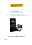
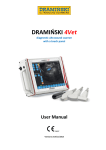
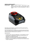
ULTRASOUND SCANNER WITH MECHANICAL SECTOR PROBES USER MANUAL www.draminski.com TABLE OF CONTENTS 1 2 3 4 5 INTRODUCTION .................................................................................................... 3 PACKING LIST ....................................................................................................... 4 MAIN COMPONENTS ............................................................................................ 4 HARDWARE CONNECTIONS ............................................................................... 5 SOFTWARE ............................................................................................................ 7 5.1 Installation ...................................................................................................... 7 5.2 Elements displayed on screen ..................................................................... 11 5.3 Menu structure ............................................................................................. 12 5.4 Probe setup .................................................................................................. 14 5.5 Cineloop ....................................................................................................... 14 5.6 Imaging modes ............................................................................................ 14 5.7 Saving images ............................................................................................. 16 6 MEASUREMENTS ................................................................................................ 18 6.1 Measurement modes ................................................................................... 18 6.2 Coarse dimensioning.................................................................................... 18 7 TECHNICAL SPECIFICATIONS ........................................................................... 19 8 EXAMINATION OF ANIMALS ............................................................................... 20 8.1 Getting the scanner ready ............................................................................ 20 8.2 Sample images taken in bitches and cats .................................................... 20 9 MAINTENANCE .................................................................................................... 22 10 TROUBLESHOOTING ....................................................................................... 22 11 SHORTCUT KEYS ............................................................................................. 23 1 1 Introduction B-Mode ultrasonography is a real-time imaging technique that may be applied to graphically present two-dimensional cross-sections of body tissues/organs. Very often it is the diagnostic method of choice that has won a permanent place in veterinary practice. The brighter points of the images displayed on the ultrasound scanner monitor represent body points that reflect more ultrasound waves than other points. Body tissues reflect a large fraction of the waves and are displayed as collections of light points. On the other hand, body liquids that transmit the waves without echoing them are displayed as collections of dark points. The quality of the images produced by ultrasound scanners depends on the frequency of waves emitted by the scanner probe (transducer, head): the higher the frequency, the higher the image resolution. However, body penetration depth decreases for higher frequencies, since acoustic wave attenuation/scattering coefficients are almost proportional to the frequency of the wave. The knowledge and experience of the individual operating the scanner has a large influence on the effect of the correct interpretation of the images produced by ultrasound scanners, as does performing examinations in line with all ultrasound diagnostics standards and making use of all the capabilities of the scanner. The DRAMIŃSKI SONTRACE VET system offered by the DRAMIŃSKI company is a device dedicated to performing quick, convenient and reliable diagnostic examinations in veterinary practice. This mobile device may be carried inside a laptop bag or used as a stationary ultrasound scanner. The scanner is powered from a USB port of a laptop. The DRAMIŃSKI SONTRACE VET system is a costeffective solution since it may be based on an already owned/used laptop/PC computer. The DRAMIŃSKI SONTRACE VET system may be used in a veterinary office as a stationary ultrasound scanner. However, at any moment all its components may be packed into a laptop bag and used in the field as a mobile scanner. 2 2 Packing list Item Description Qty 1 SONTRACE scanner with USB port and 12-pin probe port 1 2 Abdominal (5.0 MHz) and/or (7.5 MHz) mechanical sector probe 1 3 USB-USB cable 1 4 CD with the DRAMIŃSKI SONTRACE VET system software (to be installed on 1 an owned/used computer) 5 Transport packaging with foam lining 1 6 User manual and warranty certificate 1 3 Main components The DRAMIŃSKI SONTRACE VET system is composed of the three following main components: 1. Housing, with probe electronics, circuits responsible for communication with the co-operating computer and suitable sockets 2. Ultrasound probe 3. DRAMIŃSKI SONTRACE VET system software. 3.1 Housing Made of high quality aluminum (high impact strength). Two sockets are mounted on the two side walls of the housing and a USB socket used for the communication of the SONTRACE VET system with the laptop or PC: 1) On the side walls of the housing, two sockets can be found: 12-pin socket used to connect the scanner ultrasound transducer (probe) 2) socket used to hook the system up to a PC computer/laptop USB port (via an USB-USB cable). 3.2 Mechanical, abdominal sector probe 5.0 or 7.5 MHz The DRAMIŃSKI SONTRACE VET system works with mechanical sector probes dedicated to the abdominal examinations of small and big animals. Due to the complicated mechanism (with a piezoelectric transducer immersed in oil), the probes must be protected against falling or against other mechanical impacts. The probe cap covers a piezoelectric ultrasound-generating element immersed in a special oil. The cap must be protected against mechanical damage and scratches. 3 Mechanical sector probe, frequency 5.0 MHz. Scanning angle 90°, penetration depth up to 20 cm. May be used to examine small as well as big animals. 4 Hardware connections The device is supplied with electric power from the USB port of the co-operating computer. The system draws about 500 mA current. Prior to connecting the system to a USB port of a computer, check if the selected port is rated for such load. Connect the probe cable to the SONTRACE VET system housing socket. Connect one end of the USB cable to the housing rectangular socket and plug the other end into a computer USB port. The scanner hardware is ready for operation. 4 5 Software Before the DRAMIŃSKI SONTRACE VET system may be used, the software, delivered with the equipment, must be installed. The software is responsible for displaying the acquired images and the system control panel on the co-operating computer screen. 5.1 Installation The Setup.exe installer is delivered on a CD. Follow the instructions below to install DRAMIŃSKI SONTRACE VET system software: a. Insert the CD to your CD/DVD reader. b. Run the setup.exe program. c. Wizard splash screen displays a welcome message, recommends that all applications that might be running in your computer be shut down and prompts the Next button to be pressed. Shut the programs down and click Next. 5 d. The wizard proposes a default folder where the software is to be installed. Press Browse and select another target folder or simply press Next to stay at the folder proposed by the installer. e. The wizard proposes default shortcut folder in the Start menu. Press Browse and select another folder or simply press Next to stay at the folder proposed by the installer f. The wizard displays the selected installation parameters. If everything is OK, click Install. 6 g. At some moment the installation procedure will display the following window with a prompt to hook up the device to an USB port of the computer and to press any key. Device USB device driver will be installed at this stage. 7 h. The wizard displays the last screen. Click Finish. The DARMIŃSKI SONTRACE VET shortcut icon will appear on the computer desktop. Click the icon to run the system. At the very first run of the SONTRACE VET system the computer operating system may display a prompt to install drivers of the connected USB device. Follow the onscreen instructions. SONTRACE VET system drivers are stored in the driver subfolder of the main program folder e.g. c:\program files\draminski\sontraceVet\ driver 8 5.2 Elements displayed on screen Image brightness (gamma) amplification in further field (gain 2) amplification in closer field (gain 1) Freeze the image / resume scanning Program menu Vertical and horizontal ruler (1 cm markers) Image data Image Scanner imaging modes Cineloop controls Transducer frequency Ultrasound beam penetration depth Image zoom 9 INTENSITY SLIDER – Adjust brightness of the entire image. GAIN SLIDER – Adjust the brightness of features echoed in the deep field (Gain2) and/or in the closer field (Gain1) of the image STOP/START BUTTON – stop imaging and freeze the on-screen image/ re-start scanning. Once the image is frozen, Cineloop-related buttons automatically become active (see the Cineloop section below) PROGRAM MENU – Systematic description of all menu options may be found below in the "Menu structure” section. RULERS or GRID are elements that help to roughly (visually) evaluate the size of image features. Ruler markers and lines of the grid are evenly distributed every 1 cm. These elements may be changed or turned on/off with the management menu IMAGE DATA displayed in the image upper left corner may include: User name Current date/time Ultrasound beam penetration depth probe frequency Zoom Distance (if measured) Area (if measured) Volume (if measured) Fetus age (if calculated on the basis of some performed measurements) FREQUENCY – center of the frequency band (in MHz) emitted by the probe ultrasound transducer to scan tissues. The higher frequency, the larger the beam attenuation, hence images acquired at higher frequencies are typically darker than those acquired at lower frequencies. DEPTH – beam penetration depth in cm ZOOM – image zoom (according to user preferences or the screen of the cooperating laptop). Remember that larger images may require more powerful computers in order to display images. 5.3 Menu structure 5.3.1 The FILE submenu Options related to saving images to disk files and retrieving images from the disk include: Save image – save the displayed image together with all its accompanying data as a file stored in the default image folder (currently Moje obrazy\USG). Save image as – save the displayed image together with all its accompanying data as a file stored in a folder selected by the user in the displayed dialog window. (Any file may be selected for saving the image in.) Retrieve image – load a specified image and all its accompanying data from its disk file to the program (e.g. to measure dimensions of some image features). 10 Open image folder – display Windows Explorer window with contents of the default image folder (currently Moje obrazy\Sontrace). Exit – shut down the application. 5.3.2 The CINELOOP sub-menu A few hundred of the most recently acquired image frames are stored in the computer memory in sequence, i.e. one after the other Options related to Cineloop include: Save Cineloop – save a Cineloop sequence to a disk file. Retrieve Cineloop – load a saved Cineloop sequence to the program from a specified disk file. Reset Cineloop – reset the Cineloop memory (the material in the computer memory is deleted and a new Cineloop sequence may be started). Jog backwards – display previous frame. Jog forwards – display next frame. Replay backwards – play the Cineloop sequence backwards. Replay forwards – play the Cineloop sequence forwards. 5.3.3 The SETUP sub-menu Operator ID – enter the operator's name (that data is displayed in the upper left corner of the image and is stored together with the image to disk file). Probe setup – set the used ultrasound probe up. Grid/rulers – turn the on-screen grid/rulers ON/OFF. Application folders – set the default disk folder for images and the default disk folder for Cineloop sequences up. Language – select user interface language. All communication in this program will now appear in the chosen language. 5.3.4 The MEASUREMENTS sub-menu Length – turning on this mode means that the program will work in the linear measurement mode (depths and distances). Mark the beginning and the end of the distance to-be-measured. Area – area measurement mode. Drag around the feature to-be-measured. Volume – volume measurement mode. In this mode three measurements are required. Upon carrying out the third measurement, the volume is calculated. Fetus age – select an algorithm according to which the measured distance is to be converted to fetus age. 5.3.5 The HELP sub-menu About the program – display a window with information on the program. WWW – Internet address of the program Webpage. 11 5.4 Probe setup In principle the probe set up procedure must be carried out only when a new, replaced or serviced probe is hooked up for the first time to the scanner. The objective of the procedure is to stabilize images displayed on screen (in the case of abdominal probes). The scanner remembers the settings of individual probes and no later setups are necessary. To set up a probe: Select the Probe setup option in the Settings menu. A window with a horizontal adjustment bar is displayed on screen. Using the Navi buttons or your mouse move/drag bar slider to the left/right to optimize image stability. Press OK to confirm. 5.5 Cineloop 256 most recently acquired image frames are stored in the computer memory. At any moment the operator may freeze the new image and replay the stored frames e.g. to precisely study their sequence step-by-step. Such sequences (and the function to replay them) are called Cineloop. The sequences may be browsed frame by frame in the forward direction, in the backwards direction, or replayed as a video sequence. Every sequence may be stored within a disk file so that it might be replayed at any time in the future. Each frame in a Cineloop sequence may be treated as any realtime acquired image, e.g. every of its objects/features may be measured. 5.6 Imaging modes The program supports the three following imaging modes: the B mode the B+B mode the B+M mode 5.6.1 single “B” image two “B” images side by side “B” image side by side with “M” image Imaging mode selection Use the mode. icons in the operator panel to select the imaging 12 5.6.2 The B mode A single “B” image is displayed. 5.6.3 The B+B mode Two “B“ images are displayed side-by-side: the left one is produced in real-time by the probe, the right one is the image stored at the moment the B+B button was pressed. 13 5.6.4 The B+M mode Two images produced in real-time by the probe are displayed side-by-side: the left one is the “B” image, the right one is the “M” image. 5.7 Saving images Use the File> Save menu option to save the acquired image to a disk file stored in the default folder. A filename will be automatically created by the program. Use the File>Save As menu option to save the acquired image to a disk file stored in an arbitrary folder that may be selected in the displayed dialog window. This option enables the user to enter a non-standard name for the file. 5.7.1 Patient data Once the image is saved the program displays a prompt to enter additional data of the examined patient. The data will be displayed in the upper left corner of the image area on the screen and optionally may be saved in disk file together with the image: click the Add button in the prompt window to embed the data into the image or otherwise click the Cancel button. 14 The Name, Surname, Age, Address text boxes accept only one line of text per box. Multi-line data may be entered into the Description text area. 15 6 Measurements 6.1 Measurement modes Use the respective Measurement menu option to turn on one of the three available measurement modes. 6.1.1 Distance The software calculates the distance between two indicated points and additionally shows the depth of the first point. 1. Move the mouse cursor to the first point. 2. Press the left mouse button and hold it down. 3. Drag the cursor to the other end of the measured line. 4. Release the left mouse button. 5. End of the measurement, the software displays the result on the image. 6.1.2 Area The software calculates the area of the object indicated by its perimeter. 1. Move the mouse cursor to any point of the object perimeter. 2. Press the left mouse button and hold it down. 3. Drag the cursor around the perimeter. The program traces the path with dots. 4. When the path is closed, release the left mouse button. 5. End of the measurement, the software displays the result on the image. 6.1.3 Volume The volume of an object may be measured if two perpendicular projections of the object (e.g. a top view and a side view) are available. Each volume measurement consists of three successive distance measurements (object length, width, and height). 1. Orient the probe so that the object length is visible in the acquired image. 2. Measure the length. 3. Orient the probe so that object width is visible. 4. Measure the width. 5. Orient the probe so that object height is visible. 6. Measure the height. 7. End of the measurement, the software displays the result on the image. 6.2 Coarse dimensioning Use the on-screen rulers or grid to coarsely evaluate the dimensions of objects visible in the acquired images. Use the respective Setup menu option to turn the rulers/grid ON/OFF. 16 7 Technical specifications Imaging mode Frequency and type of probes B Mode real-time imaging CineLoop sequences, max. 256 frames per sequence Mechanical, sector, abdominal 5.0 MHz Mechanical, sector, abdominal 7.5 MHz Penetration depth (depending on the probe type) 15 cm, 12 cm, 10 cm, 7 cm Penetration angle 90° for abdominal probes Function controls Computer keyboard (keyboard shortcuts) Mouse cursor (laptop touchpad or a mouse) Image memory capacity Limited by computer HDD disk capacity Power supply Computer USB port, 5 V Dimensions (L x W x H) 11.5 x 8.5 x 3.5 cm Weight 250 g without probe Operating temperature range +5…40°C Storage temperature range 0…+45°C 17 8 Examination of animals 8.1 Getting the scanner ready Prior to commencing the operation get all necessary accessories ready. 1 Run the DRAMIŃSKI SONTRACE System software on the computer. 2 A dedicated gel (recommended for ultrasonographical applications) is indispensable in order to operate the scanner. It is best to make sure that the gel is certified for ultrasound applications. Other gels may in practice turn out to be inconvenient and of low efficiency, or may also bring about undesirable side effects. Good quality gel is definitely indispensable if ultrasound signals are to be transmitted efficiently to produce correct and clearly legible images. In the case of thick-furred animals diluted alcohol may also be used. Before commencing work make sure the amount of gel at your disposal is sufficient to perform all the planned examinations. 3 Factors influencing the image quality include the correct preparation of the animal for examination, the place where the probe touches the body, penetration plane (i.e. the angle at which the probe touches the body), amount of gel used and the scanner operator's skills. 4 During the examination use the available operator panel controls to select the optimum parameters of the scanner on a case by case basis. In particular optimize the gain and the penetration depth. By default the system applies the most recently used settings. 8.2 Sample images taken in bitches and cats 25th day of pregnancy 27th day of pregnancy 18 heart (both cardiac ventricles) bladder liver with blood vessels liver kidney york’s heart – liquid in pericardium 19 9 Maintenance During operation the scanner usually gets dirty. Immediately after finishing the work it should be cleaned with a damp (but not wet) cloth soaked with a mild detergent solution. Protect scanner sockets for the time the scanner is cleaned. A probe may be either washed in running water, immersed in a mild detergent solution, or immersed in a suitably diluted disinfection solution (most often 1% solutions like those use to disinfect medical equipment, e.g. Incidin manufactured by ECOLAB or Cidex manufactured by Johnson&Johnson). Protect the 12-pin plug at the end of the probe cable from getting wet. Do not use any concentrated, aggressive, or scrubbing agents. During cleaning, protect all plugs/sockets against getting wet. 10 Troubleshooting Problem Recommended action Unstable image Use the Probe Setup option in the Setup menu to configure the scanner probe Chessboard pattern on the screen Check if probe cable is correctly plugged in Intermittent operation while probe is moved Check if probe cable is correctly plugged in Too bright or too dark image Check gain settings and GAMMA levels Should the problem persist, please contact the DRAMIŃSKI company service, phone (+48) 895271130, e-mail [email protected] 20 11 Shortcut keys Using shortcut keys you may adjust some operational parameters instead of dragging respective sliders with your mouse. Parameter Gain 1 Gain 2 Brightness Zoom Penetration depth Frequency Press the below specified shortcut key to... …decrement the value …increment the value 1 2 Q W A S Z X E R D F SPACE Toggle: start scanning / stop scanning, freeze the image Tab Toggle imaging modes (B, B+B, B+M) Ctrl+S Save the displayed image to disk Penetration depth imaging modes B, B+B, B+M frequency brightness All Customer comments and suggestions regarding both the scanner itself and this manual will be welcomed at the DRAMIŃSKI company. Please call +4889 5271130 or e-mail [email protected] This manual has been created by the DRAMIŃSKI company. All rights reserved. No part of this document may be copied without consent of the DRAMIŃSKI company. 21