1
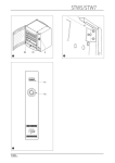
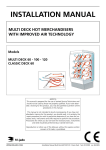
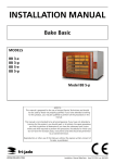
MC USER MANUAL Modular Counter Models: Cold Hot Ambient Base Warmer MC 75/100 C SS/FS MC 75/100 H SS/FS MC 75/100 A SS/FS MC 75/100 BW MC 100 Ambient MC100 Base Warmer EN (Original Instruction) 9123964 / 1305 MC KEEP THIS USER MANUAL FOR FUTURE USE © 2013 Fri-Jado BV, Etten-Leur, The Netherlands. We advise you to contact your supplier for the guarantee period and conditions. Further we refer to our General Terms and Conditions for Sales and Delivery that are available upon request. The manufacturer does not accept any liability for damage or injury caused by failing to adhere to these regulations or by not observing the usual caution or care in actions, operation, maintenance or repair activities, even if not explicitly described in this manual. As a result of constant commitment to improvement, it may happen that your unit deviates in detail from what is described in this manual. For this reason, the given instructions are only a guideline for the installation, use, maintenance and repair of the unit referred to in this manual. This manual has been composed with the utmost care. The manufacturer shall, however, not be held responsible for any mistakes in this manual nor for any consequences thereof. The user is allowed to copy this manual for own use. Further all rights are reserved and nothing in this manual may be reproduced and/or made public in any way. Modifications: In case of unauthorized modifications in or on the unit, every liability on the part of the manufacturer becomes null and void. 2/24 9123964 / 1305 MC CONTENTS 1. INTRODUCTION ......................................................................................................... 5 1.1. General ........................................................................................................................... 5 1.2. Identification of the unit ................................................................................................ 5 1.3. Pictograms and symbols.............................................................................................. 5 1.4. Safety instructions ........................................................................................................ 6 1.4.1. General ....................................................................................................................... 6 1.4.2. Moving ........................................................................................................................ 6 1.4.3. Outdoor use restrictions........................................................................................... 7 2. 3. 1.5. Hygiene .......................................................................................................................... 7 1.6. Service and technical support ..................................................................................... 7 1.7. Storage ........................................................................................................................... 7 1.8. Disposal .......................................................................................................................... 7 DESCRIPTION OF THE UNIT .................................................................................... 8 2.1. Technical description.................................................................................................... 8 2.2. Intended use .................................................................................................................. 9 2.3. Accessories ................................................................................................................... 9 INSTALLATION AND FIRST USE ........................................................................... 10 3.1. Unpacking the unit ...................................................................................................... 10 3.2. Installation and positioning ........................................................................................ 10 3.2.1. Mounting the plinth. ................................................................................................ 10 3.2.2. Mounting the side panel......................................................................................... 11 3.2.3. Connecting two Modular Counter Units............................................................... 12 3.2.4. Applying a price tag ................................................................................................ 13 3.2.5. Drain (Base Warmer) ............................................................................................. 13 3.3. 4. First use........................................................................................................................ 13 OPERATION AND USE ............................................................................................ 14 4.1. Cold Unit....................................................................................................................... 14 4.1.1. Control Panel ........................................................................................................... 14 4.1.2. Switching-on the unit .............................................................................................. 14 4.1.3. Loading the unit....................................................................................................... 14 4.1.4. Checking the temperature ..................................................................................... 14 4.1.5. Checking the SET temperature ............................................................................ 14 4.1.6. Adjusting the set Temperature.............................................................................. 15 4.1.7. Switching off ............................................................................................................ 15 4.1.8. Thaw ......................................................................................................................... 15 4.2. Hot Unit......................................................................................................................... 15 3/24 9123964 / 1305 MC 4.2.1. Control panel ........................................................................................................... 15 4.2.2. Switching-on the unit .............................................................................................. 16 4.2.3. Loading the unit....................................................................................................... 16 4.2.4. Checking the temperature in the unit ................................................................... 16 4.2.5. Checking the SET temperature ............................................................................ 16 4.2.6. Adjusting the set Temperature.............................................................................. 16 4.2.7. Checking the product temperature....................................................................... 16 4.2.8. Switching off ............................................................................................................ 16 4.3. Ambient Unit ................................................................................................................ 17 4.3.1. Control panel ........................................................................................................... 17 4.3.2. Switching-on the unit .............................................................................................. 17 4.3.3. Loading the unit....................................................................................................... 17 4.3.4. Switching off ............................................................................................................ 17 4.4. Base Warmer............................................................................................................... 18 4.4.1. Control panel ........................................................................................................... 18 4.4.2. Prepare the unit....................................................................................................... 18 4.4.3. Switching-on the unit .............................................................................................. 18 4.4.4. Setting the temperature ......................................................................................... 18 4.4.5. Checking the water level........................................................................................ 18 4.4.6. Loading the unit....................................................................................................... 18 4.4.7. Switching off the unit .............................................................................................. 18 5. CLEANING AND MAINTENANCE ........................................................................... 19 5.1. Maintenance schedule ............................................................................................... 19 5.2. Daily Cleaning ............................................................................................................. 19 5.2.1. Thaw (Cold Unit) ..................................................................................................... 19 6. 7. 5.3. Weekly Cleaning ......................................................................................................... 19 5.4. Cleaning the condenser (Cold Unit) ......................................................................... 20 MALFUNCTIONS AND SERVICE ............................................................................ 21 6.1. Replace a lamp ........................................................................................................... 21 6.2. Replace the mains cord ............................................................................................. 21 TECHNICAL SPECIFICATIONS .............................................................................. 22 7.1. Cold Unit....................................................................................................................... 22 7.2. Hot Unit......................................................................................................................... 22 7.3. Ambient Unit ................................................................................................................ 23 7.4. Base Warmer............................................................................................................... 23 4/24 9123964 / 1305 MC 1. 1.1. INTRODUCTION General This manual is intended for the user of the MC (Modular Counter). The features and controls are being described, along with directions for the safest and most efficient use, in order to guarantee a long life of the unit. All pictograms, symbols and drawings in this manual apply to all available MC models. 1.2. Identification of the unit The identification plate can be found on the outside of the machine, and contains the following data: • Name of the supplier or the manufacturer • Model • Serial number • Year of construction • Voltage • Frequency • Power consumption 1.3. Pictograms and symbols In this manual, the following pictograms and symbols are used: WARNING Possible physical injury or serious damage to the unit, if the instructions are not carefully followed. WARNING Hazardous electrical voltage. WARNING Danger of getting injured by hot surfaces. Suggestions and recommendations to simplify indicated actions. Recycling symbol. 5/24 9123964 / 1305 MC 1.4. Safety instructions WARNING The outside and shelves of the unit can be very hot. WARNING The maximum load on top of the unit may never exceed 10 kg. 1.4.1. General The user of the unit will be fully responsible for abiding the locally prevailing safety- rules and regulations. The unit may be operated by qualified and authorized persons only. Anyone working on or with this unit must be familiar with the contents of this manual and carefully follow all guidelines and instructions. Never change the order of the steps to be performed. The management must instruct the personnel on the basis of this manual and follow all instructions and regulations. The pictograms, labels, instructions and warning signs attached to the unit, are part of the safety measures. They may never be covered or removed, and have to be clearly visible during the entire lifetime of the unit. Immediately repair or replace damaged or illegible pictograms, warnings and instructions. • • • • • 1.4.2. To avoid short-circuiting, never clean the unit using a water hose. For cleaning instructions, see section 5. The shelves, columns and back of the hot unit can get hot. The unit must be cleaned regularly to ensure proper functioning. This appliance is not intended for the use by persons (including children) with reduced physical, sensory or mental capabilities, or lack of experience and knowledge, unless they have been given supervision or instruction concerning use of the appliance by a person responsible for their safety. Children should be supervised to ensure that they do not play with the appliance. Moving When moving the unit: • Before moving the unit, first switch off the mains voltage by pulling the plug from the wall socket. • Remove pans containing a liquid product from the unit. • The units equipped with wheels are not suited to pass ledges or obstacles higher than 10 mm. • When moving the unit, always push at the center of the unit. Never on top. Never at the bottom. • Make sure that the wheels can move freely, so they never touch the power lead. 6/24 9123964 / 1305 MC 1.4.3. • Outdoor use restrictions To avoid short-circuiting, the units may not be used outdoors or in a rainy or very moist environment. If setting the unit up outdoors, first contact your supplier. • 1.5. Hygiene WARNING Immediately remove products in damaged packaging from the equipment. Destroy the products. Clean all components that that have come in contact with products from damaged packaging. The quality of a fresh product always depends on hygiene. Especially grilling products. With the risk of salmonella contamination – especially for chicken products – you must make sure that grilled products can never be mixed with uncooked products. Also contact between grilled products and hands or tools that have been in contact with raw chicken meat, must be avoided at all times. Hands or tools that have been in contact with raw chicken meat, must be cleaned thoroughly. 1.6. Service and technical support The electrical schematics of your unit is included. In case of malfunctions you can contact your dealer/service agent. Make sure you have the following data available: • • Model. Serial number. This data can be found on the identification plate. 1.7. Storage If the unit will not be used temporarily, and will be stored, follow these instructions: • Clean the unit thoroughly. • Wrap the unit from getting dusty. • Store the unit in a dry, non-condensing environment. 1.8. Disposal Dispose of the machine, any components or lubricants removed from it safely in accordance with all local and national safety and environment requirements. 7/24 9123964 / 1305 MC 2. 2.1. DESCRIPTION OF THE UNIT Technical description The panels are made of galvanized steel plating, stainless steel or aluminum. The visible internal and external parts have been provided with a powder coating. The glass used is tempered. The unit can move by means of four non braking castors. The heating and lighting switches have been mounted on the back. The product contact parts are made of stainless steel AISI 304 or AISI 430 and tempered glass. Cold unit: Cooling is achieved by means of a thermostatic temperature-controlled cold airflow. The temperature of the airflow is controlled electronically. Lighting is by three TL lights with shatterproof coating. The Modular Counter Cold uses a cooling unit and an evaporator, built in at the base. The evaporator is situated in the space beneath the bottom plate. The cold air is passed via the back and shelves over the products. The air on the front side passes through the suction grid in the bottom of the unit, behind the front. This way the warm air is kept out of the unit. The electronically-controlled thermostat is factory programmed for the correct temperature. The set temperature can be changed from 2,5 °C to -2,5°C for the full service models and from 3°C to -3°C for the self-service models. Any water generated is evaporated automatically by a condensation water evaporation unit. Lighting and cooling is switched on separately. The self-service models are not accommodated with a night curtain. Hot unit: Heating is achieved by means of heated shelves in combination with an hot-air curtain per shelf. The air curtain isolates the hot air inside the unit from the ambient air. Lighting is done by three TL-lights with a shatterproof coating. The Modular Counter Hot makes use of heating elements inside the shelves, bottom shelf and top for heating. The heat from these elements will heat the double walled shelves and bottom shelf. The shelves and bottom shelf will conduct the heat to the products and surrounding air. An electronic thermostat controls the temperature. The electronic thermostat has been set at the correct value at the factory. This value can be changed between 55°C and 90°C. The TL-lighting and the heating are switched on and off separately. Ambient unit: Lighting is done by three TL-lights with a shatterproof coating. The switch on the back of the Modular Counter switches the lighting on and off. By opening the slide doors the shelves can be loaded or unloaded with products. The customer can take products from the shelves through the opening in the front of the Self Service model Modular Counter. The Full Service model Modular Counter has a closed front. Base Warmer Unit: Three warmer units are positioned in the base. Each unit is controlled separately. The mains is distributed inside. 8/24 9123964 / 1305 MC 2.2. Intended use The unit has been designed solely to keep packaged products warm, cold and or to display them. Any other use will not be regarded as intended use. The manufacturer accepts no liability whatsoever for loss or injury caused by failing to strictly adhere to the safety guidelines and instructions in this manual or due to carelessness during installation, use, maintenance and repair of the unit referred to in this manual and any of its accessories. Use the unit in perfect technical condition only. 2.3. Accessories Your unit contains the following standard accessories: • User manual. • Brackets to link two units (depending on type). • Plinth set. • Drain valve (Base warmer only) 9/24 9123964 / 1305 MC 3. INSTALLATION AND FIRST USE 3.1. • • Unpacking the unit Remove the foil from all metal parts (if present). Remove all packaging materials from the unit. All packing materials used for this unit are suited for recycling. After unpacking, check the state of the unit. In case of damage, store the packing material, and contact the transporter within fifteen working days after receiving the goods. 3.2. • • • • • • • • • 3.2.1. Installation and positioning Place the unit level on a sufficiently sturdy floor. Keep the weight of the unit in mind. Use a leveling instrument to level the unit to water level. Be sure that the personnel have sufficient room to work with the unit. Keep a distance of at least 40 cm (16 inch) between the back wall and the unit. While positioning, keep the unit out of children’s reach. Do not position a unit near a doorway, a ventilation device or a refrigerator in order to avoid any negative effects on the unit’s operation by a cold airflow. The unit is designed for a maximum draft of 0,2 m/s. Do not place into direct sunlight. Be sure that the ambient temperature remains between 20 - 22 °C and that the air humidity remains between 60 % - 65 %. The unit has a mains plug, and must be connected to a wall socket with the proper mains voltage. The wall socket must be mounted by a certified electrician. Keep the plinth free from any obstacles to ensure ventilation. Mounting the plinth. Place the unit on a sturdy, flat surface and adjust the four legs until the unit is at horizontal level. The unit must rest on all four legs. Figure 1 10/24 9123964 / 1305 MC Place the plinth with the cams into the recesses and pinch the plinth on the front legs. Figure 2 3.2.2. Mounting the side panel Loosen the screws on the side of the back and keep them on a safe place for fastening the side panel. Figure 3 Slide the side panel from the back to the front into the unit. Take care that the upper rim of the side panel fits into the guiding and that the front edge fits inside the bottom panel. Figure 4 11/24 9123964 / 1305 MC Fasten the three screws. Figure 5 3.2.3. Connecting two Modular Counter Units The Modular Counter can be connected sideways to another Modular Counter Unit. Remove the side panel of the connecting sides if a side panel has been fitted. Loosen the screws on the side of the back and keep them on a safe place for fastening the connecting panel. This must be performed on both units . Figure 6 Place the unit on a sturdy, flat surface and adjust the four legs until the unit is at horizontal level. The unit must rest on all four legs Place the other unit next against the First unit and adjust the four legs until the unit is at horizontal level. The unit must rest on all four legs and the height of both units must comply. Figure 7 12/24 9123964 / 1305 MC Mount the connecting panel to both units and fasten the six screws. Figure 8 3.2.4. Applying a price tag The plastic price rail must be used for applying price tags. This can be done without taking the shelf from the unit. Open the underside of the price rail and slide the price tag from below into the price rail. Figure 9 3.2.5. Drain (Base Warmer) Provide a drain system to the drain valves. 3.3. First use WARNING Cold unit: Following installation, wait at least half an hour before you switch the unit on, to achieve good lubrication of the compressor. Before starting to use the unit clean the inside thoroughly with mild detergent and water. After cleaning it wipe it with a cloth moistened with clean water to remove detergent residual, then dry the entire unit. 13/24 9123964 / 1305 MC 4. OPERATION AND USE 4.1. Cold Unit 4.1.1. Control Panel A1 A2 A3 A4 A5 A6 A7 Indication ON Display temperature UP-button SET-button DOWN-button Cooling Switch Lighting Switch Indication ON will light when the cooling is active. Figure 10 4.1.2. Switching-on the unit The cold unit is factory programmed to achieve a product temperature of ≤7 ºC at an ambient of 22°C with a humidity of 65% and a max. draft of 0.05m/s. The set temperature can be changed from -2,5 °C to +2,5°C for the full service models and from 3°C to -3°C for the self-service models. Switch the cooling on. Let the unit cool for approx. 30 minutes. Switch the lighting. 4.1.3. Only load packaged products of which the maximum temperature is max. 4 ºC. The maximal loading height on the top shelf is 100 mm., on the other shelves 150 mm. The maximum carrying-capacity per shelf is 30 kg, by equal load. 4.1.4. Checking the temperature During operation the display of the thermostat shows the temperature 1 in the unit. The maximum reading must not exceed 5 ºC. The indication ON will light when the cooling is active. 4.1.5. Loading the unit Checking the SET temperature During operation the display of the thermostat shows the temperature 2 in the unit. Push once on the SET-button (A4). The set temperature will appear on the display. The display will show the temperature in the unit after 20 seconds. 1 2 Note: The display and or set value is not the product/unit temperature. Note: The display and or set value is not the product/unit temperature. 14/24 9123964 / 1305 MC 4.1.6. During operation the display of the thermostat shows the temperature 3 in the unit. Push once on the SET-button (A4). The set temperature will appear on the display. Adjust the set temperature by means of the UP-button (A3) and the Down-button (A5). Push once on the SET-button (A4) to store the new set temperature. 4.1.7. Switching off Remove all products from the unit. In order to avoid temperature rise of the products, store them in another cooling unit. Switch the cooling off. Switch the lighting off. 4.1.8. Adjusting the set Temperature Thaw To prevent the unit from freezing in, the unit has to thaw. Switch off the unit for at least 3 hours every 24 hours 4.2. Hot Unit 4.2.1. Control panel A1 A2 A3 A4 A5 A6 A7 Indication ON Display temperature UP-button SET- button DOWN-button Heating Switch Lighting Switch Indication ON will light when the heaters are active, Figure 11 3 Note: The display and or set value is not the product/unit temperature. 15/24 9123964 / 1305 MC 4.2.2. Switching-on the unit The unit is set at 75°C for the serve over model and 85°C for the self-service model. At a ambient temperature of 20°C and an initial core temperature of 85°C these factory settings of the unit’s temperature ensure a constant core temperature of at least 63°C for 4 hours. If required the temperature can be changed between 55°C and 90°C. Switch the heating on. Preheat the unit for approx. 30 minutes. Switch on the lighting. 4.2.3. Only place packaged products that have a core temperature of at least 85°C. Only package the hot products in bags or containers that are suitable for this purpose. To ensure a good contact with the heated trays, only place a single layer of products. 4.2.4. Checking the product temperature. Once every hour, the product temperature should be checked using a digital thermometer. Write down the measured values in a log. Always use a disinfected thermometer sensor. 4.2.8. Adjusting the set Temperature During operation the display of the thermostat shows the temperature 5 in the unit. Push once on the SET-button (A4). The set temperature will appear on the display. Adjust the set temperature by means of the UP-button (A3) and the Down-button (A5). Push once on the SET-button (A4) to store the new set temperature. 4.2.7. Checking the SET temperature During operation the display of the thermostat shows the temperature 4 in the unit. Push once on the SET-button (A4). The set temperature will appear on the display. The display will show the temperature in the unit after 20 seconds. 4.2.6. Checking the temperature in the unit During operation the display of the thermostat shows the temperature at the probe in the unit. The indication ON will light when the elements are active. 4.2.5. Loading the unit Switching off Remove all products from the unit. In order to avoid temperature drop of the products, store them in another warm holding unit. Switch the heating off. Switch the lighting off. 4 5 Note: The display and or set value is not the product/unit temperature. Note: The display and or set value is not the product/unit temperature. 16/24 9123964 / 1305 MC 4.3. 4.3.1. Ambient Unit Control panel A7 Lighting Switch Figure 12 4.3.2. Switch on the lighting. 4.3.3. Loading the unit The maximal loading height on the top shelf is 100 mm., on the other shelves 150 mm. The maximum carrying-capacity per shelf is 30 kg, by equal load. 4.3.4. Switching-on the unit Switching off Remove all products from the unit. Switch the lighting off. 17/24 9123964 / 1305 MC 4.4. 4.4.1. Base Warmer Control panel A1 A1 Thermostat A2 ON/OFF switch A2 Figure 13 4.4.2. Fill the well pan with 20 mm of water (approx. 1 liter) 4.4.3. Loading the unit Place the inner pan with preheated product in the well pan. Do not fill the well pan with product. 4.4.7. Checking the water level Verify each three hours the water level. If necessary, fill to about 20 mm (1 litre). If the Well pan no longer contains water let it cool down before re-filling. 4.4.6. Setting the temperature Turn the thermostat fully clockwise. When the product boils turn the thermostat slightly counter clockwise. The correct position must be determined experimentally. TIP use the preheated inner pan with the lid added 4.4.5. Switching-on the unit Switch on the unit by pressing the ON/OFF switch (the button will lit). 4.4.4. Prepare the unit Switching off the unit Switch off the unit by pressing the ON/OFF switch. Remove the inner pan. Remove or drain the heated water. Dry the well pan with a clean cloth. 18/24 9123964 / 1305 MC 5. CLEANING AND MAINTENANCE WARNING Never use a water hose for cleaning. Water can seep into the unit through the ventilation holes of the unit. Because of hygiene aspects and optimum condition of the unit it is of utmost importance to keep a daily cleaning pattern from first use onwards. 5.1. Maintenance schedule Item Inside Cooling section Glass panes Outside Condenser 5.2. - 5.2.1. - 5.3. Action • Clean, see section 5.2. • Thaw, see section 5.2.1. • Clean , see section 5.3. • Clean , see section 5.3. • Use Stainless Steel cleaning spray to remove stains, and restoring the gloss. • Clean , see section 5.4. Frequency Daily Daily Weekly Weekly Monthly Daily Cleaning Clean the inside of the unit with hot water and a suitable cleaner. After cleaning wipe the inside with a clean wet cloth. Be sure that the detergent is removed properly. Thaw (Cold Unit) Switch off the unit for at least 3 hours every 24 hours to thaw the unit. Weekly Cleaning WARNING The control panel may only be cleaned using a damp cloth. - Clean the outside of the unit with a small amount of hot water and a mild cleanser and using a soft brush or sponge. After cleaning it dry the outside with a cloth. Treat all cleaned surfaces with a suitable antibacterial agent. Rub dry with a soft cloth or a paper towel. 19/24 9123964 / 1305 MC 5.4. Cleaning the condenser (Cold Unit) Remove the ventilation grid in front of the condenser unit. Clean the condenser using a long haired soft brush. Figure 14 Figure 15 Replace the ventilation grid. 20/24 9123964 / 1305 MC 6. MALFUNCTIONS AND SERVICE Before you consult your dealer or the service agency when there is a fault, you can check the following points yourself: • • Is the power supply OK? Check the fuses and the earth leakage switch in the meter cupboard. Are all the switches in the correct position? Item Control Malfunction Unit do not work Control Display shows code E1, E2, E3 Lamp Does not light up Mains cord Window Damaged Damaged 6.1. Possible action • Check the power supply. • Are all switches in the correct position. • Contact your supplier or service agency. • Switched OFF. • Defect, refer to section 6.1. • Replace, see section 6.2 • Replace, contact your supplier or service agency. Replace a lamp WARNING Remove the power plug from the wall socket. 1. Switch off the unit. 2. Remove the power plug from the wall socket. 3. Remove the broken lamp by turning the lamp 90 ° and slide it vertically out of the holder. 4. Replace the lamp by a similar type. 6.2. Replace the mains cord WARNING Hazardous electrical voltage. If the mains cord is damaged, it must be replaced by the manufacturer, his service agent or a similarly qualified person in order to avoid hazards. 21/24 9123964 / 1305 MC 7. TECHNICAL SPECIFICATIONS WARNING Consult the identification plate to get the proper specifications of the unit. The electrical data may vary from country to country. 7.1. Cold Unit Model Measurements ▪ Width ▪ Depth ▪ Height Weight ▪ Net Approx. Ambient ▪ Temperature ▪ Relative humidity Electrical Installation ▪ Voltage ▪ Max. nominal Current ▪ Plug ▪ Length power cord Noise level (at workplace) Refrigerant* Class (EN-ISO 23953-2) * MC 75 C MC 100 C 750 mm 765 mm 1525 mm 1000 mm 765 mm 1525 mm 160 Kg 180 Kg min. 20°C, max. 22°C max. 65% min. 20°C, max. 22°C max. 65% 1N~ 230V 50 Hz. 8.5A 2 pole earthed plug 1,5 m <70 dB(A) 1N~ 230V 50 Hz. 8.5A 2 pole earthed plug 1,5 m <70 dB(A) 2M2 2M2 Because a coolant has be used which complies with the environmental requirements valid at the moment of manufacture of the appliance, the type and filling weight are indicated on the data plate or on the cooling unit. 7.2. Hot Unit Model Measurements ▪ Width ▪ Depth ▪ Height Weight ▪ Net approx. Ambient ▪ Temperature ▪ Relative humidity Electrical installation ▪ Voltage ▪ Max. nominal current ▪ Plug ▪ Cable length Noise level (at workplace) MC 75 H MC 100 H 750 mm 765 mm 1525 mm 1000 mm 765 mm 1525 mm 136 Kg 167 Kg min. 20°C, max. 35°C min. 20%, max. 85% min. 20°C, max. 35°C min. 20%, max. 85% 1N~ 230V 50 Hz. 13 A 2 pole earthed plug 1,5 m <70 dB(A) 1N~ 230V 50 Hz. 13 A 2 pole earthed plug 1,5 m <70 dB(A) 22/24 9123964 / 1305 MC 7.3. Ambient Unit Model Measurements ▪ Width ▪ Depth ▪ Height Weight ▪ Net approx. Electrical Installation ▪ Voltage ▪ Max. nominal Current ▪ Plug ▪ Length power cord Noise level (at workplace) 7.4. MC 75 A MC 100 A 750 mm 765 mm 1525 mm 1000 mm 765 mm 1525 mm 110 Kg 135 Kg 1N~ 230V 50 Hz. 0.3 A 2 pole earthed plug 1,5 m <70 dB(A) 1N~ 230V 50 Hz. 0.3 A 2 pole earthed plug 1,5 m <70 dB(A) MC 75 BW MC 100 BW 750 mm 743 mm 1025 mm 1000 mm 743 mm 1025 mm 90 Kg 95 Kg 1N~ 230V 50 Hz. 3.5 A 2 pole earthed plug 1,5 m <70 dB(A) 1N~ 230V 50 Hz. 5.2 A 2 pole earthed plug 1,5 m <70 dB(A) Base Warmer Model Measurements ▪ Width ▪ Depth ▪ Height approx. Weight ▪ Net approx. Electrical Installation ▪ Voltage ▪ Max. nominal Current ▪ Plug ▪ Length power cord Noise level (at workplace) 23/24 9123964 / 1305 MC Fri-Jado BV Oude Kerkstraat 2 4878 AA Etten-Leur The Netherlands Tel: +31 (0) 76 50 85 400 Fax: +31 (0) 76 50 85 444 24/24 9123964 / 1305