1
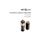
Combination
Fluorometer and
Turbidity Sensor
ECO FLNTU
User’s Guide
The user’s guide is an evolving document. If you find sections that are unclear, or missing
information, please let us know. Please check our website periodically for updates.
WET Labs, Inc.
P.O. Box 518
Philomath, OR 97370
541-929-5650
fax: 541-929-5277
www.wetlabs.com
ECO FLNTU User’s Guide (flntu)
Revision Z
13 May 2009
ECO Sensor Warranty
This unit is guaranteed against defects in materials and workmanship for one year from the
original date of purchase. Warranty is void if the factory determines the unit was subjected to
abuse or neglect beyond the normal wear and tear of field deployment, or in the event the
pressure housing has been opened by the customer.
To return the instrument, contact WET Labs for a Return Merchandise Authorization (RMA)
and ship in the original container. WET Labs is not responsible for damage to instruments
during the return shipment to the factory. WET Labs will supply all replacement parts and labor
and pay for return via 3rd day air shipping in honoring this warranty.
Shipping Requirements
1. Please retain the original Pelican® shipping case. It meets stringent shipping and insurance
requirements, and protects your meter.
2. Service and repair work cannot be guaranteed unless the meter is shipped in its original case.
3. Clearly mark the RMA number on the outside of your case and on all packing lists.
4. Return instruments using 3rd day air shipping or better: do not ship via ground.
Return Policy for Instruments with
Anti-fouling Treatment
WET Labs cannot accept instruments for servicing or repair that are treated with anti-fouling
compound(s). This includes but is not limited to tri-butyl tin (TBT), marine anti-fouling paint,
ablative coatings, etc.
Please ensure any anti-fouling treatment has been removed prior to returning instruments to
WET Labs for service or repair.
ECO FLNTU User’s Guide (flntu)
Revision Z
13 May 2009
Table of Contents
1.
Specifications ............................................................................. 1
2.
ECO Meter Components ............................................................ 3
2.1 Connectors .......................................................................................................................... 3
2.2 Delivered Items .................................................................................................................. 4
2.3 Optional Equipment ........................................................................................................... 4
3.
Theory of Operation .................................................................... 7
4.
Instrument Operation .................................................................. 8
4.1
4.2
4.3
4.4
4.5
5.
Initial Checkout .................................................................................................................. 8
Operating the Sensor for Data Output ................................................................................ 8
Bio-wiper™ Operation ....................................................................................................... 9
Deployment ........................................................................................................................ 9
Upkeep and Maintenance .................................................................................................. 10
FLNTUB: Using Internal Batteries ............................................. 13
5.1 Removing End Flange and Batteries ................................................................................ 13
5.2 Replacing End Flange and Batteries ................................................................................ 14
5.3 Checking Vent Plug.......................................................................................................... 15
6.
Data Analysis............................................................................ 16
6.1 Scale Factor ...................................................................................................................... 16
6.2 Analog Response .............................................................................................................. 16
6.3 Digital Response............................................................................................................... 17
7.
Characterization and Testing .................................................... 18
8.
Terminal Communications ........................................................ 19
8.1 Interface Specifications .................................................................................................... 19
8.2 Command List .................................................................................................................. 19
9.
9.1
9.2
9.3
9.4
9.5
Device and Output Files ........................................................... 20
Plot Header ....................................................................................................................... 20
Column Count Specification ............................................................................................ 20
Column Description ......................................................................................................... 20
Sample Device Files ......................................................................................................... 21
Sample Output Files ......................................................................................................... 21
Appendix A: Mounting Bracket Drawing ................................................. 22
ECO FLNTU User’s Guide (flntu)
Revision Z
13 May 2009
i
1.
Specifications
Model
Mechanical
FLNTU(RT)/D
FLNTU
FLNTUB
Diameter
FLNTUSB
13.3 cm
26.0 cm
6.3 cm
Length
6000 m
FLNTUS
12.7 cm
25.4 cm
10.1 in (25.6 cm)
Weight in air
6000 m
Weight in water
6000 m
--
0.4 kg
0.96 kg
0.5 kg
0.96 kg
1.3 kg
--
--
--
0.02 kg
0.14 kg
0.08 kg
0.14 kg
0.75 kg
--
Material, std depth
Acetal copolymer
6000 m
Titanium
--
Environmental
Temperature range
0–30 deg C
Depth rating
600 m
“deep” unit
300 m
6000 m
--
Optional pressure sensor
N
Y
Yes
Optional thermistor
N
Y
Yes
Electrical
Digital output resolution
12 bit
Analog output signals
0–5 V
Internal data logging
N
Internal batteries
Y
N
Y
Y
Connector
N
Subconn MCBH6M
Input
7–15 VDC
Current, typical
60 mA
Current, sleep
--
150 µA
Data memory
--
65,000 samples
Sample rate
RS-232 output
Optional Anti-fouling
bio-wiper™
Bio-wiper™ cycle
Y
to 8 Hz
19200 baud
N
Y
--
140 mA
Optical (Turbidity)
Wavelength
700 nm
Sensitivity (min)
0.01 NTU
Range, typical
0.01–25 NTU
Optical (Fluorescence)
Wavelength excitation
470 nm
Wavelength emission
695 nm
Sensitivity (per count)
0.01 µg/l
Range, typical
0.01–50 µg/l
2
Linearity (both signals)
ECO FLNTU User’s Guide (flntu)
99% R
Revision Z
13 May 2009
1
FLNTU(RT)—Provides analog or RS-232 serial output with 4,000-count range. This unit
operates continuously when powered. Available with a 6,000 m depth rating.
FLNTU—Provides the capabilities of the FLNTU(RT) with periodic sampling. Available with
a 6,000 m depth rating.
FLNTUS—Provides the capabilities of the FLNTU with an integrated anti-fouling bio-wiper™
and copper faceplate.
FLNTUB—Provides the capabilities of the FLNTU with internal batteries for autonomous
operation.
FLNTUSB—Provides the capabilities of the FLNTUS with internal batteries for autonomous
operation.
2
ECO FLNTU User’s Guide (flntu)
Revision Z
13 May 2009
2.
ECO Meter Components
The following subsections describe the bulkhead connectors, items delivered with the ECO
sensor, and optionally available equipment.
2.1
Connectors
ECO-Series meters use a six-pin bulkhead connector.
Pin
Function
1
2
3
4
5
Ground
RS-232 RX
NTU analog out
V in
RS-232 TX
6
FL analog out
MCBH-6-MP
Input power of 7–15 VDC is applied to V in (pin 4). The power supply current returns
through the common ground pin (pin 1). The input power signal has a bi-directional filter.
This prevents external power supply noise from entering into ECO-FLNTU, and also
prevents internally generated noise from coupling out on to the external power supply wire.
Data is sent out the serial output pin.
2.1.1 ECO FLNTUB, FLNTUSB Connectors
FLNTUB and FLNTUSB (units with internal batteries) have a second bulkhead
connector that comes with a jumper plug to supply power to the unit. The pin functions
for this connector are shown below.
ECO FLNTUB and FLNTUSB connector schematic
ECO FLNTU User’s Guide (flntu)
Revision Z
13 May 2009
3
Pinout summary for ECO FLNTUB/FLNTUSB
Socket
1
2
3
Function
V in
N/C
Battery out
FLNTUB and FLNTUSB (internal battery units) are supplied with a jumper plug that
provides power from the internal batteries for autonomous operation.
2.2
Delivered Items
The standard ECO delivery consists of the following:
• the instrument itself
• dummy plug with lock collar
• protective cover for optics
• this user’s guide
• ECOView user’s guide
• ECOView host program and device files (on CD)
• instrument-specific calibration sheet
• Non-battery units only: stainless steel mounting bracket and hardware (See Appendix A
for details)
• Internal battery units: six 9-V Lithium batteries (installed)
Spare Parts (equipment-dependent)
• Fluorescent stick for bench testing
• Bio-wiper™ units: one 3/32-in. hex key for bio-wiper™ removal
• Bio-wiper™ units: Three 4-40 x 3/8 in. 316 stainless steel screws for securing bio-wiper™
• Internal battery units:
o Two end flange O-rings (size 224) and two vent plug O-rings (size 010)
o Two jacking screws for connector flange removal
o One 3/32-in. hex key for jacking screws
o Power plug for autonomous operation
o Three pre-cut segments (7 inches) of 0.036-inch diameter monofilament for end flange
o Three pre-cut segments (0.25 inches) of 0.094-inch diameter white nylon bar stock
for replacing the white plastic dowel pin.
2.3
Optional Equipment
2.3.1 Test Cable
A test cable is optionally available with each unit. This cable includes:
1. An inline connector for providing power to the instrument from a user-supplied 9V
battery.
2. An auxiliary analog out connector.
3. A second auxiliary analog out connector for NTU only.
4. A DB-9 serial interface connector.
5. A six-socket connector for providing power and signal to the instrument.
4
ECO FLNTU User’s Guide (flntu)
Revision Z
13 May 2009
2.3.2 Copper Faceplate
ECO meters are optionally equipped with copper faceplates to improve the meter’s
resistance to biofouling. Refer to Section 4.5.1 for important details on maintenance and
cleaning.
2.3.3 Bio-wiper™ and Copper Faceplate
The FLNTUS and FLNTUSB are equipped with an integrated non-contact anti-fouling
Bio-wiper™ and copper faceplate for use in extended deployments. This wiper can be
manually controlled by a host controller package, or can perform autonomously as part of
a pre-programmed sampling sequence upon instrument power-up. The rate of closure and
opening is dependent upon both temperature and depth.
Refer to Section 4.5.1 for important details on the maintenance and cleaning of the Biowiper™ and copper faceplate.
WARNING!
Do NOT rotate the Bio-wiper™ manually. This can damage the wiper motor and will
void the warranty.
2.3.4 Batteries
ECO units with internal batteries are supplied with six 9-volt Lithium batteries as their
power source. They can use either standard alkaline cells for a total capacity of
approximately 1000 mA-hrs, or for longer deployments, LiMnO2 cells to achieve more
than 2000 mA-hrs of operational capacity. Actual total usage time of the internal
batteries is a function of several parameters. These include nominal water temperature,
sequence timing, sample periods, and total deployment duration.
WARNING!
Be sure to keep the dummy plug on the FLNTUB and FLNTUSB when not in use.
For even greater deployment capability contact WET Labs for information on external
battery packs.
2.3.5 External Thermistor
ECO meters are optionally equipped with an external thermistor. The thermistor is
calibrated at WET Labs and the calibration coefficients are supplied on the instrument’s
calibration sheets. Thermistor output is in counts and can be converted into engineering
units using the instrument’s device file and ECOView software or the raw data can be
converted in the user’s software (e.g. MATLAB or Excel) using the calibration equation:
Temperature (deg C) = (Output * Slope) + Intercept
2.3.6 Pressure Sensor
ECO meters are optionally equipped with a strain gauge pressure sensor. The pressure
sensor is calibrated at WET Labs and the calibration coefficients are supplied on the
instrument’s calibration sheets. Pressure sensor output is in counts and can be converted
into engineering units using the instruments device file and ECOView software or the
ECO FLNTU User’s Guide (flntu)
Revision Z
13 May 2009
5
raw data can be converted in the user's software (e.g. MATLAB or Excel) using the
calibration equation:
Relative Pressure (dbar) = (Output * Slope) + Intercept
Please note that strain gauge pressure sensors are susceptible to atmospheric pressure
changes and should be “zeroed” on each deployment or profile. The calibration equation
for pressure above should be used first to get the relative pressure and the cast offset
should then be subtracted to get the absolute pressure:
Absolute Pressure (dbar) = Relative Pressure (dbar) - Relative Pressure at
Atmospheric/Water interface (dbar)
WARNING!
Do not exceed the pressure sensor’s depth rating (see calibration sheet).
Pressure Sensor Maintenance
A plastic fitting filled with silicone oil provides a buffer between the pressure
transducer and seawater. The transducer is both sensitive and delicate. Following the
procedures below will ensure the best results and longest life from your pressure
sensor.
Pressure is transmitted from the water to the stainless steel transducer diaphragm via
a plastic fitting filled with silicone oil. The inert silicone oil protects the pressure
sensor from corrosion, which would occur after long exposure to salt water. The
fitting will generally prevent the oil from escaping from the reservoir into the water.
However, you may occasionally wish to ensure that oil remains in the reservoir on top
of the transducer.
WARNING
Never touch or push on the transducer.
1. Thoroughly clean the top of the instrument.
2. Completely remove the white nylon Swagelock fitting using a 9/16-in. wrench.
3. Check for obstructions in the tiny hole. Blow clear with compressed air or use a
small piece of wire.
4. Wipe clean the o-ring at the base of the Swagelock fitting.
5. Screw the Swagelock fitting into the end flange until finger tight.
6. Tighten it an additional 1/8 turn using a wrench only if necessary.
7. Wipe up any excess oil.
6
ECO FLNTU User’s Guide (flntu)
Revision Z
13 May 2009
3.
Theory of Operation
The Environmental Characterization Optics (ECO) combination fluorometer and turbidity
sensor allows the user to measure chlorophyll fluorescence at 470 nm and turbidity at 700 nm
within the same volume.
The fluorometer allows the user to monitor chlorophyll concentration by directly measuring the
amount of chlorophyll-a fluorescence emission from a given sample volume of water.
Chlorophyll, when excited by the presence of an external light source, absorbs light in certain
regions of the visible spectrum and re-emits a small portion of this light as fluorescence at longer
wavelengths. Two bright blue LEDs (centered at 455 nm and modulated at 1 kHz) provide the
excitation source. A blue interference filter is used to reject the small amount of red light emitted
by the LEDs. The blue light from the sources enters the water volume at an angle of
approximately 55–60 degrees with respect to the end face of the unit. Fluoresced light is received
by a detector positioned where the acceptance angle forms a 140-degree intersection with the
source beam. A red interference filter is used to discriminate against the scattered blue excitation
light. The red fluorescence emitted is synchronously detected by a silicon photodiode.
Turbidity is measured simultaneously by detecting the scattered light from a 700 nm LED at 140
degrees to the same detector used for fluorescence. The turbidity measurement is performed at
the same 140 degree angle as the chlorophyll fluorescence.
ECO FLNTU User’s Guide (flntu)
Revision Z
13 May 2009
7
4.
Instrument Operation
Please note that certain aspects of instrument operation are configuration-dependent. These are
noted where applicable within the manual.
4.1
Initial Checkout
Supplied from the factory, ECOs are configured to begin continuously sampling upon poweron. Electrical checkout of ECO is straightforward using the optional test cable.
Connect the 6-socket connector on the test cable to the instrument to provide power to the
LEDs and electronics (see Section 1 for a diagram of the pin-outs of ECO-FLNTU). Connect
the battery leads on the test cable to the 9V battery supplied with the meter. Light should
emanate from the meter.
4.1.1 Analog Option
Connect a digital multimeter (DMM) to the auxiliary leg of the test cable: the center of
the RCA connector provides analog out signal and the outside provides ground. Auxiliary
“chl” is the fluorometer output. Auxiliary “NTU” is the NTU output. With the sensor face
clean and dry the instrument should read approximately 0.050–0.095 VDC. The analog
signal will saturate at approximately 5 volts.
4.2
Operating the Sensor for Data Output
Note
ECO scattering meters are sensitive to AC light. Before making measurement,
turn AC lighting off.
1. Connect the 6-socket connector to the instrument to provide power to the LEDs and
electronics. Connect the DB-9 connector to a computer with the ECOView host program
installed on it.
WARNING!
Always use a regulated power supply to provide power to ECO sensors if not using the 9V
battery provided with the test cable: power spikes may damage the meter.
2. Start ECOView. Select the appropriate COM Port and Device File. Supply power to the
meter, then click on the Start Data button. Output will appear in the Raw Data window.
Test the instrument’s signal using the fluorescent stick. ECO is sensitive to room lighting;
for best results, perform test in ambient light only (turn off AC lighting). Remove the
protective cover. Hold the fluorescent stick 1–4 cm above the optical paths in an
orientation that maximizes exposure of the stick. (Parallel with the beams, not
intersecting them). The signal will increase toward saturation (maximum value on
characterization sheet). When applying power to sensors with a Bio-wiper™, it will open
and, depending on the settings, operate until you select Stop Data in ECOView (or input
!!!!! in a terminal program) The Bio-wiper™ will close and the instrument will await
the next command.
8
ECO FLNTU User’s Guide (flntu)
Revision Z
13 May 2009
3. If the sensor completes the requested samples (this is common for meters set up in
moored applications), it will go into sleep mode, and the meter will not light when power
is cycled. To “wake” the meter, click Stop Data five times at the rate of two times per
second immediately upon applying power. This interrupts the sensor, returning it to a
“ready” state, awaiting commands.
4. Check the settings for the ECO and change if necessary. ECOView factory settings for
continuous operation:
Set Number of Samples = 0
Set Number of Cycles = 0
Internal Memory=On
5. If the meter does not light after performing step 3, check the battery. Replace if
necessary, perform steps 2 and 3 to verify communication. If it still does not light, contact
WET Labs.
Refer to the ECOView User’s Guide for details about using the software.
4.3
Bio-wiper™ Operation
The ECO-FLNTUS and -FLNTUSB are provided with an anti-fouling bio-wiper™ and
faceplate that extend the possible deployment duration by retarding biological growth on the
instrument’s optical surface. The Bio-wiper™ covers the optical surface: 1) while the
instrument is in “sleep” mode; 2) when it has completed the number of samples requested;
and 3) when the user selects Stop Data in ECOView or types “!!!!!” in a terminal program.
When the meter wakes up, the optical surface is exposed by the Bio-wiper’s™ counterclockwise rotation.
If power is shut off in mid cycle, the Bio-wiper™ will reinitialize to the beginning of the
user-selected settings when power is applied again.
4.4
Deployment
WARNING!
FLNTUB and FLNTUSB:
Always check vent seal plug for full insertion immediately prior to deployment.
Caution
The FLNTU should be mounted so the LED source will not “see” any part of a cage or
deployment hardware. This will compromise the sensor’s output.
Once power is supplied to the ECO meter, the unit is ready for submersion and subsequent
measurements. Some consideration should be given to the package orientation. Do not face
the sensor directly into the sun or other bright lights. For best output signal integrity, locate
the instrument away from significant EMI sources.
ECO FLNTU User’s Guide (flntu)
Revision Z
13 May 2009
9
Other than these basic considerations, one only needs to make sure that the unit is securely
mounted to whatever lowering frame is used and that the mounting brackets are not damaging
the unit casing.
4.5
Upkeep and Maintenance
After each cast or exposure of the instrument to natural water, flush with clean fresh water,
paying careful attention to the sensor face. Use soapy water to cut any grease or oil
accumulation. Gently wipe clean with a soft cloth. The sensor face is composed of ABS
plastic and optical epoxy and can easily be damaged or scratched.
WARNING!
Do not use acetone or other solvents to clean the sensor.
4.5.1 Bio-wiper™ and Faceplate Cleaning and Maintenance
The Bio-wiper™ and the copper faceplate need to be removed from the meter for
thorough cleaning to maximize anti-fouling capability.
1. Be sure the meter is NOT powered or connected to a power source prior to
uninstalling the Bio-wiper™ and faceplate.
WARNING!
Manually turning the motor shaft can damage the wiper motor and will void the warranty.
Make sure the Bio-wiper™ is loosened from the shaft before attempting to rotate
the Bio-wiper™.
2. Remove bio-wiper™: Use the factory-supplied 3/32-in. hex key to loosen the screw
that secures the wiper to the shaft on the instrument. It may be necessary to remove
the screw from the clamping hole and screw it into the releasing hole, tightening it
just enough to free the Bio-wiper™ from the shaft.
releasing screw hole
clamping screw hole
3. Remove faceplate: Use a small Phillips screwdriver to remove the screws that attach
the plate to the optics head.
WARNING!
Be sure to retain and re-use the factory-installed screws as they are vented for
pressure compensation.
10
ECO FLNTU User’s Guide (flntu)
Revision Z
13 May 2009
4. Wash bio-wiper™ and/or copper faceplate with soapy water. Rinse and dry
thoroughly. Note the condition of the copper on the instrument side of the wiper. It is
normal for copper to corrode and turn green, especially after the instrument has been
removed from the water. This corrosion will slightly reduce the shutter’s anti-fouling
ability the next time it is deployed.
5. Buff each with a pad of green Scotch Brite® (or similar) until shiny.
6. Clean the bio-wiper™ shaft and the shaft hole using an isopropyl alcohol-saturated
cotton swab. Allow to dry.
7. Re-install faceplate.
8. Check the screw used to secure the bio-wiper to the shaft: a hex key must fit
snugly into the screw socket. If the socket is in any way compromised, use a
new screw (4-40 x 3/8 in. 316 stainless steel treated with anti-seize. These are
shipped as part of the meter’s spare parts kit.)
9. Slide the bio-wiper™ over the shaft. Be careful not to twist it on, thus rotating
the shaft. If the wiper does not slide on easily, insert the screw into the expander
hole, turning slowly until the bio-wiper™ slides easily onto the shaft.
10. Rotate the bio-wiper™ into the closed position.
11. Set the gap between the bio-wiper™ and the instrument face to 0.03 in. (0.8 mm).
An improperly set gap will either fail to clean the face or cause the motor to draw
excessive current.
To gauge 0.03 in., fold a piece of paper in
half, then in half again, then fold a third time,
creasing the edges. It’s now 8 sheets and
about 0.03 in. thick.
ECO FLNTU User’s Guide (flntu)
Revision Z
13 May 2009
11
Not enough flex.
Wiper may not be
effective.
Proper flex.
Too much flex.
Wiper maintains contact with
instrument face and
optical window.
Wiper may cause too much
friction, using excessive power.
12. Use the 3/32-in. hex key to tighten the screw to “finger-tight,” then snug an additional
quarter-turn.
13. Run the instrument to verify operation. The bio-wiper™ must rotate 180 degrees to
clear the optics before sampling, and 180 degrees to cover the optics after sampling.
14. If the wiper needs adjusting, loosen the screw, make any necessary adjustments, and
repeat steps 9 through 13 to ensure the wiper is performing properly.
12
ECO FLNTU User’s Guide (flntu)
Revision Z
13 May 2009
5.
FLNTUB: Using Internal Batteries
ECO sensors powered with internal batteries can either run directly from the internal
batteries or can operate from power supplied by an external DC power supply (7–15
volts). Internal-to-external source conversion is facilitated by a jumper plug that plugs
into the unit’s bulkhead connector. When inserted, the plug forms a connection from the
battery to the electronics power supply. By removing the plug, the instrument can be
powered and communicate via a test or deployment cable. Setup conditions, instrument
checkout, real-time operation, and data downloading are thus all achieved identically to
the methods prescribed for the FLNTU and FLNTUS units.
5.1
Removing End Flange and Batteries
WARNING!
Changing the batteries will require opening the pressure housing of the ECO
sensor. Only people qualified to service underwater oceanographic
instrumentation should perform this procedure. If this procedure is performed
improperly, it could result in catastrophic instrument failure due to flooding or in
personal injury or death due to abnormal internal pressure as a result of flooding.
WET Labs Inc. disclaims all product liability from the use or servicing of this
equipment. WET Labs Inc. has no way of controlling the use of this equipment or
of choosing qualified personnel to operate it, and therefore cannot take steps to
comply with laws pertaining to product liability, including laws that impose a duty
to warn the user of any dangers involved with the operation and maintenance of
this equipment. Therefore, acceptance of this equipment by the customer shall be
conclusively deemed to include a covenant by the customer to defend and hold
WET Labs Inc. harmless from all product liability claims arising from the use and
servicing of this equipment. Flooded instruments will be covered by WET Labs
Inc. warranties at the discretion of WET Labs, Inc.
1. Make sure the instrument is thoroughly dry.
2. Remove the dummy plugs.
3. With connector end flange pointed downwards away from face, release seal from
vent plug.
4. Remove moisture from vent plug area.
5. Using needle nose pliers, remove filament from end flange.
6. Lift flange from pressure housing until seal is broken. The jacking screws can
be used to “push” the flange from the pressure housing and then can be
removed or left in the end flange.
ECO FLNTU User’s Guide (flntu)
Revision Z
13 May 2009
13
7. Remove any excess moisture from flange–can seal area.
8. Work end flange out of pressure housing and remove any residual moisture.
Remove the gray foam spacer and the neoprene insulator.
9. The battery pack is connected to the processor boards by a six-pin Molex
connector: do NOT pull too hard or far on the battery pack or it will come
unplugged and the unit will need to be returned to WET Labs.
10. Gently pull the white cord at the loop to remove the battery pack from the
pressure housing.
11. Remove the black plastic protectors from the ends of the long screws securing the
batteries.
12. Loosen and remove the screws (3/16-in slotted driver).
5.2
Replacing End Flange and Batteries
1. Replace the batteries.
2. Re-install the screws:
• Align the groove in each of the plates so the six-wire extension bundle will fit
in it along its length.
• Be careful not to cross-thread into the bottom end plate nor to over-tighten the
screws.
• If they are too tight, the fiber washers that act as separators between the
batteries will flex.
• Make sure there are equal amounts of screw threads protruding from the
bottom end plate when they are secure. This will ensure the pack is straight
and will fit into the pressure housing with no difficulty.
3. Re-install the black plastic protective covers on the ends of the screws.
4. Remove and check the pressure housing O-ring for nicks or tears. Replace if
necessary. Before re-installing, apply a light coat of vacuum grease on the O-ring.
5. Carefully replace the battery pack in the pressure housing. Place the neoprene
insulator on the battery assembly and lay the white cord on the top.
6. Plug in the three-pin, then the six-pin Molex connectors. Sensor operation can
now be tested if desired.
7. Align the hole in the end flange (NOT the jack screw holes) with the white dowel
pin. While coiling the six wire bundle and making sure none are pinched between
the end flange and the pressure housing, position the flange on the housing. Leave
14
ECO FLNTU User’s Guide (flntu)
Revision Z
13 May 2009
space to re-insert the gray foam spacer, making sure the cut-out accommodates
the vent plug screw.
8. Push the end flange all the way on to the pressure housing, making sure no wires
are pinched. Be sure the vent plug does not pop up. If it does, you’ll need to reposition the foam spacer.
9. Re-insert the monofilament.
5.3
Checking Vent Plug
If there is fouling on the vent plug, it should be cleaned and the two 010 O-rings
replaced. Otherwise, this mechanism should be maintenance-free.
WARNING!
The pressure housing is made of plastic material that scratches easily. Do not let
the screwdriver slip and scratch the can when removing or replacing the vent
plug. Use a toothpick (something softer than the plastic) to remove the O-rings
from the vent plug.
1. Pull vent plug out about half way; hold plug while unscrewing the truss screw.
When screw is removed, pull vent plug from end flange.
2. “Pinch” bottom O-ring around vent plug to form a small gap you can work a
toothpick into. Use the toothpick to help roll the bottom O-ring off the plug.
3. Perform the same procedure with the top O-ring.
4. Clean the vent plug and vent plug hole using a dry lint-free tissue or cotton swab.
5. Lightly coat two undamaged or new O-rings with silicon grease. Install the top Oring (nearest to large end of plug) first, then the bottom one.
6. Insert vent plug into its hole in the end flange and hold it while inserting the truss
screw. Rotate the vent plug to begin tightening the screw. Finish tightening using
a screwdriver, being careful not to over-tighten truss screw.
Note
A portion of the truss screw head has been removed to allow for venting in case
of pressure buildup.
ECO FLNTU User’s Guide (flntu)
Revision Z
13 May 2009
15
6.
Data Analysis
Data from the ECO fluorometer and turbidity sensor, whether digital or analog, represents
raw output from the sensor. Applying linear scaling constants, this data can be expressed in
meaningful forms of chlorophyll fluorescence and NTUs.
6.1
Scale Factor
The scale factor is factory-calculated by obtaining a consistent output of a solution
with a known concentration, then subtracting the meter’s dark counts. The scale
factor, dark counts, and other characterization values are given on the instrument’s
characterization sheet.
Chlorophyll
For chlorophyll, WET Labs uses the chlorophyll equivalent concentration (CEC) as
the signal output using a fluorescent proxy approximately equal to 25 µg/l of a
Thalassiosira weissflogii phytoplankton culture.
Scale Factor = 25 µg/l ÷ (Chl Equivalent Concentration – dark counts)
For example: 25 ÷ (3198 – 71) = 0.0080.
NTU
Scale Factor = xx ÷ (meter output – dark counts), where xx is the value of a
Formazin concentration.
For example: 12.2 ÷ (2011 – 50) = 0.0062.
The scale factor is then applied to the output signal to provide the direct conversion of
the output signal to chlorophyll concentration. WET Labs supplies a scale factor on
the instrument-specific calibration sheet that ships with each meter. While this
constant can be used to obtain approximate values, field calibration is highly
recommended.
6.2
Analog Response
The ECO-FLNTU response is linear over the measurement range provided. Because
of the varied environments in which each user will work, it is important to do
calibrations using similar seawater as you expect to encounter in situ. Refer to the
characterization section for further details. This will provide an accurate blank,
equivalent phytoplankton types and similar physiological conditions for calculating
the scale factor, thereby providing an accurate and meaningful calibration. Once a
zero point has been determined and a scale factor established, the conversion of DC
volts to chlorophyll concentration and NTUs is straightforward using the equations:
16
ECO FLNTU User’s Guide (flntu)
Revision Z
13 May 2009
Chlorophyll:
[Chl]sample = (Voutput – Vdc) * Scale Factor
where
[Chl]sample = concentration of a chlorophyll sample of interest (µg/l)
Voutput = output when measuring a sample of interest (VDC)
Vdc = dark counts, the measured signal output (in VDC) of meter in clean water
with black tape over the detector
Scale factor = multiplier in µg/l/volts
NTU:
[NTU]sample = (Voutput – Vdc) * Scale Factor
where
[NTU]sample = level of turbidity (NTU)
Voutput = output when measuring a sample of interest (VDC)
Vdc = dark counts, the measured signal output (in VDC) of meter in clean water
with black tape over the detector
Scale factor = multiplier in NTU/volts
6.3
Digital Response
Digital data is processed in a similar fashion to analog data. Scaling is linear, and
obtaining a “calibrated” output simply involves subtracting a digital offset value from
output when measuring a sample of interest and multiplying the difference by the
instrument scaling factor.
Chlorophyll:
[Chl]sample = (Coutput – Cdc) * Scale Factor
where
[Chl]sample = concentration of a chlorophyll sample of interest (µg/l)
Coutput = output when measuring a sample of interest (counts)
Cdc = dark counts, the measured signal output of meter in clean water with black
tape over the detector
Scale factor = multiplier in µg/l/counts.
NTU:
[NTU]sample = (NTUoutput – Cdc) * Scale Factor
where
[NTU]sample = concentration of NTU solution
NTUoutput = output when measuring a sample of interest (counts)
Cdc = dark counts, the measured signal output of meter in clean water with black
tape over the detector
Scale factor = multiplier in NTU/counts.
ECO FLNTU User’s Guide (flntu)
Revision Z
13 May 2009
17
7.
Characterization and Testing
ECO FLNTU is configured for a chlorophyll measurement range of 0.04–50 µg/l. The
turbidity sensor’s measurement range is 0–25 NTU. Gain selection is done at WET Labs
by setting several gain settings inside the instrument, and running a dilution series to
determine the zero voltage offset and to ensure that the dynamic range covers the
measurement range of interest. The dilution series also establishes the linearity of the
instrument’s response. As is the case with other fluorometers, a detailed characterization
must be done by the user to determine the actual zero point and scale factor for his/her
particular use.
The tests below ensure the meter’s performance.
1. Dark counts: The meter’s baseline reading in the absence of source light is the dark
count value. This is determined by measuring the signal output of the meter in clean,
de-ionized water with black tape over the detector.
2. Pressure: To ensure the integrity of the housing and seals, ECOs are subjected to a
wet hyperbaric test before final testing. The testing chamber applies a water pressure
of at least 40 PSI.
3. Mechanical Stability: Before final testing, the ECO meters are subjected to a
mechanical stability test. This involves subjecting the unit to mild vibration and
shock. Proper instrument functionality is verified afterwards.
4. Electronic Stability: This value is computed by collecting a sample once every
second for twelve hours or more. After the data is collected, the standard deviation of
this set is calculated and divided by the number of hours the test ran. The stability
value must be less than 2.0 counts/hour.
5. Noise: Noise is computed from a standard deviation over 60 samples. These samples
are collected at one-second intervals for one minute. A standard deviation is then
performed on the 60 samples, and the result is the published noise on the calibration
form. The calculated noise must be below 2 counts.
6. Voltage and Current Range Verification: To verify the ECO operates over the
entire specified voltage range (7–15 V), a voltage test is performed at 7 and 15V, and
the current draw and operation is observed. The current must remain constant at both
7 and 15V.
18
ECO FLNTU User’s Guide (flntu)
Revision Z
13 May 2009
8.
Terminal Communications
As an alternative to the ECOView host software, ECO sensors can be controlled from a
terminal emulator or customer-supplied interface software. This section outlines
hardware requirements and low-level interface commands for this type of operation.
8.1
Interface Specifications
• baud rate: 19200
• data bits: 8
• stop bits: 1
• flow control: none
8.2
Command
•
parity: none
Command List
Parameters passed
!!!!!
none
$ave
$clk
$dat
$emc
$get
single number, 1 to 65535
24hr format time, hhmmss
date, format ddmmyy
none
none
$int
$mnu
$pkt
$rec
$rls
$run
$set
$sto
24hr format time, hhmmss
none
single number, 0 to 65535
1 (on) or 0 (off)
none
none
single number, 0 to 65535
none
ECO FLNTU User’s Guide (flntu)
Description
Stops data collection; allows user to input setup parameters.
Note that if the meter is in a sleep state, the power must be
turned off for a minute, then powered on while the “!” key is
held down for several seconds. If this does not “wake” the
meter, refer to the ECOView user’s guide Operation Tip to
“wake” a meter in a low power sleep state to enable inputting
setup parameters.
Number of measurements for each reported value
Sets the time in the Real Time Clock
Sets the date in the Real Time Clock
Erases the Atmel memory chip, displays menu when done
Reads data out of Atmel memory chip. Prints "etx" when
completed.
Time interval between packets in a set
Prints the menu, including time and date
Number of individual measurements in each packet
Enables or disables recording data to Atmel memory chip
Reloads settings from flash
Executes the current settings
Number of packets in a set
Stores current settings to internal flash
Revision Z
13 May 2009
19
9.
Device and Output Files
Each meter is shipped with a CD containing the meter-specific device file, a sample output file,
characterization information, and the applicable user’s guides.
The ECOView host program requires a device file to provide engineering unit outputs for any of
its measurements. Except for the first line in the device file, all lines of information in the
device file that do not conform to one of the descriptor headers will be ignored. Every
ECOView device file has three required elements: Plot Header, Column Count Specification,
and Column Description.
9.1
Plot Header
The first line in the device file is used as the plot header for the ECOView Plots.
9.2
Column Count Specification
The Column Count Specification identifies how many columns of data to expect. It follows
the format “Column=n.” The Column Count Specification must be present before any of the
Column Descriptions are listed.
9.3
Column Description
Every column in the ECO meter’s output must have a corresponding Column Description in
the device file. The following notation is used in identifying the elements of each Column
Description.
x = the column number, starting with 1 as the 1st column
sc = scale
dc = dark counts: meter output in clean water with optics head taped
mw = wavelength measured by the sensor
dw = display wavelength: color to plot scattering data in
v = measured volts dc
Valid Column Descriptions are listed in the subsections below.
9.3.1 Fluorescence Measurements
CHL=
x
sc
dc
IENGR=
x
sc
dc
PHYCOERYTHRIN=x
sc
dc
URANINE=
x
sc
dc
RHODAMINE=
x
sc
dc
CDOM=
x
sc
dc
20
9.3.2 Turbidity Measurements
NTU=
x
sc
dc
9.3.3 Miscellaneous
Date=
x
Time=
x
N/U=
x
MMDD/YY
HH:MM:SS
Not Used
ECO FLNTU User’s Guide (flntu)
Revision Z
13 May 2009
Scale, offset, and output are factory-set engineering unit calculations the user can manually
adjust. Engineering units are displayed through ECOView in the Plot Data tab. Parameters
for changing the internally calculated engineering units:
iengrscale=sc
iengroffset=off
iengrunits=label
where label is any continuous character string.
9.4
Sample Device Files
Below are sample device files for ECO FLNTU meters.
9.4.1
Firmware Version 3.01 and Higher
ECO FLNTUS-785
Created on: 08/03/07
COLUMNS= 7
DATE=
1
TIME=
2
N/U=
3
CHL=
4
0.0128
N/U=
5
NTU=
6
0.0063
N/U=
7
9.4.2
62.0
85.0
Firmware Versions Prior to 3.01
ECO FLNTUS-045
Created on: 07/03/03
COLUMNS= 7
DATE=
1
TIME=
2
REF=
3
CHL=
4
0.0128
REF=
5
NTU=
6
0.0063
N/U=
7
62.0
85.0
9.5
Sample Output Files
The reference column is unused by both firmware versions, but in 3.01 the emission
wavelength of the chlorophyll signal and the scattering wavelength are displayed.
9.5.1
Firmware Versions 3.01 and Higher
Date
(MM/DD/YY)
08/03/07
08/03/07
08/03/07
08/03/07
08/03/07
08/03/07
9.5.2
11:22:51
11:22:53
11:22:54
11:22:56
11:22:58
11:23:00
λ
695
695
695
695
695
695
CHL
Signal
49
48
49
49
47
48
λ
NTU
Signal
700
700
700
700
700
700
69
68
68
67
69
68
NTU
Ref
NTU
Signal
Thermistor
536
536
536
536
536
536
Firmware Versions Prior to 3.01
Date
(MM/DD/YY)
05/01/03
05/01/03
05/01/03
05/01/03
05/01/03
05/01/03
Time
(HH:MM:SS)
Time
(HH:MM:SS)
10:06:51
10:06:53
10:06:54
10:06:56
10:06:58
10:07:00
ECO FLNTU User’s Guide (flntu)
Chl Ref
1817
1818
1818
1818
1819
1819
Revision Z
Chl
Signal
49
48
49
49
47
48
1583
1583
1583
1584
1584
1583
13 May 2009
69
68
68
67
69
68
Thermistor
536
536
536
536
536
536
21
Appendix A:
Mounting Bracket Drawing
ECO FLNTU User’s Guide (flntu)
Revision V
7 March 2007
22
Revision History
Revision
Date
Revision Description
A
B
C
7/24/03
9/22/03
10/2/03
D
E
11/24/03
11/25/03
F
2/17/04
G
H
I
3/10/04
5/10/04
6/29/04
J
9/28/04
K
10/14/04
L
7/26/05
New document (DCR 322)
Correct syntax in 8.3.2 (DCR 336)
Add Terminal Communications section (DCR 337)
Modify explanation for stop data collection command (DCR
342)
Update specifications (DCR 338)
Update bio-wiper maintenance and column description for
device files (DCR 367)
Add new test cable description, operational description,
mounting diagram (DCR 381)
Delete warning about pins 3 and 6 (DCR 390)
Update specifications (DCR 400)
Add text for optional thermistor and pressure sensor (DCR
429)
Add references to Lithium batteries for applicable models
(DCR 433)
Remove reference to Clean Water Offset, replace with
Dark Counts
M
N
O
P
12/7/05
1/13/06
1/23/06
3/3/06
Q
5/31/06
R
6/28/06
S
T
7/27/06
9/28/06
U
11/1/06
V
8/28/07
W
9/11/07
X
7/10/08
Y
Z
11/12/08
5/13/09
Originator
Clarify Section 6 (DCR 477)
Clarify warranty statement (DCR 481)
Add “deep” specs (DCR 483)
Add copper faceplate (DCR 490, ECN 217)
Correct reference to cleaning section, add annual
maintenance recommendation (DCR 498)
Cleaning and maintenance of modified bio-wiper (ECN
230, DCR 502)
Change length of securing screw on bio-wiper (ECN # not
assigned; DCR 504)
Update optical and electrical specifications (DCR 507)
Correct Pressure Sensor and Thermistor output equations
(DCR 509)
Change unused Reference column in output to “N/U.”
Correct battery units to 300 m depth rating. Remove
reference to refilling silicone oil in pressure sensors (ECN
251, DCR 513)
Use one instead of two LEDs, (ECN 264) delete reference
to refilling pressure sensor, update shipping requirements
(DCR 531)
Change dark counts derivation to reflect current production
methodology (DCR 600)
Update specs, correct Molex connector information (DCR
621)
Correct electronic stability test parameters (DCR 669)
ECO FLNTU User’s Guide (flntu)
Revision Z
H. Van Zee
H. Van Zee
H. Van Zee
W. Strubhar
I. Walsh
A. Derr, I. Walsh
A. Derr, D. Whiteman
I. Walsh
I. Walsh
I. Walsh
I. Walsh
M. Johnson
H. Van Zee, R. Watte, C.
Wetzel
A. Gellatly, S. Proctor
D. Hankins, H. Van Zee
H. Van Zee, I. Walsh
S. Proctor
A. Derr, H. Van Zee
J. da Cunha, H. Van Zee
M. Johnson
M. Johnson
M. Johnson, H. Van Zee
M. Johnson, H. Van Zee
A. Barnard, M. Johnson,
H. Van Zee
S. Lohse
M. Johnson
13 May 2009