1
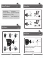
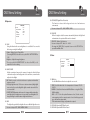
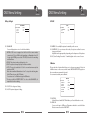
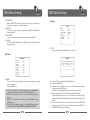
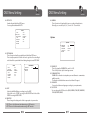
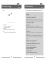
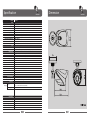
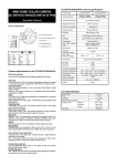
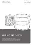
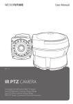
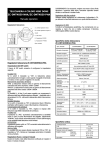
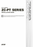
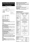
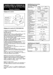
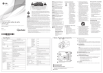
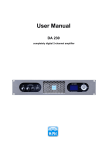
User Manual
Ver. 1.2 [61]
VB-70IR35
Super High Resolution (Color 700 TVL)
3D-DNR, DWDR, AGC, DPC, HLI
Motion Detection : 4 Zone ISO Control / Output OSD
SENS-UP : OFF/ AUTO/ FIXED (Selectable X2 ~ X1024)
Contents
VB-70IR35
CONTENTS ········································································································································ 2
COMPONENTS ································································································································ 2
WARNINGS & CAUTIONS ············································································································
3
GENERAL FEATURES ····················································································································
6
PART NAMES ··································································································································
6
INSTALLATION ·······························································································································
7
OSD MENU SETTING ···················································································································
8
TROUBLE SHOOTING ·················································································································· 19
Warnings & Cautions
VB-70IR35
• If you fail to read this information and handle the product incorrectly, death
or serious injury may occur.
• The unit should be installed by trained personnel.
• Switch off immediately if the product emits smoke or abnormal heat.
• Never install the product in an area with exposed oil or gas.
• Never install the product on a ceiling that cannot hold its weight.
• Never touch the power cord with wet hands. Clean only with dry cloth.
• Never install the product in extreme high or low temperature.
• Never drop, hit strongly or cause the product to vibrate.
• Never expose the product to direct sunlight or severe ray.
SPECIFICATION ····························································································································· 20
DIMENSIONS ································································································································· 21
CAUTION
RISK OF ELECTRIC SHOCK
DO NOT OPEN
Components
DC TYPE [Fixed Lens]
1. Compact IR Bullet Camera
2. Tapping Screw 4 x 30
3 EA
3. Calblock
3 EA
4. L - Wrench
1 EA
5. Manual
VB-70IR35
DC TYPE
1. Compact IR Bullet Camera
2. Tapping Screw 4 x 30
3 EA
3. Calblock
3 EA
4. L - Wrench
1 EA
5. Manual
002
CAUTION: TO REDUCE THE RISK OF ELECTRIC SHOCK,
DO NOT REMOVE COVER (OR BACK)
NO USER SERVICEABLE PARTS INSIDE.
REFER SERVICING TO QUALIFIED SERVICE PERSONNEL.
This symbol is intended to alert the user to the presence
of un-insulated “dangerous voltage” within the product’s
enclosure that may be of sufficient magnitude to
constitute a risk of electric shock to persons.
This symbol is intended to alert the user to the presence
of un-insulated “dangerous voltage” within the product’s
enclosure that may be of sufficient magnitude to
constitute a risk of electric shock to persons.
003
WEEE Compliance statement
VB-70IR35
Français/French
Élimination de votre ancien appareil
1. Ce symbole, représentant une poubelle
sur roulettes barrée d'une croix, signifie
que le produit est couvert par la directive
européenne 2002/96/EC.
2. Tous les produits électriques et
électroniques doivent être éliminés
séparément de la chaîne de collecte
municipale des ordures, par l’ intermédiaire
des installations de collecte prescrites et
désignées par le gouvernement ou les
autorités locales.
3. Une élimination conforme aux instructions
aidera à réduire les conséquences négatives
et risques éventuels pour l'environnement
et la santé humaine.
4. Pour plus d'informations concernant
l'élimination de votre ancien appareil,
veuillez contacter votre mairie, le service des
ordures ménagères ou encore le magasin où
vous avez acheté ce produit.
Deutsch/German
Entsorgung von Altgeräten
English
Disposal of your old appliance
1. When this crossed-out wheeled bin symbol
is attached to a product it means the product
is covered by the European Directive 2002/96/
EC.
2. All electrical and electronic products should
be disposed of separately from the municipal
waste stream via designated collection
facilities appointed by the government or the
local authorities.
3. The correct disposal of your old appliance
will help prevent potential negative
consequences for the environment and
human health.
4. For more detailed information about
disposal of your old appliance, please contact
your city office, waste disposal service or the
shop where you purchased the product.
1. Wenn dieses Symbol eines
durchgestrichenen Abfalleimers auf
einem Produkt angebracht ist, unterliegt
dieses Produkt der europäischen Richtlinie
2002/96/EC.
2. Alle Elektro- und Elektronik-Altgeräte
müssen getrennt vom Hausmüll über
die dafür staatlich vorgesehenen Stellen
entsorgt werden.
3. Mit der ordnungsgemäßen Entsorgung
des alten Geräts vermeiden Sie
Umweltschäden und eine Gefährdung der
persönlichen
Gesundheit.
4. Weitere Informationen zur Entsorgung
des alten Geräts erhalten Sie bei der
Stadtverwaltung, beim Entsorgungsamt
oder in dem Geschäft, wo Sie das Produkt
erworben haben.
004
WEEE Compliance statement
Italiano/Italian
RAEE: SMALTIMENTO DELLE VOSTRE
VECCHIE APPARECCHIATURE
VB-70IR35
odpadów lub sklepem, w którym produkt
został kupiony.
1. Quando il simbolo del “Cassonetto Barrato”
è apposto su un prodotto, significa che lo
stesso può ricadere nei termini previsti dalla
Direttiva Europea nr. 2002/96/EC in funzione
dell’attuazione definita dalla Legislazione dei
singoli stati membri dell’Unione Europea.
2. Tutti i prodotti elettrici ed elettronici
dovrebbero
essere smaltiti separatamente dai rifiuti
municipali, tramite appositi contenitori,
approvati dall’Amministrazione Comunale o
dalle Autorità Locali.
3. Il corretto smaltimento delle vostre vecchie
apparecchiature, contribuirà a prevenire
possibili conseguenze di impatto negativo sull’
ambiente e per la salute dell’uomo.
4. Per maggiori informazioni circa lo
smaltimento
delle vostre vecchie apparecchiature, siete
pregati di contattare l’ufficio municipale della
vostra città, il servizio di smaltimento rifiuti o
il punto vendita nel quale avete acquistato il
prodotto.
Polski/Polish
Utylizacja starych urządzeń
1. Kiedy do produktu dołączony jest niniejszy
przekreślony symbol kołowego pojemnika
na śmieci, oznacza to, że produkt jest objęty
europejską dyrektywą 2002/96/EC.
2. Wszystkie elektryczne i elektroniczne
produkty powinny być utylizowane niezależnie
od odpadów miejskich, z wykorzystaniem
przeznaczonych do tego miejsc składowania
wskazanych przez rząd lub miejscowe władze.
3. Właściwy sposób utylizacji starego
urządzenia
pomoże zapobiec potencjalnie negatywnemu
wpływowi na zdrowie i środowisko.
4. Aby uzyskać więcej informacji o
sposobach utylizacji starych urządzeń, należy
skontaktować się z władzami lokalnymi,
przedsiębiorstwem zajmującym się utylizacją
Português/Portuguese
Eliminação do seu antigo aparelho
1. Quando este símbolo de latão cruzado
estiver afixado a um produto, significa que o
produto é abrangido pela Directiva Europeia
2002/96/EC.
2. Todos os produtos eléctricos e electrónicos
devem ser eliminados separadamente da
coleta de lixo municipal através de pontos de
recolha designados, facilitados pelo governo
ou autoridades locais.
3. A eliminação correcta do seu aparelho
antigo ajuda a evitar potenciais consequências
negativas para o ambiente e para a saúde
humana.
4. Para obter informaçõs mais detalhadas
acerca da eliminação do seu aparelho antigo,
contacte as autoridades locais, um serviço
de eliminação de resíduos ou a loja onde
comprou o produto.
Español/Spanish
Cómo deshacerse de aparatos
eléctricos y electrónicos viejos
1. Si en un producto aparece el símbolo de un
contenedor de basura tachado, significa que
éste se acoge a la Directiva 2002/96/EC.
2. Todos los aparatos eléctricos o electrónicos
se deben desechar de forma distinta del
servicio municipal de recogida de basura, a
través de puntos de recogida designados por
el gobierno o las autoridades locales.
3. La correcta recogida y tratamiento de los
dispositivos inservibles contribuye a evitar
riesgos potenciales para el medio ambiente y
la salud pública.
4. Para obtener más información sobre cómo
deshacerse de sus aparatos eléctricos y
electrónicos viejos, póngase en contacto con
su ayuntamiento, el servicio de recogida de
basuras o el establecimiento donde adquirió
el producto.
005
General Features
VB-70IR35
Connection
VB-70IR35
DC TYPE
• Super High Resolution
• Motion Detection
(Color 700 TVL, B/W : 700TVL)
(4 Zone ISO Control / Output OSD)
• 3D-DNR (3D Digital Noise Reduction)
• SENS-UP
• DWDR / AGC / DPC / HLI
OFF / AUTO / FIXED (Selectable X2 ~ X1024)
Monitor
Video Output
(CVBS)
Adapter
[DC 12V]
DC TYPE
Monitor
Video Output
(CVBS)
DC Jack Plug
Part Names
[DC 12V
Adapter
]
VB-70IR35
IR LED
CAP Screw
1/4” x 9mm
Bracket
(Bottom)
Installation
VB-70IR35
Wall or Ceiling
Sunvisor
Focus & Zoom
(Varifocal)
Mark Positions
3 Axis Bracket
OSD Control
Switch
006
Bracket
(Middle)
1. If you want to install the camera on a concrete wall, you need to make four
8mm diameter holes by drill.(depth 37mm)
2. Install set calblock on the holes.
3. To install Wall or Ceiling bracket.
4. Assemble a Wall or Ceiling mount bracket.
007
OSD Menu Setting
VB-70IR35
OSD Menu Setting
VB-70IR35
A. OSD Menu Table
MAIN MENU
EXPOSURE
COLOR
DAY&NIGHT
FUNC
MOTION
PRIVACY
SETUP
SYSTEM
EXIT
FUNCTION
MIRROR
SHARPNESS
LSC
RETURN
EXPOSURE
LENS
HBLC/D-WDR
AGC
3D DNR
SENSE-UP
RETURN
BLC
BLC MODE
BLC WEIGHT
RETURN
COLOR
WB MODE
R-Y GAIN
B-Y GAIN
RETURN
DAY&NIGHT
D&N MODE
C_SUP
A_SUP
RETURN
MOTION
MOTION
AREA SEL
SENSITI
DISPLAY
HOLD TIME
ALARM
RETURN
CENTER
LEFT
PRIVACY
HLI
D-WDR
D-WDR LEVEL
RETURN
008
RIGHT
SETUP
UP / DOWN BUTTON
• Used to choose the desired menu
selection.
LEFT / RIGHT BUTTON
• Used to choose the desired menu
feature adjustment.
DOWN
MASK1
MASK2
MASK3
MASK4
MASK5
MASK6
MASK7
MASK8
RETURN
HBLC
MODE
SET LEVEL
GRAY MODE
MASK SEL
RETURN
CENTER BUTTON
• Used to access menu mode. Also used
to confirm the menu setting.
UP
EXPOSURE
TITLE
DPC AUTO
DPC MANUAL
OLPF
MONITOR
GAMMA
RETURN
▶LENS
HBLC/D-WDR
AGC
3D DNR
SENSE-UP
RETURN
DC↲
OFF
HIGH
MID
OFF
SYSTEM
CAMERA ID
COMMUNI.
LANGUAGE
OSD COLOR
RETURN
Select the function using Up or Down.
Select to Change the status using Left or Right.
Icon means menu item is unavailable under certain conditions.
009
OSD Menu Setting
VB-70IR35
B. Exposure
EXPOSURE
▶LENS
HBLC/D-WDR
AGC
3D DNR
SENSE-UP
RETURN
DC↲
OFF
HIGH
MID
OFF
B-1. LENS
Using this function the screen brightness is controllable. You can select
the lens type using Left and Right.
• Shutter : Shutter Speed is Controllable.
(On using INDOOR, it should be set up the LENS SHUTTER SPEED as
1/60)
• Brightness : Adjust the image brightness.
* It's not possible for FACROTY RESET to choose the LENS, so it's
required to check on setting.
B-2 . HBLC/D-WDR
Unlike conventional cameras, the camera is designed so that it delivers
a distinctive subject and background at the same time, even when the
subject is in backlight.
• BLC : Enables a user to select a desired area on a picture and view that
area more clearly.
• HLI (High Light Inversion) : If the scene contains extremely bright light
areas such as; from car headlight the light can mask out much of the
on-screen detail.
• D-WDR : DWDR illuminates darker areas of an image while retaining the
same light level for brighter areas to even out the overall brightness of
images with high contrast between bright and dark areas.
B-3. AGC
The higher the gain level, the brighter the screen. But the higher the noise.
• You can set it up as OFF / LOW / MIDDLE / HIGH.
010
OSD Menu Setting
VB-70IR35
B-4. 3D-DNR (3D Digital Noise Reduction)
This function reduces the background noise in a low luminance
environment.
• You can set it up as OFF / LOW / MIDDLE / HIGH.
B-5. SENSE UP
When it is night or dark, the camera automatically detects the light level
and maintains a clear picture if this mode is activated.
• SENSE UP : Shutter Scale Function.
• You can set it up as OFF / Auto / x2 ~ x1024.
• On using the SENSE UP, it's required to turn on the DPC AUTO to
prevent from White Pixel.
C. Color
COLOR
▶WB MODE
R-Y GAIN
B-Y GAIN
RETURN
ATW
128
128
C-1. WB Mode
Use the White Balance function to adjust the screen color.
• ATW: Select this when the color temperature is between 2700°K ~
9500°K.
• MANUAL : Select this to fine-tune the White Balance - using the ATW or
AWC mode first.
• AWC -> SET : To fine the optimal luminance level, for the current
environment, point the camera toward a sheet of white paper and
press the function setup switch.
If the environment changes, readjustment is required.
C-2. R-Y GAIN : Adjust the RED Gain Control.
C-3. B-Y GAIN : Adjust the BLUE Gain Control.
011
OSD Menu Setting
VB-70IR35
D. Day & Nignt
OSD Menu Setting
VB-70IR35
E. FUNC
DAY&NIGHT
▶D&N MODE
C_SUP
A_SUP
RETURN
FUNC
EXT.↵
020
020
D-1. D&N MODE
You can display pictures in color or black and white.
• EXTERN : CDS sensor equipped on the front of the camera makes
conversion to Color or B/W mode depending on illumination level. If
Set into the EXTERN, pressed the SET KEY, it'd feasible for switching
and Dwell time.
• COLOR : The picture is always displayed in color.
• B/W : The picture is always displayed in black and white.
• AUTO : The mode is switched to ‘Color’ in a normal environment, but
switches to ‘BW’.
Mode when ambient illumination is low. To set up the switching time
for AUTO mode, press the SET button.
You can turn on or off the burst signal in B/W mode.
* It's not possible for FACROTY RESET to choose the D&N MODE, it's
required to check on setting.
D-2. C-SUP : Color Suppress Setting.
D-3. A-SUP : Aperture Suppress Setting.
▶MIRROR
SHARPNESS
LSC
RETURN
OFF
010
OFF
E-1. MIRROR : You can flip the picture horizontally on the screen.
E-2. SHARPNESS : As you increase this value, the picture outline becomes
stronger and clearer.
Adjust this value appropriately depending on the sharpness of the picture.
E-3. LSC (Lens Shading Correction) : To make brighter on the corner of screen.
F. Motion
This product has a feature that allows you to observe movement of object in
4 different areas on the screen, and the words ‘MOTION DETECTED’ appear on
the screen when movement is detected.
You can monitor activity more efficient.
MOTION
▶MOTION
AREA SEL
SENSITI.
DISPLAY
HOLD TIME
ALARM
RETURN
ON
AREA1
002
TRACE
003
OFF
F-1. MOTION
It should be used with ON / OFF whether you'd use this function or not.
F-2. AREA SEL
You can select up to 4 MD areas. Determines whether to use the Motion
Detection area selected in SENSITIVITY.
012
013
OSD Menu Setting
VB-70IR35
F-3. SENSITIVITY
When SENSITIVITY number is high, motion detection sensitivity is
increased to recognize even small movement.
F-4. DISPLAY
You can choose the way of setting between ICON and TRACE when
detection the MD.
F-5. HOLD TIME
You can set up the time of alarm output when detection the MD.
F-6. ALARM
This is for ON / OFF of alarm. (In case of this product, It's not feasible to use
the alarm output.)
OSD Menu Setting
VB-70IR35
H. Setup
SETUP
▶TITLE
DPC AUTO
DPC MANUAL
OLPF
MONITOR
GAMMA
RETURN
ON↵
AUTO↵
MANUAL↵
FILTER2
CRT
0.45
H-1. TITLE
If you enter a title, the title will appear on the monitor.
G. Privacy
DAY&NIGHT
MASK1
ON↵
MASK2
ON↵
MASK3ON↵
MASK4
ON↵
MASK5
ON↵
MASK6
ON↵
MASK7
ON↵
MASK8
ON↵
RETURN
G-1. MASK
Privacy is a privacy protection function that makes certain areas set by
user to be masked.
Selectable Mask 1 ~ 8.
USER TITLE
ABCDEFGHIJKLMNO
QRSTUVWXYZ01234
6 7 8 9 ! " # $ % & ' ( ) *
, - . / : ; < = > ? @ [ \ ] ^
←
→
CLR
POS
P
5
+
_
RET
______________________
• DOT SEL : It is the function to decide the DOT position controlling size
of the MASK and it can be set with L_TOP, R_TOP, L BOT, R_BOT.
• DOT XY : It's the function to set the size of the MASK moving DOT
choosen.
• MOVE XY : It's the function to set the position of the MASK moving
MASK choosen.
• COLOR SET : It's the function to set the color of the MASK and it can be
set with BLACK, WHITE, RED, GREEN, BLUE, MAGENTA, CYAN,GRAY.
H-1-2. Set in to ‘ON’ by using the Left and Right buttons.
H-1-3. Press the SET button.
H-1-4. Use the 4 direction buttons to move to a desired letter and select the
letter by pressing the SET button.
Repeat this to enter multiple letters. You can enter up to 15 letters.
H-1-5. Enter a title, move the cursor to ‘POS’ and press the SET button.
The entered title appears on the screen. Select the position to display
the title on the screen by using the 4 direction buttons and press the SET
button.
H-1-6. Press the 'RET' if position is decided and then press the SAVE & EXIT
going back to menu. (Once you have determined the location 'RET', click
the SAVE & EXIT to return to the menu.)
014
015
OSD Menu Setting
VB-70IR35
H-2. DPC AUTO
It masks the pixel died from CCD sensor.
You can get it vitalized with 'AUTO'.
OSD Menu Setting
VB-70IR35
H-6. GAMMA
This is for revision of signal which is error according to display device.
Basically, you can set it up 0.45, 0.6, 1.0 and 0.20~1.0 user inside.
SETUP
TITLE
▶DPC AUTO
DPC MANUAL
OLPF
MONITOR
GAMMA
RETURN
ON↵
AUTO↵
MANUAL↵
FILTER2
CRT
0.45
I. System
SYSTEM
H-3. DPC MANUAL
This is for revision handle-operated the pixel died from CCD sensor.
This is totally required to block the lens not to get in before controlling it
and it should be operated with Level setting about get started 'DPC RUN'.
SETUP
TITLE
DPC AUTO
▶DPC MANUAL
OLPF
MONITOR
GAMMA
RETURN
DPC-MANUAL
ON↵
AUTO↵
MANUAL↵
FILTER2
CRT
0.45
DPC LEVEL
▶DPC RUN
RETURN
20
H-4. OLPF
It decides the White Balance according to use the OLPF.
It should be set to FILTER1 on using the BLUE FILTER and it should be
FILTER2 on using the RED FILTER.
H-5. MONITOR
Please change the settings value of video appropriate to your monitor.
▶CAMERA ID
COMMUNI.
LANGUAGE
OSD COLOR
RETURN
001
OFF
ENGLISH
BLUE
I-1. CAMERA ID
This is for set up the CAMERA ID. It can be 1 to 255.
This is for IP product only. Not analogue camera.
I-2. COMMUNICATION
COMM ADJ is a function to setup when you want Camera to communicate
with the outside.
The function is disabled when camera doesn’t have IP support.
I-3. LANGUAGE
You can select the menu language according to your requirements.
I-4. OSD COLOR
You can change the OSD front color. (BULE, GREEN, CYAN, RED, MAGENTA,
YELLOW, PURPLE, GRAY)
• LCD : Please select this menu item when using on LCD monitor.
• CRT : Please select this menu item when using a CRT monitor.
016
017
OSD Menu Setting
VB-70IR35
J. Exit
Trouble Shooting
VB-70IR35
If you have trouble setting up or operating the camera, refer to the following.
EXIT
▶FACTORY SET
SAVE&EXIT
EXIT
NO
NO PICTURE
• Check if the Power is connected correctly.
• Check if all the cable is connected correctly.
CAMERA WITH HEAT, ABNORMAL MOTION BLACK LINES ON THE SCREEN.
• Check if the power supply meets standard requirements and if the
power supply changes irregularly.
J-1. FACTORY SET
It can get camera setting initialized.
Except for LENS, D&N MODE .
J-2. SAVE & EXIT
It can be finished after saving the camera setting.
J-3. EXIT
It can be finished after not saving the camera setting.
BLINKING SCREEN
• Check if the camera set toward sun or fluorescent lamp.
• Check if the connector of Auto Iris Lens is connected correctly when
using.
UNCLEAR SCREEN
• Check if the lens gets dirty. (You can wipe out with clean fabric or
brush.)
• Check if the monitor is in a condition as following. (If light is coming
inside too much, you can change the angel if camera or adjust backfocus.)
NO OPERATION OF COLOR MODE OR B/W MODE
• Check the camera is set to ‘DAY NIGHT’ mode.
• Check the Level value of DAY&NIGHT Mode to be corrected.
NO OPERATION OF MOTION DETECTION
• Check if you set ‘Motion Detection’ mode off.
• Check if you set ‘Area’ properly.
WRONG COLOR DISPLAY
• Check if you set ‘White Balance’ mode correctly.
018
019
Specification
MODEL
VIDEO
Image Sensor
Total Pixels
Effective Pixels
Scanning System
Scanning Frequency
Synchronization
Shutter Speed
Horizontal Resolution
S/N Ratio
Min. Illumination
Video Output
LENS
Lens
Angular Field Of View
OPERATIONAL
On Screen Display
Day & Night
Motion Detection
Privacy Masking
White Balance
DNR
WDR
Sens-Up
Auto Gain Control
DPC
Sharpness
Heater
ENVIRONMENTAL
Operating Temp. / Stroge Temp.
Operation humidity
ELECTRICAL
DC Type
Power
Power Supply
MECHANICAL
Dimensions
Weight
IR LED
Ingress Protection
Certifications
Outside Control
VB-70IR35
Dimension
VB-70IR35
VB-70IR35
1/3" Sony Super HAD II CCD
NTSC : 811(H) x 508(V), PAL : 795(H) x 596(V)
NTSC : 768(H) x 494(V), PAL : 752(H) x 582(V)
2:1 Interlace
NTSC : 15.734kHz x 59.94Hz, PAL : 15.625kHz x 50Hz
Internal
NTSC : 1/60s ~ 1/100,000s, PAL : 1/50s ~ 1/100,000s
Max 700TVL
50dB or more (AGC Off )
Color : 0.1Lux, B/W : 0.01Lux, Sens up : 0.0001 Lux (F1.2 at 30 IRE)
VBS 1.0V p-p / 75Ω
3.6mm, 4.3mm, 6.0mm
[3.6mm] H : 72° V:53° , [4.3mm] H : 63.7° V:52.1°, [6.0mm] H : 46° V:34°
Support
COLOR / BW / AUTO / EXT. Selectable
On / Off (4 Zone ISO Control/ Output OSD)
On / Off (8 Areas)
ATW1, ATW2/AWC->SET/MANUAL
3D-DNR : OFF / AUTO / LOW / MIDDLE / HIGH
DWDR
OFF / AUTO / FIXED (Selectable X2 ~ X1024)
OFF / LOW / MIDDLE / HIGH Selectable
AUTO / MANUAL / OFF
Level Adjustable
Option
-10°C ~ +50°C (With Heater : -40°C ~ +50°C) / -20°C ~ +60°C
Under 90% (Non-condensing)
Fixed Lens : MAX. DC12V 400mA [4.8W])
DC12V 500mA
124mm(W) x 80.8mm(H) x 83.5mm(D)
450g
IP68
CE, FCC
OSD
020
021
Memo
VB-70IR35
022
Memo
VB-70IR35
023
VB-70IR35
Ver. 1.2 [61]