1
United States Patent [191
[11]
4,204,208
McCarthy
[45]
May 20, 1980
[S4] DISPLAY OF VIDEO IMAGE?
[75] Inventor: Edward C. McCarthy, Indian Harbor
Beach, Fla.
such as a font, of related images to be displayed. A
second coded data character is provided which repre
sents a second graphical image from a second library,
such as a font, of related images wherein the first library
[73] Assignee: Harris Corporation, Cleveland, Ohio
[21] App]. No.: 829,044
[22] Filed:
Aug. 30, 1977
of related images is independent of the second library of
related images. A storage facility is provided for each
library with the facility storing video display instruc
[51]
Int. Cl.2 ........................................... .. 606K 15/20
[52]
US. Cl. .................................. .. 340/745; 340/751;
the library of graphical images. The storage facility for
the first library of images is interrogated by the ?rst
340/799; 364/900
coded data character to obtain therefrom the video
[58]
Field of Search .............. .. 340/324 AD, 745, 751,
display instructions for forming the image represented
bythat data character. Thestorage facility of images for‘
340/799
[56]
the second library of images is interrogated by the sec
References Cited
U.S. PATENT DOCUMENTS
ond coded data character to obtain from the storage
3,444,319
5/1969
3,624,632
ll/l97l
Ophir . . . . . . . .
3,668,687
6/1972
Hale ........ ..
340/324 AD
3,696,387
l0/ I972
Nussbaum
340/324 AD
3,82l,730
3,883,728
6/1974
5/1975
Artzt et a]. ................. .. 340/324 AD
. . . . . ..
340/799 X
Carey :1 a]. .... ..
340/324 AD
Schwartz et al. ............. .. 340/751 X
Primary Examiner-David L. Trafton
[57]
tions for forming each character or graphical image in
ABSI‘RACI'
The system displays video images of data characters or
facility the video display instructions for forming the
graphical image represented by that data character. The
video display instructions for forming the video image
of the character from the first library are combined with
the instructions for forming the graphical image from
the second library. The combined video display instruc
tions are employed for forming a graphical image hav
ing the combined video characteristics of the images
represented by the ?rst coded data character and the
second coded character.
other graphics with video modifications being made
thereto. A coded data character is provided which
represents a first graphical image from a ?rst library,
12 Claims, 32 Drawing Figures
VIDEO I |//
VIDEO 2
U.S. Patent
May 20, 1980
Sheet 3 of 16
4,204,208
Q\
NM8Q?m?Tv~mNO?
\.
\
\
\
\\
MOE
kw‘
“NW
“WNW
“mm
MM“.“HM
kNW“
3x3.“NW
/
,\
9.
kinQNW
U.S. Patent
May 20, 1980
Sheet 4 of 16
4,204,208
US. Patent
May 20, 1980
Sheet 5 of 16
mu lus
|
AUDI as nus
4,204,208
l
[05
'1
r‘ AB
C0672
nus
_
as
@
swncu Mo
0
n
C
5
MASTER
CLEAR
p
E
qZ
l
l
I
Funk»
7
!
PRIME;
“Hm
T‘ x
l
FEM-nu‘
"'
4295-!
J I
u 4
| §:
1:‘
‘n a i
|
|
I
, ,
our
10'‘,
l
g 3
'i
Q
i "a ‘3°‘xu:"c°'4|":
{2' 1”
I
’
“W52
C
°‘"
seamm
urinm:
Tom
UART
I
I
g 1
%
Anniss aus '
F IG.6
U.S. Patent
May 20, 1980
Sheet 8 of 16
i_.
TIM/N6 GBVEMTOR -———--—l
ACLSY/V
4,204,208
PWRuPs
250
326
dB
CLOCK
da
BLANK
RC
BL/NKC
VIJYNC
STRK 0/
L we 32
l/WC URS
RD E UFA
DB
45
320
lAdd
60 ‘a,‘5 _l_____’
Mrcuks
AB
FIG. l7
US. Patent
May 20, 1980
Sheet 10 of 16
4,204,208
2.0K
U.S. Patent
May 20, 1980
Sheet 11 of 16
4,204,208
QUE
US. Patent
May 20, 1980
Sheet 12 of 16
4,204,208
U.S. Patent
May 20, 1980
Sheet 13 of 16
4,204,208
lmR -
CHMCER
I
5
F | G. 20
W
FIGZla
FlGZlb
F|G2|c
FIGZZQ
FIGZZb
FIGZZc
F|G23a
H6235
F1623c
U.S. Patent
May 20, 1980
Sheet 14 of 16
4,204,208
mn w
U.S. Patent
1
§H|3_%
May 20, 1980
Sheet 15 of 16
4,204,208
U.S. Patent
HMWHHHHE§HQH§
May 20, 1980
Sheet 16 of 16
4,204,208
1
4,204,208
2
tics of a data character from one library or set of data
DISPLAY OF VIDEO IMAGES
BACKGROUND AND FIELD OF THE
INVENTION
This invention relates to the art of video display of
images representing data characters or symbols or other
characters such as the English alphabet, with the visual
characteristics of other data characters or graphical
images from an independent, nonrelated library or set of
graphical images. For example, an editor may want to
graphical images.
change the meaning of the letter “0" taken from the
English alphabet. If a horizontal bar could be placed
through the letter “0", then the meaning of the letter
The invention is particularly applicable for use in
conjunction with a video display system employed in
the Greek alphabet.
text editing and the like and will be described in con
junction therewith; although, it is to be appreciated that
“0" has been changed to theta, a character taken from
Thus it would be desirable to provide a plurality of
storage libraries each storing video instructions for
forming a set of symbols or data characters or other
the invention has broader applications as it may be used
graphics and the like such that when a particular sym
in various video displays wherein it is desired to modify
15 bol or character or graphics is called for, its video image
one video image with another.
may be combined with the video image taken from a
Video display systems having the capability of dis
playing data characters and for modifying video char
acteristics of such data characters are known in the art.
Examples of prior art patents on the subject include the
U.S. Pat. to R. C. Williams Nos. 3,895,374, 3,895,375,
and 3,896,428. These patents each teach video modi?ca
tion of the display of a data character such as inversion
in appearance, intensi?cation, and underlining. One or
different library to form a graphical image having the
combined video characteristics of the various symbols,
characters, or graphics taken from the various libraries.
SUMMARY OF THE INVENTION
It is therefore, a primary object of the present inven
tion to display video image of one type of graphics
more of these modi?cations may be made to a data
(such as a data character) in combination with the video
character. The apparatus disclosed in those patents by 25 image of a another type of graphics (such as a symbol)
employs a data stream wherein the data characters are
encoded in binary form and are preceded by a binary
encoded attribute character which commands the attri
bute or modi?cation to be made to the data characters
so as to obtain an image having the combined video
characteristics thereof.
It is a still further object of the present invention to
provide improvements in modifying the video appear
following the attribute character. The attribute charac 30 ance of the image of a data character without requiring
ter is a multi-bit character with each bit being represen
tative of one of several attribute modi?cations which
may be made.
A notable problem with such display systems as de
scribed above is that logic circuitry must be employed
to decode each multi-bit attribute character to decide
which modi?cation or modi?cations are to be made to
complex logic circuitry.
It is a still further object of the present invention to
provide improvements in modifying the video appear
ance of the image of a data character so as to change its
meaning.
It is a still further object of the present invention to
provide improvements in modifying the video appear
the visual images representing the data characters fol
ance of images representing data characters wherein
lowing the attribute character. The video image of each
such
modi?cations include cross hatch, strike-through,
data character is formed by obtaining video instructions 40
for that character from a look-up table, such as a read
only memory. These instructions are supplied to a video
generator which may include a TV. raster scan for
underline, italic and dotted underline and these are
obtained from a storage library means containing the
intensi?cation or inversion in appearance since each dot
that a user may devise his own sets of graphics to obtain
position is enhanced in the same fashion. Consequently,
his own combinations of graphical images and the like.
In accordance with one aspect of the present inven
video display instructions for forming each of these
enhancements and that these instructions be combined
forming segmental dot patterns or dot slices of each of
a plurality of characters forming a character line. Sev 45 with data character image forming instructions ob
tained from a similar storage library for forming the
eral scans are made until each character of the character
image of the data character with one or more of these
line has been formed. Logic circuitry must be employed
enhancements.
to respond to the attribute data character to make the
It is a still futher object of the present invention that
appropriate video modi?cations to the images‘of the
the storage facilities for the sets of data characters or
data characters being formed. The complexity of such
symbols or other graphics be ?eld programmable so
logic circuitry is at one level with such enhancements as
only one piece of information is required by the logic
circuitry. The logic circuitry required ‘becomes far
more complex for such attributes or enhancements as
tion, the video display system displays video images of
data characters or other graphics with video modi?ca
tions being made thereto. A coded data character is
strike-through, underlining, or cross hatch because each
provided which represents a ?rst graphical image from
of these require that the dot pattern of the enhancement
a ?rst library, such as a font, of related images to be
be combined with the dot pattern representing the vi
sual image of the data character. Moreover, such com 60 displayed. A second coded data character is provided
which represents a second graphical image from a sec
plex logic circuitry to provide these attributes or en
ond library, such as a font, of related images wherein
hancement would not be programmable in the ?eld.
the ?rst library of related images is independent of the
Consequently, the user of such equipment would be
second library of related images. A storage facility is
limited to those attributes or enhancements provided by
the terminal manufacturer.
65 provided for each library with the facility storing video
display instructions for forming each character or
Another disadvantage of such video display terminals
as that discussed above is the inability to easily create
graphical image in the library of graphical images. The
graphical images which combine the visual characteris
storage facility for the ?rst library of images is interro~
3
4,204,208
4
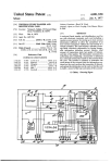
FIG. 17 is a schematic-block diagram illustration of
gated by the ?rst coded data character to obtain there
from the video display instructions for forming the
the cursor logic circuitry illustrated in FIG. 14;
image represented by that data character. The storage
facility of images for the second library of graphical
images is interrogated by the second coded data charac
ter to obtain from the storage facility the video display
instructions for forming the graphical image repre
sented by that data character. The video display instruc
tions for forming the video image of the character from
FIGS. 18a through 18f are waveforms useful in de
scribing both single and dual column operation;
FIGS. 19a through 19p are waveforms useful in de
scribing portions of the circuitry employed herein;
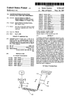
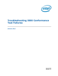
FIG. 20 is a schematic illustration of a pixel matrix;
FIGS. 21a. b, and c are graphical illustrations show
ing images formed on the video display;
the ?rst library are combined with the instructions for 0
forming the graphical image from the second library.
The combined video display instructions are employed
for forming a graphical image having the combined
video characteristics of the images represented by the
?rst coded data character and the second coded charac
FIGS. 220, b. and c are similar to that of FIGS. 210,
b and c but showing a different combination of graphi
cal images formed on the video display;
FIGS. 23a. b, and c are similar to those of FIGS. 21a,
b, c and 22a, b. and 0 but showing a different combina
tion of graphical images formed on the video display;
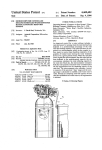
FIG. 24 is a schematic-block diagram illustration of
the direct memory access circuitry;
FIGS. 250 through 25m are waveforms useful in
ter.
In accordance with a more limited aspect of the pres
ent invention, one of the storage facilities referred to
describing the circuitry of FIG. 24; and,
above is used for storing video display instructions for
forming each data character taken from a font of data 20 FIGS. 260 through 26p are waveforms useful in de
scribing the circuitry of FIG. 24.
characters and another storage facility is used for stor
ing video display instructions for each of a plurality of
DETAILED DESCRIPTION
enhancement characters such as cross hatch, strike
General Description
through, underline, italic and dotted underline.
BRIEF DESCRIPTION OF THE DRAWINGS
The foregoing and other objects and advantages of
the invention will become more readily apparent from
the following description of the preferred embodiment
of the invention as taken in conjunction with the ap
pended drawings wherein:
FIG. 1 is an overall system block diagram illustrating
for an application of the present invention;
FIG. 2 is a schematic-block diagram illustration of a
video display terminal in accordance with the present
invention;
FIG. 3 is a schematic illustration of the keyboard
layout for the keyboard of the terminal illustrated in
FIG. 2;
FIG. 4 is a schematic-block diagram illustration of
the CPU and interface circuitry;
FIG. 5 is a schematic-block diagram illustration of
25
Reference is now made to the drawings wherein the
showings are for purposes of illustrating a preferred
embodiment of the invention only and not for purposes
of limiting same.
FIG. 1 is a generalized block diagram illustrating a
system to which the present invention applies. Here
there is illustrated a host computer I-IC which, for ex
ample, may take the form of a PDP-ll/35 computer
with 64K words of memory obtained from Digital
Equipment Corporation. Associated with the host com
puter is a large data base storage DB8 and which may
take the form of disc ?les, such as two 2.4 million byte
moving head discs. The system disclosed in FIG. 1 also
includes data input sources DIS which may include, for
example, wire lines from which UPI and AP stories are
40 obtained. Other input sources may include a paper tape
source or an optical (OCR) reader or a modem.
These data input sources provide stories and the like
which may be inputted under the control of the host
computer BC by way a system multiplexer MX for
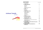
FIG. 6 is a schematic-block diagram illustration of
the memory and its interface with the common bus 45 storage in the appropriate ?le at the data base storage
DBS. Also associated with the system is a plurality of
structure;
the input/output control circuitry;
FIG. 7 is a schematic illustration of the display screen
editing terminals T1, T2, through TN. Each editing
of the terminal illustrated in FIG. 2;
terminal takes the form of a processor driven video
FIG. 8 is a schematic illustration of the line vector
table in the main memory;
FIG. 9 is a schematic illustration showing the manner
in which bytes of data are stored in a display buffer in a
display terminal having a keyboard and a display
single column mode;
screen. With such a system, a news writer may use an
editing terminal to create a story which is displayed on
the display screen. Once the writer is satis?ed with the
story, he will actuate a send key and coded data repre
sentative of the story will be supplied through the sys
FIG. 10 is similar to that of FIG. 9 but showing the
55 tem multiplexer MX to the host computer I-IC which
display buffer in the dual or split screen mode;
will then store the story in a particular storage location
FIG. 11 is a schematic illustration showing the man
at the data base storage DB8 for subsequent retrieval.
ner in which enhancement data and character data are
Other stories may be obtained from the data input
arranged for a character line;
sources DIS and routed by host computer HC for stor
FIG. 12 is a schematic illustration showing the format
age in the data base storage DBS.
of a data word;
FIG. 13 is a schematic illustration showing the format
An editor, through the use of his editing terminal,
of an enhancement;
FIG. 14 is a schematic-block diagram illustration of
the timing generator circuitry;
may call up a story entered into the data base storage
from either one of his writers or from one of the data
input sources DIS. In this case, the proper keys on the
FIG. 15 is a schematic-block diagram illustration of 65 terminal’s keyboard will be actuated and the story will
be retrieved from the data base storage and supplied
under the control of the host computer BC to the termi
FIGS. 160 through 161' are waveforms useful in un
nal requesting the story. The editor will now view the
derstanding portions of the circuitry described herein;
the video generator circuitry;
4,204,208
story on his display screen and make whatever editing
6
storage in the main memory M. The terminal is now
corrections he requires, using the proper editing con
programmed to perform its intended operation, i.e.,
trols on the keyboard. Once the edited story has been
completed, the editor will actuate a send key on the
keyboard and the edited story will now be stored at the
data base storage but in a different location from the
unedited story. An edited story located at the data base
storage will, under computer control, be supplied to one
or more of a plurality of data output devices DOD.
Suitable output devices known in the art include type
such as a sports editor terminal. In such case, the editor
setters, papertape punches, printers and modems. Sys
tems of the nature described thus far are well known in
the art and have been installed in several newspaper
facilities. No further description of the overall system
will be presented herein unless it has particular concern
with respect to the invention.
Video Display Terminal (General)
Reference is now made to‘FIG. 2 which illustrates a
will now employ the keyboard KB for transmitting a
code to the host computer to ask for a particular story.
Under the program control, the information provided
by the keyboard KB will appear on the data bus line and
then be transmitted by way of the input output control
[0 to the host computer. The host computer will then
retrieve the requested story from the data base storage
DES and supply the story to the terminal. Under pro
gram control, the terminal will route the story for stor
age in the main memory M. At this point, the main
memory M will store both program instructions for
internal operation of the processor as well as the data
representing the text to be displayed on the CRT.
The data characters stored in main memory are read
and routed to the character generator where the data
characters are decoded to obtain the proper video dot
block diagram of a video display terminal in accordance 20 pattern for display on the CRT screen. The main mem
with the present invention and which may be used in a
system such as that illustrated in FIG. 1. The terminal T
of FIG. 2 is a processor-driven terminal employing a
ory is accessed under the control of a direct memory
access control circuit DMA. This circuit operates in
response to control signals from the character generator
CG and fetches data from the memory with the data
common bus structure. The bus structure may be di
vided into an address bus AB, a data bus DB and a 25 then being supplied to the character generator by way
control bus CB. By way of example only, the address
of a data bus DB. The data received by the character
bus may be a 16 bit bus and the data bus may be an 8 bit
generator is then employed to provide video patterns
representative of data characters for display on the
bus. An interface to the host computer HC is obtained
with an input/output control [0. The input/output
control [0, in a conventional manner, communicates
with the address bus, the data bus and the control bus.
Also connected to the common bus is the central pro
cessing unit CPU, a bootstrap memory BS, a main ran
dom access memory M, a keyboard KB, and a video
cathode ray tube CRT.
Before explaining the various circuits in detail, the
following discussion is presented with respect to vari
ous blocks illustrated in FIG. 2. For example, the pro
cessor CPU serves to execute programs which are
downloaded to the main memory M. The processor
display control VDC which includes a direct memory 35 may take any convenient form of microprocessor such
as the Intel Microprocessor Model 8080 and which is
access circuit DMA and a character generator CG.
described in detail in that company's User's Manual
The character generator communicates in a conven—
98-l53C dated September, 1975. The reader is refer
tional fashion with a display means in the form of a
enced to that manual for a complete discussion of the
cathode ray tube CRT by way of a suitable video ampli
?er VA and vertical and horizontal de?ection amplify 40 processor. Basically, it takes the form of an 8 bit ma
ing circuitry DA. A power supply circuit PS is acti
chine having an 8 bit directional data bus, a 16 bit ad
vated upon closure of a switch SW to receive A.C. line
dress bus, and has addressing capability for up to 6441!]
8 bit bytes of memory.
power. The power supply provides the various DC
level signals required ‘by the circuitry as well as an
The bootstrap memory BS includes a programmable
output which carries an AC line signal to a power line 45 read only memory (PROM). This is a non-volatile stor
synchronization generator PLS. For example, the AC
line signal may be a six volt RMS signal. The power line
age of a bootstrap program which, when executed by
the CPU during the power-up sequence of the terminal,
synchronization generator PLS provides output pulses
causes transmission of a message by way of the data bus
that are synchronized to the AC line signal. as shown by
DB to the host computer HC requesting a download of
the terminal control program. The downloaded pro
gram is stored in the terminal's main memory M which
includes storage capacity for the text data to be dis
the waveforms in FIG. 2, and this provides output
pulses to the character generator to provide a command
for start of frame (STRTFR). A control“ output is also
obtained from the power supply circuit PS to provide a
played on the CRT as well as working memory for use
power-up signal (PWRURS).
by the CPU. The main memory M may take the form of
A general description of the operation of the terminal
a [6K 8 bit word random access memory.
The character generator converts the received data
into a serial video stream which is applied by the video
ampli?er VA to control the blank/unblank operation of
the CRT. A full screen of display may include, for
example, 27 lines of 72 characters each. Preferably, a
interrogation of the bootstrap memory BS which then
TV. raster scan technique is employed and which in
supplies to the data bus DB some data in the form of a
corporates a vertical raster. The character generator
terminal identi?cation. The bootstrap memory is a pro
provides to the video ampli?er a serial bit stream which
grammable read only memory or other non-volatile
corresponds to vertical display raster columns. As will
storage facility. The terminal identi?cation is supplied 65 be brought out in greater detail hereinafter, each char
by the data bus DB to the host computer BC by way of
acter is displayed within a 12x15 dot matrix. The dot
the input/output control 10. The‘host computer will
matrix hereinafter will be referred to in terms of pixels
is now presented. As the editor or writer commences
use of the terminal he will actuate a power-on switch
SW which will raise the power-up line PRWUPS. This
is routed to the control bus and from there to the pro
cessor CPU. This causes, under program control, an 60
now download program instructions to the terminal for
(picture elements). The normal character is ll pixels