1
USO057O3347A
United States Patent [191
[11]
[45]
Reddersen et a1.
[54] MULTIPLE-INTERFACE SELECTION
Patent Number:
Date of Patent:
4,889,497
SYSTEM FOR COMPUTER PERIPHERALS
‘
5,703,347
*Dec. 30, 1997
12/1989 Riches ................................... .. 439/620
4,902,244
211990 Endo et a1.
4,915,639
4/1990 Cohn etal. ..... ..
.. 439/433
[75] Inventors: Brad R. Reddersen; Phillip W.
Shepard; Rockie D. Moch; Jon Paul
Charles Williams. all of Eugene, Oreg.
4,941,345
7/1990 Eppley et a1.
.. 4391505
[73] Assignec: Spectra-Physics Scanning Systems,
Inc.. Eugene. Oreg.
The term of this patent shall not extend
5,330,370
5,250,792 10/1993
7/1994 Reddersen
Swartz et a1.
et a1.
[* ] Notice:
beyond the expiration date of Pat. No.
.. 439/488
4,954,101
9/1990 Nelson ........ ..
5,040,993
3/1991 Kr'ug a a1.
.. 439/502
5,092,793
3/1992 Stephan
5,181,858
1/1993 Matz 61 al.
439/439
5,214,268
5/1993 Doing .......... ..
235/462
5,222,164
6/1993 Bass, Sr. 6131. .
438/488
.... .. 439/620
235/472 x
5,563,402
5,347,113 10/1996
9/1994 Reddersen et a].
a1.
5.347.113.
.... ..
235/436
Primary Examiner-Donald T. Hajec
[21] Appl. No.: 706,736
[22] Filed:
Sep. 9, 1996
Assistant Examiner—Karl D. Frech
Attorney, Agent, or Firm-Lyon & Lyon LLP
[57]
Related US. Application Data
ABSTRACT
An interface selection and con?guration system for a com
[63]
Continuation of Ser. No. 305,517, Sep. 13, 1994, Pat. No.
5,563,402, which is a continuation-in-part of Ser. No.
39,606, Mar. 25, 1993, Pat No. 5,347,113, which is a
puter peripheral in which con?guration for the peripheral
No. 5,330,370, which is a continuation of Ser. No. 788,267,
and/or the host interface is at least in part accomplished by
the interface connector cable. In a preferred embodiment,
the computer peripheral is equipped with one or more
Nov. 4, 1991, abandoned.
hardware interfaces. The interface connector cable has a ?rst
continuation-impart of Ser. No. 34,189, Mar. 22, 1996, Pat.
[51]
Int. (:1.6 ..................................................... .. 606K 7110
[52]
[58]
US. Cl.
. 235/472; 235/462
Field of Search ................................ .. 235/462, 472,
235/436; 439/329. 488. 489. 491. 620.
502
[56]
References Cited
4/1986 Shimada ................................ .. 439/620
4,678,288 7/1987 Lonsdale et a1.
4,694,182 9/1987 Howard
4,699,447 10/1987 Howard
cally a multiple pin connector constructed and arranged to
be properly physically and electrically connectable only to a
speci?c computer peripheral or class of computer
peripherals, the ?rst end connector including at least one
electrical connection between two pins for completing a
circuit within the computer peripheral thereby enabling the
computer peripheral. Where the peripheral is a data reading
U.S. PATENT DOCUMENTS
4,579,407
end connector for attaching to the computer peripheral. The
?rst end connector of the interface connector cable is typi
device such as a laser scanner or RFID reader. alternate or
additional con?guration may be obtained, with data reading
350/432
250/566
350/69
which may for example be a bar code or RFID tag. contains
device, from the label on the interconnect cable. The label,
4,820,193
4/1989 Noorily ...... ..
439/488
information or instructions by which the data reading device
4,861,972
4,866,257
8/1989 Elliottet a1. ..
9/1989 Elliott et al. ..
235/462
235/436
(and/or the host) is con?gured.
4,868,375
9/1989 Blanford ............................... .. 235/462
30 Claims, 5 Drawing Sheets
US. Patent
Dec. 30, 1997
COMPUTER
Sheet 1 of 5
5,703,347
US. Patent
Dec. 30, 1997
Sheet 2 of 5
5,703,347
[12.3
42
\ICDU'-PAN
US. Patent
Dec. 30, 1997
\\J
5,703,347
our
SHIELD _
124
Sheet 3 of 5
N RTN
a
gNAB/L‘éc c-N
GROUN _
1245
m
150
123
121
{1218
122
124
124A
[I17
US. Patent
Dec. 30, 1997
Sheet 4 of 5
5,703,347
CTS
TXO
GNU
RTS
VCC
VCC OUT
1 64b
15.11
U.S. Patent
Dec. 30, 1997
Sheet 5 of 5
5,703,347
5,703,347
1
2
MULTIPLE-INTERFACE SELECTION
SYSTEM FOR COMPUTER PERIPHERALS
SUMMARY OF THE INVENTION
The present invention relates to an interface selection
system for a computer peripheral in which con?guration for
the peripheral and/or its host is at least in part accomplished
through the interface connector cable. In a preferred
embodiment, the computer peripheral is equipped with one
RELATED APPLICATIONS
This application is a continuation of Ser. No. 08/305,517,
now US. Pat. No. 5,563.402 which is a continuation-in-part
of application Ser. No. 08/039,606. ?led Mar. 25, 1993, now
US. Pat. No. 5,347,113, which is a continuation-in-part of
Ser. No. 08/034,189 ?led Mar. 22, 1993, now US. Pat. No.
5,330,370. which is a continuation of application Ser. No.
07?88.267 ?led Nov. 4, 1991, abandoned.
or more hardware interfaces. The interface connector cable
10
has‘ a ?rst end connector for attaching to the computer
peripheral. The ?rst end connector of the interface connector
cable is typically a multiple contact connector (such as pin
or edge connector) constructed and arranged to be properly
physically and electrically connectable only to a speci?c
computer peripheral (or class of computer peripherals). and
BACKGROUND OF THE INVENTION
The ?eld of the present invention relates to interconnec
tion system for computers and computer peripherals or
more speci?cally, methods and devices for selecting proper
interface between a computer peripheral and its host inter
enabling the computer peripheral.
face such as may include a computer.
Host computers need to be interconnected to a wide
a data reading device such as a laser scanner or an RF
a speci?c host interface the cable connector including at
least one electrical connection between two contacts for
completing a circuit within the computer peripheral thereby
In another preferred embodiment where the peripheral is
variety of peripheral devices including printers, scanners.
monitors, and controllers among others. When the host
computer is being connected to a certain type of peripheral.
for example a handheld laser scanner, the computer typically
has a single input/output connector to which the scanner
may be connected by an interconnect cable. It is frequently
desirable that a particular handheld scanner be usable with
identi?cation receiver, alternate or additional con?guration
may be provided by obtaining, with the data reading device.
information from the label on the interconnect cable. The
25
(and/or the host) is con?gured.
a variety of different host computers. Conversely, it is also
desirable that the host computer be able to support a variety
BRIEF DESCRIPTION OF THE DRAWINGS
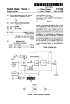
FIG. 1 is a diagrammatic view of a handheld laser scanner
of di?erent handheld scanners.
attached to a host computer according to the present inven
Heretofore there have been several systems for achieving
proper con?guration between the host computer and the
peripheral. In a typical system, a particular peripheral is
tion;
FIG. 2 is a diagrammatic view of an interface connector
system according to the present invention;
con?gured to work with a particular host computer or
terminal, that is, the peripheral has contained a single
label, which may for example be a bar code. contains
information or instructions by which the data reading device
35
FIG. 3 is a detailed diagrammatic view of a printed circuit
dedicated interface. Similarly, the host computer was con
board of FIG. 2;
?gured to accept only a particular type of peripheral. Any
FIG. 4 is a detailed diagrammatic view of an edge
connector as in FIG. 2;
FIG. 5 is a diagrammatic view of an alternate peripheral
time the peripheral was moved to a di?erent host computer,
it was necessary to replace the interface software and
hardware in the peripheral.
con?guration system;
The host computer may include a software selection
program in which the user inputs information identifying the
along line 6—6;
FIG. 6 is an end view of an end connector in FIG. 5 taken
particular peripheral enabling the system to have proper
operation. Such an operation requires the user to correctly
input information into the host computer identifying the
particular peripheral. Alternately, means are provided for
scanning a code on the outside of the peripheral which
informs the computer of the type of peripheral. Some
FIG. 7 is an end view of an end connector in FIG. 5 taken
45
FIG. 10 is an end view of an end connector in FIG. 9 taken
software provides the desired con?guration. Many of these
systems still require correct interface hardware.
In another con?gmration technique. the peripheral
along line 10—10;
FIG. 11 is an end view of an end connector in FIG. 9 taken
along line 11-11;
includes interface hardware for more than one host com
to be correctly linked to a host computer. Such hardware
con?guration may be etfectuated by manually actuable
external switches or by internal switches or “jumpers”
‘within the printed circuit board (and/OI‘ within the host
computer) which activate or deactivate certain components.
Such an operation typically requires the expertise of an
electronics technician or sldlled user and is not a desirable
?eld operation to be performed by the typical user. It is
FIG. 8 is a connector schematic illustrating an example
cable connection scheme for the cable connector of FIG. 5;
FIG. 9 is a diagrammatic view of an alternate peripheral
con?guration system;
peripherals actually include identifying signals which again
inform the particular host of the type of peripheral and
puter. When con?guring, the printed circuit board of the
peripheral requires certain hardware con?guration in order
along line 7-7;
55
FIG. 12 is a connector schematic illustrating an example
cable connection scheme for the cable connector of FIG. 9;
FIG. 13 illustrates an alternate cable connection embodi
ment;
FIG. 14 illustrates a cable scanning code operation; and
FIG. 15 illustrates various peripheral/host pairs.
DESCRIPTION OF THE PREFERRED
EMBODIMENTS
The preferred embodiments will now be described with
desirable to have an inexpensive and easy to use intercon 65 reference to the drawings.
nection system which can be effectively used by the average
user.
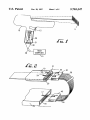
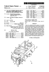
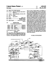
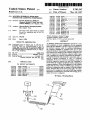
In FIG. 1. an example computer peripheral is illustrated as
a handheld laser scanner 10 used for scanning a bar code 11.
5,703,347
3
4
The scanner 10 is operably connected to a host interface
(diagrammatically illustrated as a computer 15) via an
interconnect cable 38. The interconnect cable 38 includes an
end plug or edge connector 30 which connects to a mating
connector 21 on the end of a printed circuit board 20 within
the edge connector 21 are thereby electrically connected.
and edge contacts #5 and #7 are also electrically connected.
By so electrically connecting these electrical contacts. cer
tain circuits within the circuit board 20 become electrically
connected resulting in a desired con?guration. The scanner
10 becomes con?gured to accept a particular host computer
15. The user has con?gured the scanner merely by plugging
the scanner 10. The interconnect cable 38 provides a com
munication link between the host computer 15 and the laser
scanner l0 and may also provide power to the scanner 10.
Referring to FIG. 2. the interconnect cable 38 has a ?rst
end connector 30 which plugs into the scanner 10 attaching
to the edge connector 21 of the circuit board 20. and a
in the correct interconnect cable 38.
A similar con?guration selection system may alternately
or in combination be applied to the host computer connec
tion side. The edge connector 40 has certain of its edge
second end connector 40 which plugs into the host computer
15 attaching to the edge connector 18. The ?rst end con
nector 30 includes tabs 34. 36 which slide into and mate with
corresponding slots 24. 26 in the body of the handle of the
scanner 10. Different types of scanners may be equipped
with ditferent positions of the slots 24, 26. Only an end
connector 30 having the correct con?guration of tabs 34. 36
will be correctly physically connectable to the scanner 10.
An interconnect cable 38 without the correct tab con?gura
tion cannot physically be plugged into the scanner 10.
Similarly on the host computer side of the interconnect
cable 38. the second end connector 40 is equipped with a tab
44 which mates with a corresponding slot 17 at the mating
edge connector 18 of the host computer 15. Only an end
connector 40 having the correct con?guration of the tab 44
will be correctly physically connectable to the host computer
20
interconnect cable 38.
In practice. the user would be provided with a single
peripheral. such as a scanner and several interconnect
cables. To connect the scanner, the user would merely select
25
30
as a laser scanner 10) to a particular host computer, a cable
having the correct tab con?gurations at both end connectors
must be selected. The unique physical con?gurations
the interconnect cable corresponding to the particular host
computer and plug it into the scanner. The interconnect cable
would then con?gure the scanner for the particular host
computer. To move the scanner to a di?’erent host computer,
the user would merely have to switch cables. The intercon
15. An interconnect cable 38 without the correct tab con
?guration cannot physically be plugged into the host com
puter 10.
Therefore in order to connect a particular peripheral (such
contacts 42 electrically connected, in the illustrated example
pins #5 and #7 of the edge connector 40 are jumped. When
the edge connector 40 is plugged into the edge connector 18
of host computer 15. edge contacts #5 and #7 within the edge
connector 18 become electrically connected, completing a
circuit within the host computer 15. thereby con?guring the
host computer 15 for the particular peripheral. The user may
therefore con?gure the host computer 15 for the particular
scanner 10 by merely selecting and plugging in the correct
35
ensures that the user must select the correct cable for the host
nect cable 38 may be provided with means for identifying
such as identifying markings 39 imprinted directly on the
interconnect cable 38 itself, color coding. a label with
identi?cation information connected to the cable 38, or the
like to assist the user in selecting the correct interconnect
cable for the given host.
The illustrated seven edge connector embodiment is a
computer and peripheral pair. The preferred embodiment
simpli?ed example for a connector design. Electrical contact
may only require tab con?guration on the host computer end
because it is not anticipated that the various handheld
scanners will require the dedicated interconnect cables. but
tab con?gurations on the peripheral end may be desired in
preferred scanner application. an interconnect cable plug
other peripheral applications. Further, the tab con?gurations
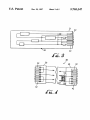
with 30 pins is set forth in Table A as follows:
con?gurations may of course be more or less than seven
contacts (and the two ends need not be the same). In a
illustrated are but one example means for ensuring proper
interconnect cable selection. The tabs and slots are readily
added to conventional end connectors. The design illustrated 45
does not prevent end connectors without tabs from connect
ing to the peripheral 10 and the host computer 15. but such
design may be modi?ed by one skilled in the art (such as by
reversing the positions of the slots/tabs) to prevent such
connection.
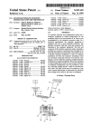
Referring to FIGS. 3 and 4. the printed circuit board 20
(located within the scanner 10) includes an edge connector
21 shown with seven edge contacts 22 (numbered 1 through
7). Though there is a distinction between edge contacts and
pins. for the purposes of the present invention, they are
Signal name
TEST_DATA
READ_DAT.A_WAND
STAKI‘_DATA
50
CLOCKIN
CLOCKOUT
RDATJLKI'N
SDATLRTN
CIDCK_IN__RTN
CIDCLOUT_RTN
VCC
55
interchangeable—a pin connector with its mating plug con
nector may be interchanged for an edge connector pair or
any other suitable electrical contact pair.
The board 20 is designed and constructed to be operable
with a number of host computers by way of an externally
VCC__OUT
VCC_IN
CIEALTO_SEND
TRANSMH'__DATA
REI'U'RNJATA
RETURNJ
DAIAQPLUS
DAM-MINUS
BEPJ
activated hardware con?guration provided by the intercon
nect cable 38. As viewed in FIG. 4. in the edge connector 30,
the edge contacts #5 and #7 are electrically connected.
illustrated as being “jumped”. Edge contacts #1 and #3 are
also jumped while edge contacts #2. #4 and #6 are used for
communication. When the interconnect cable 38 is plugged
into the printed circuit board 20. edge contacts #1 and #3 of
TABLE A
PWILEN
TRIGGER
65
BALCODE_OUT
GOOD_READ_IN
STARI'__OF_SCAN
M'I'RJAIL
Data Description(s)
5,703,347
5
6
switches 52 (dual inline package switches) or some other
type of switch. An interconnect cable equipped with
switches would have certain advantages as only one cable
version need be manufactured. The cable type correspond
TABLE A-continued
eg.ase
Signal name
Data Description(s)
ing to a particular peripheral would be selected by setting the
switches (by the manufacturer or by the skilled user) and the
cable could then stamped with an identifying code 39.
GROUND
CONFIG_l
CONFIGJ
CONFIGJ
CONFIG_4
As described above. the handheld data reader or other
computer peripheral is generally connected by a connector
cable to a given host or interface. The host or interface is
typically a host computer such as a central processing unit
(CPU) or other intermediate device which in turn commu
nicates with the CPU. The host may be a communication
The interconnect cable plug may use certain of the pins
for communication or power. Some of the pins may be
unused and available for other applications. it being desir
able that the same pin design be usable for diiferent con
?gurations. The last four pins #27480 are dedicated for
module. such as an RF transmitter which is provides a radio
15
providing the con?guration for the peripheral. The varia
tions of con?gurations are limitless and may be designed to
suit a particular application. The example in Table A is
provided in part to show the wide variety of con?gurations
that may be employed. By the cable con?guration scheme,
the peripheral may be con?gured setting for example com
munication baud rate. bit setting (8-bit. 16-bit etc.). parity or
some other parameter.
Though particular types of end connectors have been
described, the pin connector may be any suitable electrical
connector means for providing electrical contact including
plugs, pin connectors, sockets. edge connectors and the like.
20
216. The second end connector 224 is actually plugged into
30
electrical contact element.
The center of the interconnect cable 38 may comprise any
suitable transmission medium including a wire (as
illustrated). cable. ?ber optic cable. radio frequency link,
infra red light link, or other transmission medium.
The cable con?guration system described may be com
bined with other con?guration systems, some of which have
35
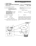
entry terminal 230. The key entry terminal 230 is in turn
connected by a suitable communication link 237 to the
central processing unit 240. In this arrangement. the host is
literally the wedge 240 but may be also be considered to
comprise a host assembly contained within the dashed-lined
box and designated by numeral 250.
such as a bar code laser scanner. a CCD reader or other
select a con?guration for a certain class or group of periph
erals. The peripheral may additionally include external (or
internal) switches identifying the particular peripheral
within the group thereby completing the described con?gu
ration.
45
In practice, a computer peripheral such as a laser scanner
10 will be equipped with hardware and firmware so that it
may be used with a plurality of ditferent host computers or
computer terminals. To provide
a translator module 235 (sometimes called a “wedge”)
which convm'ts the signal transmitted from the scanner 210
into a signal of the same form as that produced by the key
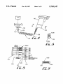
FIGS. 5-8 illustrate a preferred alternate embodiment in
which the peripheral is a handheld data reading device 110
been previously described For example. the interconnect
cable system described herein may be used to automatically
con?guration or
change con?guration when switching host computers. the
peripheral is con?gured merely by selecting the correct
interconnect cable 38. The electrically connected pins in the
network interface. into which the connector cable is
plugged. which is in turn connected to the host computer.
There are myriad of potential hosts for a given peripheral.
By way of another example. FIG. 13 illustrates a system in
which a handheld bar code scanner 210 is connected to a key
entry terminal 230. The interconnect cable 220 has a ?rst end
25
connector 222 plugged into the handheld bar code scanner
The end connector has multiple contacts. the contacts pro
viding the actual electrical contact surface. The contacts may
be pins. edge contacts. plugs. sockets. or any suitable
frequency communication link to the host computer. In such
an application. the cable is nonetheless connected to the host
computer or CPU albeit through the communication module.
If the peripheral is a printer for example. the host may be a
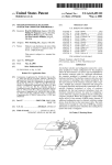
50
device. The scanner 110 is attached to a host, diagrammati
cally illustrated as a data terminal 140. by a connector cable
120 with a ?rst end connector 122 plugged into the scanner
110 and the second end connector 124 plugged into the data
terminal 140. The connector cable 120 is provided with a
label 135 which contains encoded data which may be read
by the data reader 110. The label 135 may. for example, be
a separate tag on which the bar code is imprinted or the bar
code may be imprinted directly on the cable 120 itself. As
described below. the label may also comprise an RFID tag
containing the pertinent programming data.
As best shown in FIG. 6. the ?rst end connector 122 is
illustrated as an edge connector having a plurality of edge
end connector of the interconnect cable provide the switch
ing necessary within the scanner l0. activating or deacti
contacts, including contacts 1220, 122b. for connection into
for the particular host computer.
pin connector having a plurality of pins (including pins
The interconnect cable 38 may be designed in any suitable
manner. In FIGS. 3 and 4 illustrate jump connections
between the respective edge contacts 32 of edge connector
124a, l24b) for connection into a corresponding connector
in the data terminal 140.
The cable 120 may also include an identi?cation label 139
which has identi?cation information to assist the user in
selecting the correct cable for the particular scanner and host
pair. Other or alternate selection means such as color coding
may be provided to assist the user in selecting the correct
a corresponding connector in the handle of the scanner 110.
vating certain circuits. thereby con?guring the scanner 10 55 FIGS. 5 and 7 illustrate the second end connector 124 as a
30 (or edge contacts 42 of edge connector 40). other
electrical connection mechanisms may be employed. The
contacts may be electrically connected by a simple hard wire
connection. The interconnect cable 38 itself may include a
printed circuit board 50. preferably in a unitary structure,
which may provides the desired electrical connection
between the pins. The interconnect cable 38 (or the printed
circuit board 50 thereon) may itself be equipped with dip
interconnect cable for the particular application.
65
FIG. 8 schematically illustrates an example cable connec
tion scheme 150 for the cable connector 120 of FIG. 5. Color
coded cable wires (Brown. Orange, Black. Yellow. Green.
5,703,347
7
8
White) provide desired elecuical communication path
scanned. However. according to the preferred embodiment
shown in FIG. 14. the user 305 need only select the correct
interconnect cable 320 and the correct bar code label 335 to
be scanned is automatically selected since it is on the cable
itself. Moreover. being on the cable. the bar code is readily
accessible and locatable without having to locate the user
manual. Though once the system has been initially
between edge contacts (nos. 10. 9. 18 etc.) in the ?rst end
connector 122 and respective pin contacts (nos. 4. 3. 7 etc)
in the second end connector 124. The cable connector 120
also includes peripheral con?guration selection by electrical
connector 121 (connecting edge contacts 14 and 13) and by
electrical connector 123 (connecting edge contacts 1 and
con?gured, the system will preferably store the con?gura
17).
tion information. if it becomes necessary to recon?gure. the
con?guration bar code 335 remains readily accessible on the
cable 320.
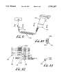
FIGS. 9-12 illustrate another preferred alternate embodi
ment in which the peripheral is a handheld data reading
device 155 such as a bar code laser scanner, a CCD reader
or other device. The scanner 155 is attached to a host
In order to ensure that a scanner is not inadvertently
recon?gured. a con?guration switch may be provided which
(diagrammatically illustrated as a data terminal 180) by a
connector cable 160 with a ?rst end connector 162 plugged
into the scanner 155 and the second end connector 164
plugged into the data terminal 180. The connector cable 160
is provided with a label 175 which contains encoded data
which may be read by the data reader 155. The label 175
may. for example, be a separate tag on which a bar code is
imprinted or the bar code label may be imprinted directly on
the cable 160 itself. As described in detail below. if required.
the user may at least partly con?gure the scanner 155 merely
must be actuated to place the scanner in programming mode.
Once the switch is actuated the scanner enters programming
mode enabling the programming label 335 on the cable to be
read and con?gure the scanner. The switch may be a
hardware switch such as a dip switch 312 (see FIG. 14) on
20
such as a switch label 337 located on the cable 320. Though
the con?guring bar code conveniently appears on the inter
connect cable. con?guration bar codes (i.e.. the same bar
by scanning the bar code label 175. An internal operation
code as appearing on the cable as well as additional bar
routine within the scanner 155 then con?gures the scanner
itself on the basis of the con?guration information provided
by the bar code.
25
codes) may nonetheless be provided in the user manual to
allow the user to con?gure the peripheral as desired such as
to speci?c user optional settings. Alternately. the program
As best shown in FIG. 10. the ?rst end connector 162 is
illustrated as an edge connector having a plurality of edge
ming label may be positioned on the host computer or
terminal. Such a location may be less desirable since dif
contacts. including contacts 1620. 162b, for connection into
ferent scanners may be plugged into the same host, possibly
a corresponding connector in the handle of the scanner 155.
FIGS. 9 and 11 illustrate the second end connector 164 as a
requiring diiferent programming labels. Alternately. the pro
gram switch label may be positioned on the host as shown
by the label 342 on the host 340 of FIG. 14. The user would
then scan the label 342 to switch to programming mode and
then scan the programming label 335 on the cable 320.
Con?guration on the basis of the encoded data instruc
tions obtained by reading the label or bar code 335 may be
plug connector (similar to the type conventionally used on
home telephones) having a plurality of wire connectors
(including wire connectors 164a. 164b) for connection into
a corresponding connector in the data terminal 180.
FIG. 12 schematically illustrates an example cable con
nection scheme 190 for the cable connector 160 of FIG. 9.
accomplished by a suitable internal con?guration routine.
For example, the routine may con?gure by way of selecting
proper internal switch settings or by selecting and running a
given protocol program. The data reader preferably stores its
con?guration parameters in a non-volatile programmable
Color coded cable wires (Brown. Orange. Black. Yellow,
Green. White) provide desired electrical communication
path between edge contacts (nos. 10. 9. 18 etc.) in the ?rst
end connector 162 and respective contacts (nos. 1. 2. 3. 4)
in the second end connector 164. The cable connector 160
memory such as EEPROM. These parameters may be set by
also includes peripheral con?guration selection by electrical
connector 161 (connecting edge contacts 14 and 13) and by
electrical connector 163 (connecting edge contacts 1 and
the housing of the scanner 310. Alternately. programming
mode may be entered (and exited if desired) by a soft switch
manual programming or reset by the con?guration routine.
45
The instructions from the label may cause the software in the
data reader to execute a series of commands resulting in the
17).
setting (or resetting) of the EEPROM-stored parameters.
In the preferred embodiment of the present invention as
shown in FIG. 14. the data reader device 310 is further (or
particular function for the peripheral. Possible con?guration
alternately) con?gured by reading a label having encoded
Con?guration selection or parameters change or set a
50
data thereon such as a con?guration bar code 335 which is
placed on the interconnect cable 320. By reading the con
?guration code 335. the scanner 310 (and/or the host 340) is
con?gured for the particular application on the basis of the
encoded instruction data by means of an internal con?gu
interface identi?cation (for a laser scanner. may include
Undecoded. IBM 4683, OCIA, RS-232. Wand
55
ration routine within the scanner 310 or the host 340.
US. Pat. Nos. 4.866.257 and 4.861.972 (herein incorpo
rated by reference) disclose examples on how a scanner may
be con?gured by scanning a bar code or by downloading
information from a host computer. Once the bar code has
been scanned or the control information. the con?gm'ation
information is stored in a memory (preferably a non-volatile
memory such as EEPROM) in the scanner so that repetitive
con?guration is not required and the con?guration of the
scanner is not lost when power is turned off. ‘Typically. the 65
bar codes are contained in the user manual and the user must
obtain the manual and then select the correct bar code to be
selections or parameters may include. by way of example for
a handheld scanner:
Emulation. etc);
communication parameters such as baud rate (2400 baud.
9600 baud etc); data format settings (parity. stop bits.
data bits). hardware handshaking (CTS/RI‘S), software
handshalcing (XonXotf). intercharacter delay (none. 10
ms. 20 ms etc). UPC Data Format (UPA-A. UPC-E.
Check Digit. Number System Digit)‘,
system speci?c parameters (pre?xes. su?ixes. symbology
identi?ers. etc);
reading restrictions, the instructions might restrict the set
of codes options that the decoder may have to handle;
by restricting the reading options. the operation speed
of the “autodiscrimination” algorithm (the means by
5,703,347
9
10
which the decoder ?gures out which code it is seeing)
may be increased as compared to requiring the algo
initiated for example by actuating the programming switch
312 on the device 310. Altemately. programming may be
rithm to consider all code types.
The preferred actual location on the cable for the encoded
automan'cally initiated upon power up or power down of the
device 310. In the power up example, when the device is
label will depend upon the particular application. Referring
powered up, the programming frequency signal would be
to FIG. 5 for example, the label 135 is located adjacent the
emitted and upon receipt the RFID tag would emit its signal
transmitting programming data to the device. Such a system
would not require the user to perform any act except plug in
second end connector. An alternate location is directly on the
second end connector 124 as shown by symbol label 133 on
end connector 124. If the second end connector 124 is too
small to practically accommodate the label 133 or if the
the correct cable and turn on the data reader and the data
10
connection location to the data terminal 140 provides incon
venient access. the label 135 may preferably be located up
the cable connector 120 at a suitable distance from the
second end connector 124. In general, it is impractical to
locate the label 135 on the ?rst end connector 122 or
immediately adjacent thereto because when the ?rst end
connector 122 is plugged into the scanner 155. the scanner
155 cannot be oriented to scan a label located immediately
reader itself would obtain the proper con?guration informa
tion for example) from the RFID tag on the cable and in this
example con?gure itself for the host device such as by
selecting the proper internal parameter.
An RFlD programming tag 343 may alternately be
located on the host device itself. By activating the program
ming sequence. the device 310 may receive the data from the
tag 343 identifying the host device 340 allowing the periph
eral device to be con?gured for that host device.
adjacent the ?rst end connector 122.
Nonetheless. in certain applications it may be desirable to
locate the label 135 near the ?rst end connector 122. If the
advantages have been disclosed. further advantages and
connector cable 120 is relatively long. for example 50 feet
(15 meters), the label may be preferably positioned about 2
modi?cations may become obvious to one skilled in the art
from the disclosures therein. The invention therefore is not
Thus, a peripheral con?guration system and method have
been shown and described Though certain examples and
feet (60 cm) from the ?rst end connector 122. Such a
position is close enough to be easily located but far enough
25
to allow convenient access. Such a location is illustrated in
FIG. 14 where the bar code label 335 is located on the cable
system with a particular host, comprising the steps of
identifying the data reader;
assembling the data reading system by selecting a corre
sponding interconnect cable, the interconnect cable
having a label associated therewith containing data
which may be read by the data reader, and connecting
320 at a convenient distance from scanner 310.
Though the cable connector con?grration embodiment
and the cable connector data reader con?guration embodi
ment may be used separately to con?gln'e the peripheral. the
embodiments may be combined together to provide a com
prehensive and readily implemented con?guration proce
a ?rst end of the interconnect cable to the data reader;
dure. By way of example, FIG. 15 illustrates a peripheral
shown as a laser scanner 410 is equipped with a multi 35
interface architecture which allows any one of many differ
ent types of host interfaces (such as a data terminal a ?xed
scanner or other point of sale unit 450, or a handheld key
entry unit 460) to be selected for a particular scanner. A cable
420 is selected corresponding to the particular scanner 410
a certain con?guration scheme in the scanner 410. The cable
420 may also con?gure the host interface. The cable 420
may be equipped with physical connector elements to ensure
that only the correct cable may be even physically plugged
into the host. Once plugged into the scanner and the host,
using the scanner itself. the operator then scans the label on
the cable which completes or con?rms scanner/host con
providing the data reading system with su?icient internal
hardware and/or ?rmware so as to be con?gurable for
at least two dilferent hosts;
connecting a second end of the interconnect cable to the
host;
con?guring internal hardware and/or ?rmware for the data
and the desired host interface (440, 450. 460) pair. In
practice, the user is supplied with a plurality of speci?c
connector cables which correspond to the possible scanner!
host pairs which the customer may have.
When plugged into the scanner, the cable 420 itself selects
to be limited except in the spirit of the claims that follow.
I claim:
1. Amethod for interfacing a data reader of a data reading
reading system by the steps of:
obtaining the data from the label with the data reader;
processing the data which contains instructions for
selection of internal hardware and/or ?rmware for
45
the data reading system. and
con?guring the data reading system for the particular
host on the basis of the instructions from the data.
2. A method according to claim 1 wherein the data reader
comprises a handheld laser scanner.
3. A method according to claim 1 further comprising the
step of ensuring a correct interconnect cable is selected for
the particular host and the data reader.
?guration.
4. A method according to claim 1 wherein the label
Besides the bar code label, there are other types of labels
comprises a bar code label and the data reader comprises a
or tags containing information which may be obtained by a 55 barcode reader.
reader device. One such label or tag is an RFID tag (radio
5. A method according to claim 1 further comprising
frequency identi?cation tag). The RFID tag is normally
providing the interconnect cable with a printed circuit board.
passive, but when activated or prompted by a signal from a
6. A method according to claim 5 wherein the step of
interrogator the RFID tag emits a signal with its information
con?guring the data reading system comprises switching a
to a receiving device. In one alternative embodiment, the
setting on the printed circuit board
cable 320 may include a label 336 comprising an RFID tag
7. A method according to claim 1 wherein the label is
instead of a bar code. The scanner 310 may comprise an
positioned on the interconnect cable.
RFID tag interrogator/receiva (either exclusively or in
8. A method according to claim 7 wherein the label is
combination with a bar code scanning mechanism) which
positioned on an end connector of the interconnect cable.
prompts the RFID tag 336 for its data and receives the data. 65
9. A method according to claim 1 wherein the label
The data is then used to set internal con?guration, function
comprises a radio frequency identi?cation tag and the data
or the like. The programming RFID tag process may be
reader comprises a radio frequency identi?cation reader.
5,703,347
12
11
having an interface con?guration different than the interface
10. A method for setting a function of a data reading
con?guration of the ?rst host, comprising
system comprising the steps of
having a label associated therewith containing data
which may be obtained by the data reader;
a data reader unit;
a ?rst interconnect cable connectable at a ?rst end thereof
to the data reader unit and connectable at a second end
thereof to the ?rst host. the ?rst interconnect cable
connecting a ?rst end of the interconnea cable to the data
reader and a second end to the given host device;
con?guring the data reading system for the interface
con?guration of the ?rst host;
selecting an interconnect cable corresponding to a data
reader and a given host device. the interconnect cable
activating the data reader and the given host device;
obtaining the data from the label with the data reader;
a second interconnect cable connectable at a ?rst end
thereof to the data reader unit and connectable at a
setting a function of the data reading system on the basis
of the data obtained from the label.
11. A method according to claim 10 wherein the data
reader comprises a handheld laser scanner.
12. A method according to claim 10 further comprising
the step of ensln'ing a correct interconnect cable is selected
for the given host device and the data reader.
13. A method according to claim 10 wherein the label
comprises a bar code label and the data reader comprises a 20
barcode reader.
14. A method according to claim 19 wherein the label
comprises a radio frequency identi?cation tag and the data
reader comprises a radio frequency identi?cation reader.
15. A method according to claim 10 wherein the step of 25
setting a function of the data reading system comprises
con?guring the data reading system for proper interface with
the given host.
16. A method according to claim 10 wherein the label is
positioned on the interconnect cable.
17. A method according to claim 16 wherein the label is
positioned on an end connector of the interconnect cable.
(1) identifying the data reader;
(2) identifying the given host/application for which the
data reader will be used;
(3) selecting a correct interconnect cable by identifying an
interconnect cable corresponding to the data reader and
the given host/application identi?ed in steps (1) and
a given host changing the interconnect cable and connecting
(2);
(4) con?guring the data reading system by connecting the
the interconnect cable to the data reader.
interconnect cable selected in step (3) to the data reader
and the host.
29. A method according to claim 28 wherein the step of
45
host/application identi?ed in steps (1) and (2).
30. A method according to claim 28 further comprising
50
22. Aperipheral system comprising a peripheral device. a
connector on the peripheral device. and a interconnect cable
detachably connectable to the connector. the interconnect
(5) using the data reader to obtain data contained by a
label on the interconnect cable;
(6) processing the data which contains instructions for
selection of interface con?guration parameters for the
cable being changeable by connecting to and being discon
23. A data reading system which is con?gurable to a ?rst
host having an interface con?guration and a second host
selecting the correct interconnect cable comprises selecting
an interconnect cable having an identifying code imprinted
thereon corresponding to the data reader and the given
host or class of hosts to which the interconnect cable
peripheral device.
cable corresponds.
28. A method for internally con?guring a data reading
data reader wherein hardware and/or ?rmware of the data
connect cable and connecting the interconnect cable to the
multiple contact connector constructed and arranged to be
properly physically connectable only to the second host or
similar class of hosts.
26. A data reading system according to claim 23 further
comprising means for ensuring correct selection of the
interconnect cable for the data reader.
27. A data reading system according to claim 23 further
system for a given host/application. comprising the steps of
reading system is automatically con?gured to interface with
?rmware of the peripheral system is automatically con?g
ured to interface with a given best by changing the inter
25. A data reading system according to claim 23 wherein
the second end of the second interconnect cable includes a
to a particular host or class of hosts to which the interconnect
30
able by being connecting to and being disconnected from the
nected from the peripheral device. wherein hardware and/or
the data reader comprises a handheld laser scanner.
of the interconnect cable, the identifying code corresponding
18. A multiple interface data reading system comprising a
corresponds.
for the interface con?guration of the second host.
24. A data reading system according to claim 23 wherein
comprising an identifying code located on an outer surface
data reader and an interconnect cable detachably connect
able to the data reader. the interconnect cable being remov
19. A system according to claim 18 wherein the intercon
nect cable includes a switch for changing con?guration of
the interconnect cable.
20. A system according to claim 18 wherein the intercon
nect cable includes a printed circuit board.
21. A system according to claim 18 further comprising an
identifying code located on an outer surface of the intercon
nect cable. the identifying code corresponding to a particular
second end thereof to the second host, the second
interconnect cable con?guring the data reading system
SS
data reading system;
(7) by means of an internal con?guration routine. con?g
uring the data reading system for the given application
by selecting proper internal parameter settings on the
basis of the instructions from the encoded data.