1
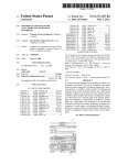
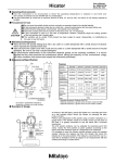
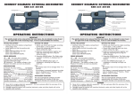
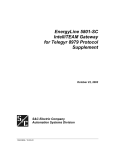
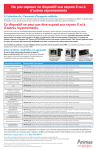
Small Tool Instruments and Data Management
Optical Remote Control Compatible, High-Accuracy Digital Indicator
DIGIMATIC INDICATOR ID-H
Bulletin No. 1817
World-Class Digital Indicator Delivers Higher
Measuring Accuracy and Multi-functionality
Digimatic Indicator ID-H
This new-generation digital indicator offers the excellent accuracy and functionality expected from this class of indicator. Take advantage of
its high accuracy backed up by 0.5µm resolution, remote control operation via a handheld controller (or RS-232C interface) and easy runout
measurements at a glance using the analog bar display.
Accuracy and Resolution Meet the Needs of High Accuracy Measurement
Resolution .000020" (0.5µm)
Accuracy 1.5µm (1.20"/30.4mm range), 2.5µm (2.40"/60.9mm range)
Measuring range:
1.20" (30.4 mm)
Measuring range:
2.40" (60.9 mm)
543-562A (inch)
543-564A (inch)
543-561A (mm)
543-563A (mm)
Note that the Inspection Certificate
supplied with each instrument,
which assures product quality and
safety, cannot be used for obtaining
a Calibration Certificate since the
purchase date is not stated.
Functionality Meets the Needs of Diverse Measurement
• Tolerance judgment
• Large characters
OK, +NG or -NG is shown for a measurement based on the
upper/lower limit values currently set. If an out-of-tolerance value
is detected, the backlight turns red to help with workpiece sorting
operations.
The 7-digit digital display uses large characters for ease of reading.
• Maximum/minimum value based measurement
A comparison measurement can be made on the basis of the
detected maximum or minimum values that has been zero-set. For
example, this method is convenient for measurement in which the
maximum value at a workpiece peak is zero-set and other values are
measured in comparison with this vaue.
• Remote operations
The indicator can be operated remotely by using the remote
controller, or a personal computer via the built-in RS232C interface.
• Analog bar display
• Two ways of measuring
The analog bar display makes it easy to quickly find maximum/
minimum readings.
Seven ranges from ±.0004" to ±3.15" (±0.01mm to ±80mm) can
be selected to suit the task at hand.
• Function lock
A measurement can be made relative to zero (Incremental) or relative
to an arbitrary value entered into the display (Absolute), whichever is
most convenienent.
The setting conditions can be locked to prevent them being
accidentally changed during use.
• Resolution switching
The resolution can be selected to be .00002" (0.0005mm) (0.5µm)
or .00005" (0.001mm) (1µm).
• Measuring maximum value, minimum value and
runout
Maximum value/minimum value measurement
Maximum or minimum values are automatically held and displayed.
• Direction switching
The counting direction can be reversed.
• Selectable output mode
Difference/Runout
measurement
Difference (or Total Runout, on a circular
workpiece) between a maximum and a
minimum value is held and displayed. The
maximum/minimum values are stored in
memory and can also be displayed.
This indicator not only supports simple
recording of measurement data using
the well-established Digimatic output,
but also enables integration into a
measurement system through advanced
control via the RS-232C interface.
Example: Indicator travel from points A to D
Difference (or Total Runout) is displayed as A. Dimensions B
(maximum value) and C (minimum value) can be recalled from
memory with a simple key sequence.
The spindle can be lifted up to 1.20"
(30mm) without touching the indicator
body by using the dedicated spindle lifting
cable (optional accessory). The spindle
can be lifted over the full stroke by using
the lifting knob (optional accessory) that
attaches to the top of the spindle.
• Remote spindle lifting
C
B
Point D
Point A
A
Point B
Point C
Lifting knob
Operation with the Remote Controller (Option)
Operations such as zero-setting and presetting can be made without touching the indicator, thereby
avoiding disturbance to the set-up. Also, if multiple indicators are used in an integrated measurement
system then an arbitrary ID number can be set for each one in order to enable remote operation of a
specific indicator, or remote operation of
all indicators.
Main Functions
• Advantages of remote control
Remote operation without contact with the indicator body ensures
stable measurement. Additionally, the remote controller supports
measurement in situations where access to indicators is difficult.
If indicators are used for multipoint
measurement, the remote controller is
convenient for measurements on multiple
axes since the controller can set multiple
indicators to zero concurrently.
If the remote controller ID is set to '00',
the controller operates all indicators. If the
controller ID is set to the ID of one indicator
group, the controller operates only that
specific group of indicators. Up to 14 group ID
numbers can be set up in the controller.
• Measurement mode
switching: Switches
between the different
types of measurement
(normal, maximum/
minimum, and runout).
• Zero-setting: Sets
the display to zero
at any arbitrary
position (Incremental
measurement).
• Preset value recall:
Recalls a preset value
entered into memory
(Absolute measurement).
• Peak value reset: Resets
the maximum value,
minimum value or runout value already
stored so the indicator is ready to make the
next measurement.
• Data output: Outputs measurement data to
an external device.
Building an Advanced Control System via the RS-232C Interface
An advanced, remote control system can be manufactured with the built-in RS-232C interface and a PC.
A stable, high-accuracy measurement system can be implemented without touching any indicator in
the system. (Optional, dedicated cables are required.)
• RS-232C Specifications
· Since the indicator supports RS-232C
interface commands with key operations,
the indicator can be operated from the PC
using these commands. It is also possible
to perform statistical processing and
management of measurement data by
installing a control program in the PC.
5 4 3 2 1
Receptacle
D-sub 9-pin (female)
Inch screw thread specification
9 8 7 6
1. Pin assignments in the dedicated cable.
Pin
No.
1
2
3
4
5
6
7
8
9
Signal
name
N.C.
TXD
RXD
DSR
GND
DTR
CTS
RTS
N.C.
Input/
Output
–
OUT
IN
IN
–
OUT
IN
OUT
–
Definition
(Purpose)
No connection
Transmit data
Receive data
Data set ready
Ground
Data terminal ready
Clear to send
Request to send
No connection
2. Communication protocol (EIA/TIA232
compatible)
Home position
DCE (modem definition),
dedicated cable to be used.
Half-duplex, TTY protocol
Communication
method
Baud rate
4800, 9600bps
Bit configuration Start bit: 1
Data bit: (7 or 8) ASCII,
upper case
Parity bit: None, even, or
odd
Stop bit: 2
Communication Setting with a parameter
condition setting
Specifications
External Dimensions
543-562A
.67 lbs
290g
120V, 50/60Hz AC adapter (6V, 1A)
305g
Up to 6 digits can be output from the Digimatic port, with truncation from the leading
digit if greater than this limit. For example, if the display shows the 7-digit value
'123.4565', only '23.4565' would actually be output.
3.54" (90)
4.49" (114)
12.26" (311.3)
0
(ø8 -0.009
)
Screw portlon
on the contact point
4-48 UNF (M2.5 (P=0.45)x5)
2.36"
(60)
0
(ø8 -0.009
)
.29"
(7.3)
.64 lbs
3.04" (77.3) 1.18"
(30)
2.40" (60.9)
Contact point
Operating temperature range
Storage temperature range
Main unit mass
Power supply
2.36" (60)
7-digit LCD, sign, and analog bar
with 2-color backlight
Sphere R=.06" (1.5mm) (cemented carbide)
32°F to 104°F (0°C to 40°C)
14°F to 140°F (-10°C to 60°C)
2.36"
(60)
.29"
(7.3)
Display
ø.47" (ø12)
4.49" (114)
Positional detection method
Maximum response speed
ø.47" (ø12)
9.89" (251.3)
Displacement accuracy
(at 20°C)
Quantizing error
Measuring force
Measuring orientation
543-564A
Unit: inch (mm)
543-562A
543-564A
543-561A
543-563A
1.2" (30.4mm)
2.4" (60.9mm)
30.4mm
60.9mm
Switchable between .00002"
Switchable between 0.0005mm
(0.0005mm) and .00005" (0.001mm)
and 0.001mm
.00006"
.0001"
0.0015mm
0.0025mm
(0.0015mm)
(0.0025mm)
±1 count
2.0N or less
2.5N or less
2.0N or less
2.5N or less
Between vertical (spindle pointing down)
and horizontal
Photoelectric-type reflection linear encoder
39.37in/sec. (1000mm/sec.)
1.86" (47.3) 1.18"
(30)
1.20" (30.4)
Order No.
Measuring range
Resolution
Screw portlon
on the contact point
4-48 UNF (M2.5 (P=0.45)x5)
Accessories
Standard Accessories
Optional Accessories
• User's Manual
• Inspection Certificate
• Lifting Lever
(Knob)
• AC Adapter
1 Remote Controller
2 Spindle Lifting Cable
Lifting amount: 1.18" (30mm)
3 Lifting Knob
4 Digimatic Connecting Cable 40" (1m)
5 Digimatic Connecting Cable 80" (2m)
6 RS-232C Connecting Cable 80"(2m)
7 Lug-on-Center Back
8 Digimatic Mini Processor/Printer
9 Digimatic Presetter
Recommended Stands
21EZA099
540774
(for 543-562A & 543-564A)
• Granite Comparator Stand
21EZA101
936937
965014
21EAA131
101306
264-504-5A
543-003
• Comparator Stand
517-890
215-514
• Comparator Stand
215-831
* Mitutoyo will accept a special order for an air lifter upon request.
6
8
4
1
215-514
2
9
3
7
1.22"
(31)
.43"
11)
Bore Micrometers
Note: All our product details, in particular the illustrations, drawings, dimensional and performance details and other technical specifications
contained in this publication are to be considered to be approximate average values. To this extent, we reserve the right to make changes in design,
technical data, dimensions and weight. Our specified standards, similar technical rules and technical specifications, descriptions and illustrations of the
products are correct at the time of printing. The current version of our general terms and conditions also apply. Only offers which we have submitted
can considered to be definitive.
© 2005 Mitutoyo America Corporation, Aurora IL
We reserve the right to change specifications and prices without notice.
0105-10 • Printed in USA • April 2005