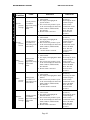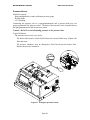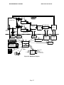
1
WATERS MEDICAL SYSTEMS Page 1 WATERS MEDICAL SYSTEMS RM3 Instruction Manual Customer Service Waters Medical Systems provides toll free telephone support to assist you with product information and placing orders for instruments, parts and disposable components. The same toll free number can be used for technical and non-technical support by requesting the Technical Support Center. Customer Service: 800-426-9877 8:00 AM to 5:00 PM CST 507-252-3700 Facsimile Returning Equipment Most questions can be answered over the telephone. In some situations, you may need to return your instrument to Waters. Call Waters Customer Service for the RGA# and shipping information. If possible, return the RM3 to Waters in the original shipping packaging. The original packaging will minimize delays and shipping damage. It is strongly recommended that the RM3 is insured for full purchase price in case of damage. Waters is not responsible for return shipping damages. All parcels should be shipped to our Rochester street address. WARNING: DO NOT SHIP THE RM3 BACK WITH THE 12V BATTERIES INSIDE. SEVERE DAMAGE WILL RESULT TO THE RM3 AND VOID WARRANTY. Parcels: Waters Medical Systems RGA # ___________ 2411 7th Street NW Rochester, MN 55901 Federal law restricts this device to sale by or on the order of a physician. 3070024.001 Rev. 2 October 23, 2003 Page 1 WATERS MEDICAL SYSTEMS RM3 Instruction Manual Warranty Waters Medical Systems warrants that during a period of one year from date of shipment from the factory, each new instrument sold or manufactured by Waters is free from defects in material or workmanship under normal installation, use and service. Waters Medical Systems agrees that any such defect shall be repaired or replaced at Waters discretion, provided the part is delivered intact to the factory for examination with shipping costs prepaid by the owner. Exceptions to this warranty include items or parts that require periodic replacement or calibration consistent with normal use and instructions. Such items or parts are not covered under this warranty. This warranty does not extend to any instrument, which has been subjected to negligence, accident, abuse, misuse or other improper operation, or has been tampered with or altered or repaired by anyone other than an authorized service representative of Waters Medical Systems. The purchaser assumes all liability for all claims, losses or damages incurred by the use or misuse of the instrument, when placing and accepting delivery of an instrument, supporting parts or disposables. AT NO TIME SHALL WATERS MEDICAL SYSTEMS, A DIVISION OF WATERS INSTRUMENTS, INC., THEIR EMPLOYEES, REPRESENTATIVES OR THEIR DEALERS BE LIABLE FOR ANY INCIDENTAL OR CONSEQUENTIAL DAMAGES RESULTING FROM OR CAUSED BY ANY DEFECT, FAILURE OR MALFUNCTION OF ANY PRODUCT, OR CLAIMS LOSSES, DAMAGES OF ANY THIRD PARTY OR FOR LOST PROFITS OR INDIRECT OR CONSEQUENTIAL DAMAGES OF ANY KIND EVEN IF WATERS HAS BEEN INFORMED OF THE POSSIBILITY OF SUCH DAMAGES. THIS WARRANTY IS GIVEN EXPRESSLY AND IN LIEU OF ALL OTHER WARRANTIES, EXPRESSED OR IMPLIED. PURCHASER AGREES THAT THERE IS NO WARRANTY OF MERCHANTABILITY AND THAT THERE ARE NO OTHER REMEDIES OF WARRANTIES, EXPRESSED OR IMPLIED, WHICH EXTEND BEYOND THE DESCRIPTION ON THE FACE OF THIS AGREEMENT. SOME STATES DO NOT ALLOW LIMITATIONS ON THE DURATION OF IMPLIED WARRANTIES, OR EXCLUSION OR LIMITATION OF INCIDENTAL OR CONSEQUENTIAL DAMAGES FOR CERTAIN PURCHASES, SO THE ABOVE EXCLUSIONS OR LIMITATIONS MAY NOT APPLY TO YOU. THIS LIMITED WARRANTY GIVES YOU SPECIFIC LEGAL RIGHTS, AND YOU MAY ALSO HAVE OTHER RIGHTS WHICH VARY FROM STATE TO STATE. Page 2 WATERS MEDICAL SYSTEMS RM3 Instruction Manual Table of Contents FIGURE INDEX........................................................................................................................................... 5 INTRODUCTION ........................................................................................................................................ 6 STATEMENT OF INTENDED USE.......................................................................................................... 7 GENERAL SAFETY POINTS .................................................................................................................... 8 THE RM3 ...................................................................................................................................................... 9 THE CASSETTE........................................................................................................................................ 11 GETTING STARTED................................................................................................................................ 13 DEFINITION AND GENERAL DESCRIPTION OF CONTROLS .......................................................................... 13 On/Stand By ........................................................................................................................................ 13 Stroke Volume Knob............................................................................................................................ 13 MENU STRUCTURE ................................................................................................................................ 14 MAIN MENU ............................................................................................................................................. 14 SYSTEM MENU ......................................................................................................................................... 16 Pulse Pump ......................................................................................................................................... 16 Air Pump ............................................................................................................................................. 16 Circ Pump ........................................................................................................................................... 16 Zero Sensors........................................................................................................................................ 16 Erase Trends ....................................................................................................................................... 17 Trend ................................................................................................................................................... 17 Battery Status ...................................................................................................................................... 17 UNOS/ID Number ............................................................................................................................... 17 Flow .................................................................................................................................................... 17 RS-232 Transfer .................................................................................................................................. 17 Set Clock ............................................................................................................................................. 17 Circ Temp............................................................................................................................................ 17 DIAGNOSTIC MENU .................................................................................................................................. 18 RS232 Test .......................................................................................................................................... 19 Printer Test ......................................................................................................................................... 19 Memory Test........................................................................................................................................ 19 Factory Default ................................................................................................................................... 19 Temperature Adjust............................................................................................................................. 20 Show Errors ........................................................................................................................................ 20 Clear Errors........................................................................................................................................ 20 Battery Voltages.................................................................................................................................. 20 Version ................................................................................................................................................ 20 DISPLAY MENU ........................................................................................................................................ 21 Trends ................................................................................................................................................. 21 Selecting a Trend for Display ............................................................................................................. 21 Brightness ........................................................................................................................................... 22 ALARM MENU .......................................................................................................................................... 22 Turning off the alarms......................................................................................................................... 22 Turning on the alarm .......................................................................................................................... 23 Changing individual alarm limits ....................................................................................................... 23 Changing the default alarm limits....................................................................................................... 23 Remote Alarm...................................................................................................................................... 24 RM3 Alarm Condition Table............................................................................................................... 25 PRINT MENU ............................................................................................................................................. 26 PUMP MENU ............................................................................................................................................. 26 Page 3 WATERS MEDICAL SYSTEMS RM3 Instruction Manual SYSTEMS ................................................................................................................................................... 27 MEASURING FLOW WITH THE RM3........................................................................................................... 27 How the Flowprobes Work.................................................................................................................. 27 Attaching the Flowprobes ................................................................................................................... 27 Direct Timer Method........................................................................................................................... 28 PRESSURE MEASUREMENTS ...................................................................................................................... 29 PRINTER.................................................................................................................................................... 30 CIRCULATION (CIRC) PUMP AND RESERVOIR .......................................................................................... 31 BYPASS CONTROL .................................................................................................................................... 33 AIR PUMP ................................................................................................................................................. 33 Gas Mixtures ....................................................................................................................................... 33 DC POWER ............................................................................................................................................... 34 BACK-UP BATTERIES ................................................................................................................................ 35 OPERATIONAL CHECKLIST................................................................................................................ 36 RM3 CHECKLIST ...................................................................................................................................... 36 MAINTENANCE........................................................................................................................................ 38 CLEANING ................................................................................................................................................ 38 PULSE PUMP ............................................................................................................................................. 38 CLEANING AND STERILIZATION OF TRANSONIC ® FLOWPROBES ............................................................... 39 Preparation of Probes for Sterilization............................................................................................... 39 BATTERIES AND CHARGING ...................................................................................................................... 41 Main Batteries..................................................................................................................................... 41 Battery Shelf Life & Storage ............................................................................................................... 41 RAM Back-up Batteries....................................................................................................................... 42 APPENDIX A: TROUBLESHOOTING ................................................................................................. 43 APPENDIX B: SENSOR VERIFICATION............................................................................................ 48 RECOMMENDED TEST METHODS .............................................................................................................. 48 Flowmeter ........................................................................................................................................... 48 Pressure Sensor................................................................................................................................... 49 Temperature Sensor ............................................................................................................................ 50 APPENDIX C: TRANSMITTING DATA TO YOUR COMPUTER ................................................... 51 SETTING UP FOR MICROSOFT WINDOWS® FOR THE FIRST TIME:................................................................ 51 TRANSFERRING DATA NEXT TIME ............................................................................................................ 53 APPENDIX D: RM3 FUNCTIONAL DIAGRAM ................................................................................. 54 APPENDIX E: SPECIFICATIONS.......................................................................................................... 56 GENERAL FEATURES ................................................................................................................................. 56 SIZE .......................................................................................................................................................... 56 WEIGHT .................................................................................................................................................... 56 POWER...................................................................................................................................................... 56 COOLANT CAPACITY ................................................................................................................................. 56 GRAPHIC DISPLAY .................................................................................................................................... 56 RECORDER ................................................................................................................................................ 56 ULTRASONIC FLOWMETER ........................................................................................................................ 56 TEMPERATURE SENSOR ............................................................................................................................ 56 PRESSURE TRANSDUCER ........................................................................................................................... 56 PERFUSATE PUMP ..................................................................................................................................... 56 REMOTE ALARM RELAY ............................................................................................................................ 56 Page 4 WATERS MEDICAL SYSTEMS RM3 Instruction Manual FIGURE INDEX Figure 1 RM3 Control Unit and DCM-100 Cassette................................................................................... 10 Figure 2 RM3 Control Unit ......................................................................................................................... 10 Figure 3 DCM-100 Cassette........................................................................................................................ 11 Figure 4 Main Menu Screen ........................................................................................................................ 13 Figure 5 Stroke Volume Knob ..................................................................................................................... 13 Figure 6 Main Menu Display ...................................................................................................................... 14 Figure 7 RM3 Menu Structure..................................................................................................................... 15 Figure 8 System Menu ................................................................................................................................. 16 Figure 9 Diagnostic Menu........................................................................................................................... 18 Figure 10 RM3 RS232 connection to host PC ............................................................................................. 19 Figure 11 Test Strip..................................................................................................................................... 19 Figure 12 Display Menu.............................................................................................................................. 21 Figure 13 Alarm Menu ................................................................................................................................ 22 Figure 14 Side Panel with Remote Alarm Cable ......................................................................................... 24 Figure 15 Sensaphone® Phone Dialer........................................................................................................ 24 Figure 16 Print Menu .................................................................................................................................. 26 Figure 17 Pump Menu................................................................................................................................. 26 Figure 18 Transonic Flowprobe Transducer .............................................................................................. 27 Figure 19 Attaching Flowprobes................................................................................................................. 27 Figure 20 Clamping Tube for Direct Flow Method..................................................................................... 28 Figure 21 Mean Calculation Formula......................................................................................................... 29 Figure 22 Bubble trap with fluid line shown ............................................................................................... 29 Figure 23 Loading paper into the printer.................................................................................................... 30 Figure 24 Circulation Pump and Reservoir ................................................................................................ 31 Figure 25 Draining the coolant tank ........................................................................................................... 32 Figure 26 Bypass Panel............................................................................................................................... 33 Figure 27 RM3 Control Unit ....................................................................................................................... 34 Figure 28 RM3 Control Unit ....................................................................................................................... 35 Figure 29 Installation of RAM Back-up Batteries ....................................................................................... 42 Figure 30 Testing the flowmeter.................................................................................................................. 48 Figure 31 Testing the pressure sensor......................................................................................................... 49 Figure 32 Testing temperature probe.......................................................................................................... 50 Figure 33 Sample Spreadsheet of Trend Data............................................................................................. 53 Figure 34 RM3 Block Diagram ................................................................................................................... 55 Page 5 WATERS MEDICAL SYSTEMS RM3 Instruction Manual INTRODUCTION Waters Medical Systems’ RM3 Renal Preservation System is a two-part kidney preservation system which includes (1) a control unit (the RM3) for pulsatile perfusion and monitoring of one or two kidneys and (2) a sterile, disposable, single-use cassette designed to circulate the perfusate through the kidney(s). The RM3 control unit is a selfcontained unit for monitoring or transportation of kidneys and controls the cassette functions. The cassette is a circulation system consisting of an organ chamber, venous and arterial reservoirs, bubble trap, oxygenator, heat exchanger and pulsatile pump head. The cassette can provide circulation of up to one liter of perfusate to one or two kidneys, attached either singly or en bloc. Page 6 WATERS MEDICAL SYSTEMS RM3 Instruction Manual STATEMENT OF INTENDED USE The RM3 Renal Preservation System was developed by Waters to maintain kidneys for transplant. The device provides a simple and efficient method for hypothermic pulsatile preservation for one or two kidneys by maintaining pressure, flow and temperature. It is not to be used for direct contact to any patient. Clinical experience has proven that hypothermic pulsatile preservation of kidneys for transplant is a safe, effective and cost efficient means of preservation.1,2 Pressure, flow and temperature are under control and displayed continuously for evaluation by the operator. The components, options and supplies of the RM3 are intended to be used for the hypothermic pulsatile perfusion of kidneys. These products are to be used in accordance with the instruction manual, associated documents and accepted medical standards. Only accessories and supplies purchased from or recommended by Waters Medical Systems are to be used with the RM3. In addition, only preservation solutions designed specifically for pulsatile perfusion should be used with the RM3. Use of supplies other than Waters Medical Systems may result in less than optimal performance and may invalidate the warranty. 1 “Immediate Function and Cost Comparison Between Static and Pulsatile Preservation in Kidney Recipients”, J.A. Light, F. Gage, A.E. Kowalski, T.M. Sasaki, C.O. Callendar, Clinical Transplantation 1996; 10:233-236. 2 “Efficacy of Clinical Cadaver Kidney Preservation by Continuous Perfusion”, R.M. Hoffman, R.J. Stratta, H.W. Solinger, M. Kalayoglu, J.D. Pirsch, F.O. Belzer; Transplant Proceedings, Vol. XX, No 5 (October) 1988; pp 882-884. Page 7 WATERS MEDICAL SYSTEMS RM3 Instruction Manual GENERAL SAFETY POINTS The RM3 must be placed on a flat and level surface with adequate space for easy access to the power switch, accessories, and the ice chest. Do not autoclave the RM3. Visually inspect the power cord and all accessory cables for broken or frayed connectors or wires. The use of any broken or frayed accessories or cables can cause a loss of signal or interference. Visually inspect the cassette to make certain that all connectors and tubing are secure before attaching the cassette to the RM3. Do not block the vent holes in the back or under the cabinet. The RM3 and cassette should be positioned at a height for easy viewing of the kidneys and the display. WARNING: Explosion risk. anesthetics. Do not use the RM3 in the presence of flammable CAUTION: The RM3 must be connected to a receptacle marked Hospital Grade. CAUTION: Refer servicing to qualified service personnel. Page 8 WATERS MEDICAL SYSTEMS RM3 Instruction Manual THE RM3 The RM3 control unit regulates the pulsatile perfusion of the perfusate. The RM3 will perfuse and monitor real-time pressure, flow and temperature of the perfusate. It will display all parameters that it monitors for visual confirmation of perfusion activity and trend that data for objective evaluation of the kidney prior to transplantation. The user can select the data and waveforms to print. The RM3 control unit has variable stroke volume control, allowing the operator to mechanically adjust the occlusion of the pulsatile pump arm. By turning the stroke volume knob clockwise, the volume of perfusate from the pump head to the kidneys is increasing along with a corresponding increase in pressure. The RM3 operates on 90-253 VAC, 47 to 440 Hz, auxiliary 12 volt DC supply or rechargeable 12V lead acid battery(s) to provide continuous power. Battery operation lasts up to approximately 2 hours with a single lead acid battery or four hours with two batteries. The display screen is divided into three sections. During normal operation the largest section will display the real-time analog waveform, the menu or the trend graphs. A second section will display the numerical information which includes systolic, mean and diastolic pressures, flow from both the right and left kidneys, temperature of the perfusate, renal resistance of the right and left kidneys and the pump pulse rate. The digital information will remain displayed at all times during an alarm, menu selection or printing. The third section displays the identification of the menu keys located on the front panel overlay. The alarm system will signal an audio as well as a visual alarm for the user selected alarm conditions. A remote alarm connection can be used to alert technicians not in immediate attendance. Page 9 WATERS MEDICAL SYSTEMS RM3 Instruction Manual Figure 1 RM3 Control Unit and DCM-100 Cassette Figure 2 RM3 Control Unit Page 10 WATERS MEDICAL SYSTEMS RM3 Instruction Manual THE CASSETTE The MOX DCM-100 cassette is a gravity flow system circulating perfusate through the kidneys. The perfusate is pumped from the arterial reservoir, through the heat exchanger to the bubble trap where it is delivered to the cannulated kidney(s). The perfusate returns to the arterial reservoir by gravity through the right and left venous reservoirs and the membrane oxygenator. The cassette is easily mounted on the RM3 by the mounting brackets on the left front and right rear connectors on the cassette. Position the pulsatile pump head into the pump arms of the RM3. Connect the pressure transducer line, inlet tubing to the ambient air pump, temperature probe cable and the flow transducers to the RM3. To complete the installation, connect the heat exchange lines from the ice water bath or the refrigeration unit to the cassette. For the most efficient operation, the inlet connection is located on the top and the outflow connection on the bottom. A temperature probe located in the bubble trap will control a circulation pump located in the ice water bath and thermostatically maintain the temperature of the perfusate. Figure 3 DCM-100 Cassette Page 11 WATERS MEDICAL SYSTEMS RM3 Instruction Manual The bubble trap separates any trapped air bubbles from the perfusate to prevent air bubbles from reaching the kidneys. It also provides mounting positions for the perfusate temperature probe and the pressure transducer line. Since the bubble trap is operated at the perfusion pressure, it is critical to insure that there are no air leaks in the pressure system. It is recommended that all tubing connectors are tie-strapped for airtight connections. Sample ports are located on the bubble trap. The syringe access pressure port allows the operator to regulate the proper perfusate level at all times. By inserting a needle and syringe into the pressure port and either infusing or withdrawing air, the perfusate level can be moved up or down. The sample port below the perfusate level indicator line can be used to infuse products or remove a sample of the perfusate. A persistently rising fluid level indicates a leak in the pressure system. The perfusate level should be at the indicator line at all times for accurate pressure measurements. Perfusate migrating down the pressure transducer line will damage the transducer. Use the hydrophobic filter (WPN 3180003.005) during each operation of the RM3. The pulse pump arm of the RM3 control unit and the pump head in the cassette provide pulsatile flow. The pump head includes a pair of occlusive valves placed in series and is alternately compressed and released by the cam-driven arm of the pump arm. The pump head must be placed in the pump arm assembly with the holding brackets positioned directly at the base of each valve in the pump head. During initial priming of the cassette, some air may be trapped in the pulsatile pump head. To remove this air, the discharge end of the cassette (the nearest the coolant source) should be raised from the top of the RM3 and held at an upward angle while manually squeezing the pump head. The RM3 control unit has variable stroke volume control, allowing the operator to manually adjust the occlusion of the pulsatile pump arm. By turning the stroke volume knob clockwise, the volume of perfusate from the pump head to the kidneys is increased along with a corresponding increase in pressure. The flow from each kidney is collected in the respective venous reservoirs; the flow from the right half of the cassette flows into the left venous reservoir, flow from the left, into the right reservoir. These reservoirs are calibrated in 20cc increments. The flow rate is measured by timing the flow from each kidney into the venous reservoir. The graduated marking on the venous reservoirs of the cassette are provided to permit direct measurement of the perfusate. DO NOT PLACE FINGERS INTO THE PULSE PUMP ARM OF THE RM3 CONTROL UNIT WHILE THE PUMP IS IN OPERATION. MAKE SURE YOUR FINGERS ARE CLEAR BEFORE TURNING ON THE PULSE PUMP. The perfusate in the cassette can be cooled by either the ice water bath in the RM3 or by means of an auxiliary refrigeration system. The ice water bath will maintain the hypothermic perfusate temperature for approximately three hours at 7°C at an ambient temperature of 22°C. After that time, the excess coolant will need to be drained and the ice replaced. Page 12 WATERS MEDICAL SYSTEMS RM3 Instruction Manual GETTING STARTED Definition and General Description of Controls On/Stand By The POWER switch is located on the right side panel of the RM3. When the RM3 POWER switch is moved to the ON position, the Main Menu will be displayed. ET: 10:25 12:00 PPM TEMP 60 70 35 7° SYS MEAN DIA 40 26 20 0 Pressure mmHg Trend: OFF Batt1: OPEN Batt2: OPEN RAMBat BAD ALARM SUSPENDED SYSTEM DISPLAY ALARM Flow L Flow R 120 100 RR L RR R .22 .26 PRINT PUMP Figure 4 Main Menu Screen Stroke Volume Knob The STROKE VOLUME KNOB is located above the recorder and controls the mechanical pump arm of the RM3. Rotating the control clockwise increases the volume and pressure of perfusate delivered to the kidneys. The stroke volume knob can be secured into position by rotating the knob lock to the right. Figure 5 Stroke Volume Knob Page 13 WATERS MEDICAL SYSTEMS RM3 Instruction Manual MENU STRUCTURE MAIN MENU After powering the RM3 ON, the RM3 will display the MAIN MENU, which is the normal operation display for the RM3. The digital data is displayed on the right side of the screen and a current waveform is displayed on the left side. The digital information is continuously displayed and updated in any mode during operation. PPM ET: 10:25 12:00 TEMP 60 70 35 7° SYS MEAN DIA 40 26 20 0 Pressure mmHg Trend: OFF Batt1: OPEN Batt2: OPEN RAMBat BAD ALARM SUSPENDED SYSTEM DISPLAY ALARM Flow L Flow R 120 100 RR L RR R .22 .26 PRINT PUMP Figure 6 Main Menu Display Menu Keys The RM3 menu system operates from the five keypad switches below the display. Their function is displayed on the bottom of the screen and their function changes depending on which menu is active. Press MAIN in any menu to return to the start of the menu system. The SELECT key will allow you to change the action highlighted on the menu. The SYSTEM MENU selects the monitoring parameters and limits, the UNOS identification number, and manual or automatic time flow, then transfers data to the RS232 port. The DISPLAY MENU will set the screen for viewing. The ALARM MENU will set the alarm and default limits. The PRINT MENU will print the analog pressure waveform in real-time or the selected trend graph. The PUMP MENU controls the pulse pump rate and turns the pulse pump on or off. Page 14 WATERS MEDICAL SYSTEMS RM3 Instruction Manual Main Display & Menu System Menu Display Menu Alarm Menu Print Menu Pump Menu Pulse Pump On/Off Display Pressure Audio Alarm Pause Print Trend Pulse Pump On/Off Air pump On/Off Display Left Renal Res. Set Temp Limits Print Pressure Set PPM Circ pump Auto/Off Display Rt. Renal Res. Set Systolic Limits Form Feed Zero Sensors Display Left flow Set Mean Limits Enter UNOS/ID Select Right flow Set Diastolic Limits Erase trend data Adjust display backlightness Alarm Sus/ Resume Trend On/Off Trend Menu Set Left Flow Limits Use Auto or Manual Flow Diag. Menu Left flow manual timer RS232 Test Printer Test Right flow manual timer Memory Test RS232 Transfer Factory Defaults Set clock Temperature Adjust Set Circ Temp Show Errors Diag. Menu Set Right Flow Limits Set LRenal Res. limits Trend Menu Set RRenal Res. limits Pressure Trend Suspend Left, Right, Neither Renal Res. Trend Save as Defaults Temp. Trend Clear Errors Flow Trend Battery 1 Voltage Select UNOS/ID Battery 2 Voltage Zoom & Pan RAM Battery Voltage Print Trend Software Version Figure 7 RM3 Menu Structure Page 15 WATERS MEDICAL SYSTEMS RM3 Instruction Manual System Menu The main functions of the RM3 are controlled in the SYSTEM MENU. Press the UP or DOWN key to move the highlighted position up or down. Press OVER on the menu to change columns. Press SELECT to change the highlighted item on the menu. Press MAIN to return to the MAIN MENU. 12:00 PPM 60 SYSTEM MENU Pulse Pump Air Pump Circ Pump Zero sensors UN/ID Erase old Trend Flow L Flow timer R Flow timer RS232 transfer Set Clock Circ Temp Diagnostics OFF OFF Auto OFF [12AB] NO OFF AUTO 20 20 5.0° Trend time remaining: 216 hours UP DOWN TEMP OVER 7° SYS MEAN DIA 40 26 20 Flow L Flow R 120 100 RR L RR R .22 .26 SELECT MAIN Figure 8 System Menu Pulse Pump The pulse pump can be turned on or off either at the SYSTEM MENU or in the PUMP MENU. The pulse pump rate is set only in the PUMP MENU. Air Pump The air pump can be turned on to pump ambient air at 500 ml/min into the cassette oxygenator. Circ Pump The circ pump automatically controls the temperature of the perfusate. The circulation pump turns on and off to regulate the perfusate temperature. The circ pump delivers the coolant to the heat exchanger in the cassette. The selection should be in AUTO to use the circ pump and OFF to use an alternate method. The temperature probe is located in the bubble trap and senses temperature of the perfusate. Zero Sensors Both the pressure sensor and flowmeter zero offsets are controlled by this operation. Procedure to zero sensors: 1. Prime the perfusate in the cassette to operating temperature, typically 5° C. The arterial lines must be filled for correct flowmeter operation. 2. Enter the System Menu. 3. Turn off the pulse pump. 4. Close the tubing clamp (“cricket”) going to the pressure sensor. 5. Remove the tubing line to the pressure sensor to normalize to ambient pressure. 6. Wait 10 seconds from when the pump was shut off for the flowmeter zero to stabilize. 7. Select Zero Sensors from the menu. “OK” will display when completed. 8. Replace the pressure tube and open the clamp. 9. Turn the pump back on and resume operation. CAUTION: Zeroing while the pump is operating will cause erroneous flow and pressure readings. Page 16 WATERS MEDICAL SYSTEMS RM3 Instruction Manual Erase Trends All trend data will be erased. Trend All measurements of the RM3 can be automatically trended. The amount of time the RM3 can record data is displayed in hours. Battery Status The battery status is shown either as GOOD, LOW, BAD or OPEN. LOW indicates that approximately 15 minutes of battery time remains. BAD indicates that less than 10 minutes of battery time remains. At the BAD indication, either the batteries must be replaced or an alternate power source used before the RM3 will cease operation. These times are based on a fully charged battery. OPEN indicates the battery is disconnected. For more information on batteries see section: Batteries and Charging, page 41. UNOS/ID Number The unique UNOS or other identification number can be entered in the RM3’s data record for kidneys perfused on the RM3. These numbers will be used when trends are printed or data transferred. Enter UNOS number before turning trend on. To enter the UNOS number, highlight UN/ID# and press SELECT. The highlighted cursor is for the first digit or number. Press the UP key to start the data in ascending order from the number 0 to 9 and then from A to Z. DOWN changes the number in reverse order. OVER moves the cursor to the next position. BKSPC (backspace) allows you to rewrite the previous character. Flow The flow can be measured either by the real-time Transonics flowprobe (AUTO) or by manually timing measurements in the venous reservoirs (MAN). See L Flow Timer below for details on manual flow measurement. L Flow Timer (left flow timer) and R Flow Timer (right flow timer) are built-in timers to measure the flow of each kidney using the cassette’s venous flowmeter chambers. See page 28. RS-232 Transfer The RM3 will transmit the stored trend data to another computer (a host PC) for storage and analysis. The Trend must be turned off to transmit. Refer to Appendix C: TRANSMITTING DATA TO YOUR COMPUTER, page 51. Set Clock The month, date, year and 24 hour time can be updated for the RM3. To enter the current date and time, highlight Set Clock and press SELECT. The highlighted cursor for the month selection. Press the UP or DOWN to select the current month. Press OVER to move the cursor to the date, year and 24 hour time. Press DONE to enter into memory. Circ Temp The temperature of the perfusate is controlled by CIRC TEMP. To set the temperature, highlight CIRC TEMP and press SELECT. To raise the temperature, press UP, to lower the temperature press DOWN. Press DONE to enter into memory. Page 17 WATERS MEDICAL SYSTEMS RM3 Instruction Manual DIAGNOSTIC MENU Warning: The functions available in the Diagnostic Menu are not to be used while preserving a kidney. The DIAGNOSTIC MENU displays battery condition in volts, general testing of component functions and resetting alarm values and temperature to the FACTORY DEFAULTS. Press UP, DOWN, and SELECT to choose any items and SYSTEM to return to the SYSTEM MENU. PPM 12:00 60 DIAGNOSTIC MENU RS232 Test Printer Test Memory Test OK Factory Default Temperature Adjust Show Errors 0 Clear Errors UP TEMP Battery 1 Battery 2 RAM Battery Version 2.0 13.5 13.5 6.1 DOWN SYS MEAN DIA 40 26 20 Flow L Flow R 120 100 RR L RR R .22 .26 SELECT Figure 9 Diagnostic Menu Page 18 7° SYSTEM WATERS MEDICAL SYSTEMS RM3 Instruction Manual RS232 Test The RS232 test sends a message to the host computer. See System Menu RS232 Transfer for procedure. If the serial communication link is working properly the following message is transmitted onto the host computer display. Waters RM3 Renal Monitor Serial Test OK Figure 10 RM3 RS232 connection to host PC Refer to Appendix C: TRANSMITTING DATA TO YOUR COMPUTER, page 51. Printer Test The printer test prints a test strip. A copy of the test strip is shown below. Figure 11 Test Strip Memory Test The memory test verifies the trend memory functions properly. 14 1/2 minutes and will erase all Trend Data currently in memory. The test takes Factory Default Reset the Alarm, Flow and Temperature settings to the factory default values. Page 19 WATERS MEDICAL SYSTEMS RM3 Instruction Manual Temperature Adjust The feature allows offset calibration of the temperature sensor. With a calibrated thermometer measuring the temperature of the perfusate, you can adjust the RM3 reading to match by selecting either UP or DOWN. If the temperature probe is disconnected or shorted Temperature to low or Temperature too high will be displayed respectively in the error area and not allow adjustment. Show Errors Errors occurring in the RM3 will be recorded in memory and increment the count shown. Selecting this will allow viewing the date and time and error using the PREV and NEXT buttons. EXIT will return you back to the DIAGNOSTIC MENU. Errors include: Factory Default Auto, Factory Default User, various printer errors (Out of paper, Door open, etc.) or other system errors (numeric coded). Factory Default Auto will occur when the RAM battery has been removed and all settings are reverted back to original due to this. Factory Default user will occur when the someone presses the Factory Default selection in the Diagnostic menu. Clear Errors This will clear all recorded errors and reset the count. Battery Voltages The RM3 displays the current voltage for Battery 1, Battery 2 and the RAM battery pack. Version Displays the current software revision. Page 20 WATERS MEDICAL SYSTEMS RM3 Instruction Manual DISPLAY MENU The DISPLAY MENU allows the user to select a real-time display of systolic, mean and diastolic pressure, right or left renal resistance, right or left flow and display of trends. The trends that can be selected are a simultaneous display of the systolic, mean and diastolic pressures, right and left flow, right and left renal resistance, and temperature. A specific UNOS numbered organ can be recalled to be displayed, with ZOOM or PAN selected to display trended information relative to time. 12:00 PPM 100 60 50 TEMP 7° SYS MEAN DIA 40 26 20 0 Pressure mmHg Left Flow Right Flow Trend Brightness Pressure Left Renal Res Right Renal Res UP DOWN OVER Flow L Flow R 120 100 RR L RR R .22 .26 SELECT SYSTEM Figure 12 Display Menu Trends The RM3 will display the historic performance measurements of the kidneys. Every minute the RM3 averages each parameter and stores it in the TREND memory. The RM3 has the capability of storing over 200 hours of trended data or the equivalent of 20 hours of all trends for up to 10 sets of kidneys. To assure accurate trend data, activate the TREND when perfusion begins. To store trend data in memory using the UNOS number, make sure you enter the UNOS number and turn the trend to ON. Selecting a Trend for Display All parameter trends can be graphed. The scale for each trend graph is on the left or Y axis of each trend. The number of trend hours displayed is on the bottom or X axis in three hour increments. To expand or condense the trend shown, select Zoom & Pan. The default scale is three hours of trend. Each time OUT is pressed, the trend expands by six hour increments (i.e. 6, 12, 18, etc. hours). Inversely, pressing IN decreases the trend shown in six hour increments. PAN moves the viewed data left or right on the on the entire trend. The label for the trend is on the horizontal or X axis. To display the Pressure Trend graph: From the DISPLAY MENU select TREND. From the Trend Menu, select PRESSURE. The pressure trend will display the systolic, mean and diastolic trends simultaneously with the appropriate UNOS/ID number. Page 21 WATERS MEDICAL SYSTEMS RM3 Instruction Manual For other trends: The flow trends display the right flow as a solid line and the left flow as a dotted line. The renal resistance trends will display the right renal resistance as a solid line and the left renal resistance as a dotted line. Temperature will be displayed as a solid line. Brightness Initially the RM3 is on full brightness each time it is turned on but using this feature you can dim the display if desired for low light surroundings. There are four settings with the least setting all off. ALARM MENU The RM3 will alarm if a parameter is outside of the limits set by the user. Although the RM3 comes with set limits on measured parameters, the user may elect to change the default settings. The RM3 warns the user of an alarm condition by highlighting the value out of range with red background, printing an alarm report, sounding an audio alarm and activating the remote alarm relay. When the RM3 is turned on, the Alarms are suspended to prevent nuisance alarms during set-up. PPM 12:00 60 ALARM MENU Min Max Alarm PAUSE Perf Tmp 2.0 10.0 Sys Press 0 70 Mean Press 0 50 Dia Press 0 50 Alarm SUSPEND UP Min FlowL 0 FlowR 0 LeftRR 0.00 RghtRR 0.00 Suspend Neither Save Defaults DOWN TEMP Max 300 300 0.60 0.60 OVER 7° SYS MEAN DIA 40 26 20 Flow L Flow R 120 100 RR L RR R .22 .26 SELECT MAIN Figure 13 Alarm Menu Turning off the alarms Selecting ALARM PAUSE will pause the alarm for one minute or until RESUME is selected. ALARM PAUSED will be displayed on both Alarm and Main Menus. Selecting ALARM SUSPEND will cancel the alarm until RESUME is selected. ALARM SUSPEND will be displayed on both Alarm and Main Menus. To suspend alarms on only the left or right channels, highlight SUSPEND NEITHER and press SELECT for either SUSPEND LEFT or SUSPEND RIGHT. The default selection is SUSPEND NEITHER. Page 22 WATERS MEDICAL SYSTEMS RM3 Instruction Manual While the alarm is PAUSED or SUSPENDED, the display will highlight an alarm condition, however, the recorder alarm report, audio and remote alarm will be inhibited until RESUME is pressed or the one minute PAUSE has expired. Turning on the alarm If you select ALARM RESUME, all alarms are activated and ALARM SUSPEND will disappear from the screen. Changing individual alarm limits Press the ALARM key on the MAIN MENU to display the ALARM MENU. Highlight the selection you wish to change. To select the alarm value you wish to change: • Press the UP, DOWN or OVER keys to highlight your selection. • Press ‘SELECT’ for the alarm you wish to change • The display will give you the choice of MNUP (Minimum Up), MNDN (Minimum Down), MXUP (Maximum Up), MXDN (Maximum Down) and DONE. • Press the key you wish to change. • Select the other parameters to change and adjust the values, as needed. • Press ‘DONE’ to return to the Alarm Menu. Changing the default alarm limits The RM3 is shipped from the factory with predetermined default alarm limits. The perfusate temperature, systolic, mean and diastolic pressures, flow meters, and renal resistance are preset standards. The RM3 can be reprogrammed to your individual needs. All functions that the RM3 can monitor, trend and alarm can be programmed through the display and are automatically initiated when the RM3 is turned on. These user-defined default settings will save setup time and provide the optimal usage of the RM3. By following the instructions in the RM3 manual, you can change these settings to meet your own criteria. • Press ‘Save Defaults’ to program the RM3 to use the current settings as defaults. • Press ‘MAIN’ to return to the Main Menu. Page 23 WATERS MEDICAL SYSTEMS RM3 Instruction Manual Remote Alarm The RM3 provides a open relay contact to be used for a remote alarm. A connector to allow attachment of a remote alarm is located and labeled on the right panel. Upon an alarm situation the RM3 will close the relay unless the alarms are inhibited with Suspend or Pause. The Remote Alarm relay is rated at 0.5 amp, 100 volts DC or peak AC. 10VA maximum Contact resistance 0.15 O Figure 14 Side Panel with Remote Alarm Cable Phone Dialer A typical use for the remote alarm feature is attaching the RM3 remote alarm cable to a phone dialer device as shown to the right. This device will allow an alarm condition to create a call to your phone or pager to alert you that an alarm condition is occurring. The actual cause for the alarm condition is not reported, only that an alarm is occurring. Please refer to the phone dialer’s manual for further information on operating the phone dialer. Figure 15 Sensaphone Phone Dialer Sensaphone is a registered trademark of Phonetics, Inc. Page 24 WATERS MEDICAL SYSTEMS RM3 Instruction Manual RM3 Alarm Condition Table The table below shows the RM3 alarm conditions, their cause, the alarm indication and what to do when an alarm goes off. Factory pre-set alarms will trigger when the monitored parameter falls outside common values. If these settings are different than your institutional protocol, you can change the alarm values as described elsewhere in this Instruction Manual. Activate the alarms by going into the ALARM Menu and selecting either Alarm CONTINUE or Alarm RESUME. When selected, the display will no longer display ALARM SUSPENDED (or ALARM PAUSED). Note: in addition to the conditions noted in the table, abnormal pressure or flow may be due to a leaky, kinked, or twisted artery. VISUALLY INSPECT THE KIDNEYS, ARTERIES AND CANNULAE FOR SUCH PROBLEMS BEFORE CHANGING ANY RM3 PARAMETERS. Displayed Parameter Specifications Range Displayed Range Pressure Systolic (mmHg) Mean (mmHg) Diastolic (mmHg) 0 - 100 0 - 100 0 - 100 0 - 100 0 - 100 0 - 100 0 0 0 70 50 50 Flow Left flow (ml/min) Right flow (ml/min) 0 - 600 0 - 600 0 - 600 0 - 600 0 0 300 300 Renal Resistance Left Right 0 - 9.99 0 - 9.99 0 - 9.99 0 - 9.99 0 0 .6 .6 Temperature Perfusate Temperature 3° - 8°C 0° - 30°C 2°C 10°C Other PPM (pulse per minute) 12v Battery (volts) Memory Battery (volts) 0 - 76 0 - 15 0-6 0 - 76 Low, Bad Low, Bad 10 4 14.5 - Page 25 Factory Default Alarm limit Low High WATERS MEDICAL SYSTEMS RM3 Instruction Manual PRINT MENU The PRINT MENU allows the user to print trends recorded in memory, along with a time/date stamp and UNOS number if used. Highlight the selection to be printed and press SELECT. Print Pressure prints the real-time pressure waveform at 25 mm/sec. Select STOP to quit. PPM 14:25 TEMP 60 100 50 7° SYS MEAN DIA 40 26 20 0 Print Trends Print Pressure UP Pressure mmHg Formfeed DOWN OVER Flow L Flow R 120 100 RR L RR R .22 .26 SELECT MAIN Figure 16 Print Menu PUMP MENU The pulse pump controls the pulsatile perfusion rate of the RM3. Press the ON/OFF key to turn the pump on or off. Press UP to increase the pump speed and DOWN to decrease pump speed. The pulse-per-minute (PPM) rate will be updated once a complete cycle has been detected. PPM 14:25 TEMP 60 100 50 7° SYS MEAN DIA 40 26 20 0 Pressure mmHg Pump OFF Pump Speed On/Off DOWN UP Figure 17 Pump Menu Page 26 Flow L Flow R 120 100 RR L RR R .22 .26 MAIN WATERS MEDICAL SYSTEMS RM3 Instruction Manual SYSTEMS Measuring flow with the RM3 The RM3 uses two methods of measuring flow. The first method uses real-time flows that are measured using Transonic ultrasonic clamp-on flowprobes on each inlet tube from the bubble trap into the organ chamber. In this manner, sterile perfusate does not come in contact with the flowprobe. The flowprobe is reusable and pre-molded for ease of use. It uses a real-time ultrasound signal method to insure precision measurements. The second method for measuring flow is the Direct Timer method. This method measures the filling time on the volume increments on the venous reservoir and automatically places the value in the appropriate display area. How the Flowprobes Work The Transonics flowprobes in the RM3 use the transit time ultrasound method to accurately measure perfusate flow. Each flowprobe incorporates two transducers that generate ultrasonic beams which alternately intersect the perfusate. The difference between the upstream and downstream ultrasonic beam transit times is a measure of volume flow. The flowprobes are pre-calibrated for use with the RM3 and perfusate. Figure 18 Transonic Flowprobe Transducer Attaching the Flowprobes The left and right flowprobes are attached to the RM3 directly to the flowmeter board located inside the battery door. BE SURE THAT THE FLOWPROBES ARE ATTACHED TO THE CORRESPONDING TUBING INLET FROM THE BUBBLE TRAP TO THE ORGAN CHAMBER: RIGHT TO RIGHT AND LEFT TO LEFT. Figure 19 Attaching Flowprobes Page 27 WATERS MEDICAL SYSTEMS RM3 Instruction Manual Direct Timer Method ‘L Flow Timer’ (left flow timer) and ‘R Flow Timer’ (right flow timer) in the SYSTEM MENU measures the rate of flow from each kidney using the cassette’s venous reservoirs. The markings in the venous reservoirs are in 20cc increments, ranging from 0 to 80cc. When selecting the manual timer method, the RM3 Flow Timer is switched from Auto (using the flowprobes and real-time flow) to Man (manual). Once the left or right timer is selected, the LEVEL key will determine the volume of perfusate measured. The levels that can be selected are 20cc, 40cc, 60cc and 80cc, which correspond to the volume of perfusate collected in the venous reservoir. The flow is measured by occluding the tube exiting from the respective section of the venous reservoir chamber. The right kidney chamber will flow into the left venous reservoir and the left kidney chamber into the right venous reservoir. Example: To measure the right flow: 1. From the MAIN MENU select the SYSTEM MENU. 2. In the SYSTEM MENU select R Flow Timer (left flow timer). 3. Adjust the timer for level 40cc. 4. Occlude the tube exiting the left venous reservoir to the oxygenator. 5. When the perfusate reaches the 0 mark, press the START key. This starts a digital counter on the display. 6. When the perfusate reaches the 40cc mark in the reservoir, press the STOP key. Figure 20 Clamping Tube for Direct Flow Method Page 28 WATERS MEDICAL SYSTEMS RM3 Instruction Manual The RM3 will now compute the flow and display flow on the digital display. This value will remain displayed until a new Direct Timer method flow is calculated. This flow can be updated at any time by using the Direct Timer method. The RM3 will update the flow for the displayed value, trend and graph the data, and use this value in the renal resistance calculation. Follow the same procedure above for the left flow. NOTE: If the perfusate is at or above the 0 mark, start the timer at the 20cc mark, keeping in mind that the RM3 must be level. In the above example, you would press stop when the perfusate reached the 60cc mark. Pressure Measurements A replaceable Honeywell transducer measures pressure. Systolic, mean and diastolic pressures are displayed digitally as well as in analog waveform. Pressures are continuously updated for digital display and in real-time for the analog display. Accuracy should be routinely checked with a sphygmomanometer (refer to section Appendix B: Sensor Verification, page 49). The fluid level in the bubble trap should be at the perfusate level mark to insure accurate pressure measurements. Use a 30 cc syringe with a 22 gauge needle or smaller in the top injection port to adjust the fluid level to the correct level in the bubble trap. 2 • Diastolic + Systolic 3 Figure 21 Mean Calculation Formula Figure 22 Bubble trap with fluid line shown Page 29 WATERS MEDICAL SYSTEMS RM3 Instruction Manual Printer The thermal array printer will produce trends with a UNOS number and date stamp. If an alarm occurs, a time stamp with the alarm condition will be printed. Loading Paper The paper drive is located inside the printer. Press the eject button located above the paper outlet. The door will tilt open to reveal a paper tray. Remove the empty paper core by gently pulling the core towards you. Paper is loaded between the two round tabs of the paper holder. The sensitive (shiny) side of the paper must be facing the print head. Hold the paper between your thumb and forefinger so the paper tail is against the inside of the paper tray. Pull about 3 inches of paper from the roll towards you and hold the paper against the door and close the printer door. The printer is ready for use. Figure 23 Loading paper into the printer Recommended Thermal Paper Thermal papers can vary considerably in thermal sensitivity and abrasives. Using proper thermal paper reduces print head wear and helps to insure that the print quality will be acceptably dark. CAUTION: Damage may occur to print head and warranty is limited by using unspecified paper. Page 30 WATERS MEDICAL SYSTEMS RM3 Instruction Manual Circulation (CIRC) Pump and Reservoir The CIRC PUMP, or circulator pump, is a submersible pump located in the 5 liter coolant reservoir. It circulates approximately 3.5 liters per minute through the cassette’s heat exchanger to cool the perfusate. The electrical connector is located inside the reservoir in the upper front of the reservoir. Control of hypothermic cooling time depends on the ambient conditions. The use of a cassette cover will help maintain temperature for a longer period of time. Figure 24 Circulation Pump and Reservoir Page 31 WATERS MEDICAL SYSTEMS RM3 Instruction Manual Periodic drainage of coolant water will be necessary as more ice is added. Maintain approximately 1.5 liters of water to keep the circ pump completely submersed. Drain the coolant tank completely after each use. The drain tube for the reservoir is located inside the battery compartment. Remove the end of the drain tube through the battery door opening of the RM3, place the end of the drain tube in a container large enough to hold over 5 liters of water, then open the clamp. BE SURE TO RECLOSE THE CLAMP BEFORE PLACING THE TUBE BACK INTO THE RM3. If an alternate cooling method is used, such as a bath circulator, the circulator pump should be turned from AUTO to OFF in the System Menu. This will disable the circulator pump and will prevent premature wearing. The circulator pump must not be used without coolant in the reservoir. Figure 25 Draining the coolant tank Page 32 WATERS MEDICAL SYSTEMS RM3 Instruction Manual Bypass Control In the event the RM3 should fail to respond and there is still power to the RM3, there is an emergency bypass control panel located inside the upper left corner of the battery compartment. To operate, open the battery door and move the BYPASS switch from auto to manual. This should be used only as an emergency control and not as an alternative to the regular control. The computer does not control the perfusate temperature or pulse pump speed in the bypass mode. Figure 26 Bypass Panel The right control knob controls the pulse pump speed. Rotating the control to the right (clockwise) increases pump speed. Note: Switching to bypass may change the speed of the pulse pump. Coolant circulation must be monitored manually using a thermometer. To cool the perfusate, alternately switch the pump on and off using the CIRC switch. Turn the CIRC switch off when the desired temperature is reached. Air Pump The air pump will circulate approximately 500 ml/min of ambient air over the oxygenator membrane in the cassette. It is operated from the SYSTEM MENU with a port connected at the top of the RM3 cabinet to the right of the pressure port. The air pump will allow more air to circulate across the membrane. Gas Mixtures Gas mixtures other than ambient air may be used by removing the air tubing from the air pump outlet (if attached) and connecting to a flow limited, pressure regulated gas mixture. The maximum flow should be set no higher than 1 liter per minute (l/m) and 2 psi (100 mmHg). Page 33 WATERS MEDICAL SYSTEMS RM3 Instruction Manual DC Power The RM3 is designed to work with an auxiliary 12V DC input. The connection for the auxiliary 12V system is located near the AC power connector. Figure 27 RM3 Control Unit WARNING: Use the DC auxiliary cord supplied by Waters. Reverse power will damage the RM3. Page 34 WATERS MEDICAL SYSTEMS RM3 Instruction Manual Back-up Batteries The RM3 uses a battery pack of four 1.5 volt AA alkaline batteries to store the date and time, alarm and user settings and trend data in RAM when the RM3 is shut off. Figure 28 RM3 Control Unit Page 35 WATERS MEDICAL SYSTEMS RM3 Instruction Manual OPERATIONAL CHECKLIST This is a summary of the steps involved in the setup and operation of the RM3 Renal Perfusion System. Your pulsatile perfusion protocol may include some or all of these steps. RM3 Checklist I. RM3 Preparation A. Check circulation pump for connection and installation. B. Add approximately 1.5 liters of water and fill the ice chest with ice cubes. Be sure the drain tube is clamped. C. Plug in power cord to AC and verify charged battery installation. II. Attaching the Cassette (See Figure 1, page 10) A. Remove sterile DCM-100 cassette from box and sterile wrap according to sterile technique. B. Place the cassette on the RM3. Place the pump head of the cassette in the pump assembly arms and secure the cassette at both mounting screws. DO NOT connect pressure transducer tubing to transducer at this time. C. Connect gas tubing, if used. D. Connect temperature probe to the cassette first and then the RM3. E. Connect coolant tubing to cassette. (Flow In with red strap at top) F. Attach flow probes to RM3 and arterial tubing. III. RM3 Initial Setup A. Prime cassette with approximately 800 cc of perfusate. B. Turn POWER switch ON. Check date. C. RM3 will initialize and the MAIN MENU will be displayed. D. Press SYSTEM from MAIN MENU. E. From the SYSTEM MENU, turn ON the pulse pump, air pump (if used), and enter the appropriate UNOS number. F. Connect pressure tubing to transducer. G. Increase STROKE VOLUME knob to begin circulating perfusate. H. De-bubble pump head. (See GENERAL OPERATION of the cassette.) I. Adjust fluid level in bubble trap to center line. J. Press MAIN on the SYSTEM MENU to go to the MAIN MENU. K. After the perfusion temperature has been reached, from the SYSTEM menu turn the pulse pump OFF, clamp the tubing on the pressure line and open the pressure line to air. From the SYSTEM menu, highlight ZERO SENSORS and press select. This will zero both the pressure sensor and the flow board. Reattach the pressure sensor, open the clamp, highlight pulse pump and press select to turn the pump on. Page 36 WATERS MEDICAL SYSTEMS RM3 Instruction Manual IV. Renal Perfusion A. Clamp one arterial tubing in the cassette between the flow probe and the inlet port. B. Decrease Stroke Volume to slow the circulating perfusate. C. Slowly fill and de-bubble the renal artery at the unclamped tubing. D. Attach the cannulated renal artery to the unclamped cassette arterial tubing. E. Adjust Stroke Volume to desired systolic pressure. F. CHECK FOR LEAKS F. Unclamp arterial tube. G. Attach second kidney in the same manner. H. Readjust fluid level in bubble trap to centerline. I. Readjust Stroke Volume to desired systolic pressure. J. Verify that all parameters are within your stated protocol. V. RM3 Final Setup A. Select SYSTEM from the MAIN MENU. Select UNOS and insert number and press DONE. B. From the SYSTEM MENU select Trend to ON. C. Select MAIN from the SYSTEM MENU for normal operation. D. Select ALARM MENU and select RESUME to activate the alarms. Page 37 WATERS MEDICAL SYSTEMS RM3 Instruction Manual MAINTENANCE Cleaning The RM3 cabinet should be cleaned after each use. Shut off the RM3 and disconnect power. Clean using a soft cotton cloth and mild detergent, such as dish soap, or hydrogen peroxide, and warm water. If a commercial bactericide is used, such as Cidex®, test on an inconspicuous part of the cabinet to determine damage or stain to the paint. CAUTION: Never use the following for cleaning the RM3: >10% chlorine bleach and water solution, alcohol, acetone, trichloroethane, trichloroethylene, Freon or denatured ethanol. After each use, the coolant tank should be drained and a disinfectant used to rinse out the container. The coolant tank should be stored dry. Pulse Pump The pulse pump requires no periodic maintenance. If failure occurs, consult factory. CAUTION: Care must be taken not to over stress the pulse pump by over tightening the Stroke Volume Control. This will cause the motor bearing to wear pre-maturely. Page 38 WATERS MEDICAL SYSTEMS RM3 Instruction Manual Cleaning and Sterilization of Transonic® Flowprobes Transonic flowprobes can be sterilized by low temperature (65°C) ethylene oxide (EO) or by the STERRAD sterilization process. Warning: Do not autoclave or soak in liquid disinfectants. Preparation of Probes for Sterilization After use, wash the probe in warm water (55°C, 130°F) and soap using a soft bristled brush to remove any debris. Saline solution should not be used for cleaning. • Avoid getting the probe connector wet • The probe and connector can be wiped with 90% ethanol or isopropanol. A. Ethylene Oxide (EO) Gas Sterilization Low temperature (65°C) ethylene oxide may be used to sterilize Transonic flowprobes. Follow the standard sterilization cycle time for your EO system. Package the instruments in gas-permeable packaging material specifically warranted to the manufacturer for use in EO sterilization. Ethylene oxide gas is toxic and flammable. Caution must be used when sterilizing with EO. Follow guidelines established in the Association for the Advancement of Medical Instrumentation (AAMI) Standards and Recommended Practices, Volume I: Sterilization, p. 409-443, 1992. 12-Hour Aeration of Flowprobes EO Sterilization All EO-sterilized materials must be properly aerated before handling and use, preferably in an aeration cabinet specifically designed for this function. Following sterilization, instruments should be immediately transferred from the sterilizer to an aerator. When ambient aeration is used, it should take place in a restricted area specifically designed for and dedicated for this purpose: ambient aeration requires controlled ventilation and the area temperature of at least 18°C (65°F). Recommended aeration time for Transonic flowprobes is 12 hours. B. STERRAD Sterilization Transonic Systems flowprobes are also sterilizable with STERRAD, a rapid, low temperature, low moisture technology for instrument sterilization. Total process time is about one hour. The process requires no aeration, and there are no toxic residues or emissions. Not to be confused with STERIS (a pressurized water sterilization system), STERRAD was developed by Advanced Sterilization Products, a division of Johnson & Johnson, STERRAD sterilization is particularly suited to the sterilization of heat and moisture sensitive instruments such as Transonic flow probes since local temperatures do not exceed 50°C, and sterilization occurs in a low moisture environment. It offers a critical sterilization alternative to ethylene oxide for all Transonic flowprobes. Page 39 WATERS MEDICAL SYSTEMS RM3 Instruction Manual STERRAD Technology STERRAD technology utilizes a synergism between hydrogen peroxide and low temperature gas plasma for rapid inactivation of microorganisms and the removal of harmful residues. The patented system represents the first plasma sterilization technology to be successfully commercialized as a general purpose sterilization system. STERRAD Sterilization Process • Preparation of Transonic® flowprobes for sterilization with STERRAD is similar to current practices: clean the probes and wrap in commercially available, non-woven polypropylene CSR wraps. • The probes are placed in the sterilization chamber; the chamber is closed, and a vacuum is drawn. • An aqueous solution or hydrogen peroxide is injected and vaporized into the chamber so that the vapor surrounds the instruments. • The pressure of the sterilization chamber is reduced and a low temperature gas plasma is generated by applying radio frequency energy to create an electrical field. This generates a gaseous plasma of ions, electrons and neutral atomic particles. • In the plasma, the hydrogen peroxide vapor is broken apart into reactive species that collide/react and kill microorganisms. After the activated components react with the organisms or with each other, they lose their high energy and recombine to form oxygen, water, and other nontoxic byproducts. • At the completion of the process the radio frequency energy is turned off, the vacuum is released, and the chamber is returned to atmospheric pressure. • Your probes are then ready for use immediately following this procedure, in just over an hour’s time. Page 40 WATERS MEDICAL SYSTEMS RM3 Instruction Manual Batteries and Charging Main Batteries The RM3 uses two 12 volt 12 Amp hour gel-cell sealed lead acid (SLA) batteries. They provide temporary power while the RM3 is transported or the AC mains should fail. Both batteries should be used fully charged prior to transporting kidneys using the RM3. Two fully charged batteries should last 5 hours or longer depending on ambient temperature and age of batteries. Properly maintained batteries will last one year or longer. Never leave batteries uncharged when not in use as this will degrade the batteries. You can purchase extra batteries and external battery chargers from Waters. This will provide backup of fully charged batteries when needed. The built in battery charger will recharge and maintain the battery while the RM3 is connected to the AC mains. The automatic charger will charge a discharged battery without danger of overcharging. Discharged batteries should be fully charged in 5 to 10 hours, depending on amount of discharge and condition of the batteries. Caution should be used with any other type of battery charger than those designated or recommended by Waters. WARNING: Explosion Risk. Do not use automotive chargers. They will overcharge the gel-cell battery used in the RM3. Overcharging the batteries will cause permanent damage and will vent hydrogen and oxygen gas, which are explosive. Battery Shelf Life & Storage (Excerpt from Power Sonic) Low internal resistance and special alloys in the electrodes assure a low self discharge rate and, consequently, a long shelf life. If kept at a standard room temperature of 68°F (20°C), about 60-70% of the nominal capacity remains after one year of storage. One recharge per year is sufficient to maintain the original capacity of a battery not in use. At low temperatures the self discharge rate is nearly negligible. The self discharge will increase at higher temperatures. CAUTION: Do not store batteries in a discharged condition. To obtain maximum battery life and performance the battery should be recharged as soon as possible after each use. Store the battery at 68°F (20°C) or cooler if possible. Recharge an unused battery annually. The batteries should always be stored in an upright position with the terminals facing up. Page 41 WATERS MEDICAL SYSTEMS RM3 Instruction Manual RAM Back-up Batteries The RM3 uses a battery pack of four 1.5 volt AA alkaline batteries to power the trend data and clock in RAM when the RM3 is shut off. Replace the batteries annually. Battery Replacement: Turn the RM3 on, this will supply power to the RAM to avoid loosing Trend Data. Peel the battery pack off the top of the printer; it is held in place with Velcro. Carefully remove and replace the batteries. Replace the battery pack. Place battery in proper direction with NEGATIVE (-) end in against front of spring and POSITIVE (+) end of battery in line with positive symbol molded in holder and press down. Until battery snaps in place. Place each battery in alternately to first battery with NEGATIVE end against spring. Figure 29 Installation of RAM Back-up Batteries CAUTION: Do not totally remove the battery pack or it will become disconnected from the main board. Velcro® is a registered trademark of Velcro Industries B.V. Page 42 WATERS MEDICAL SYSTEMS RM3 Instruction Manual APPENDIX A: TROUBLESHOOTING Symptom: Look for: No Display Power switch is on, AC power cord attached or battery fully charged and in good condition. No Pressure being displayed Pressure line is occluded. Pressure line filter is clogged. Pressure line not attached to transducer. Noise on display Improper grounding. Displays wrong or no temperature Improper connection, connector may need replacement. - - indicates a missing or broken temperature probe. + + indicates a shorted probe cable. Keypad doesn’t respond Keypad connector may be loose. Wrong time being displayed after power-up Reset the clock, or replace the back-up batteries. No Flows displayed Flow probes may be reversed. Flows incorrect Check SYSTEM MENU to verify FLOWS in AUTO and flow probes are properly attached. Check against manual flows. Consult factory. Fluid level continues to rise in the bubble trap Leak in cassette pressure line to pressure port. Pulse Pump does not operate Check Bypass in AUTO. Check the pulse pump circuit breaker. Circulation pump does not operate Check Bypass in AUTO. Check SYSTEM MENU to verify the CIRC pump is in AUTO, or Check the CIRC pump circuit breaker. Page 43 WATERS MEDICAL SYSTEMS Alarm Condition Cause RM3 Instruction Manual Indication P Systolic pressure exceeded the upper limit setting in the Alarm Menu 1. Alarm sounds. 2. The display will highlight the Systolic number. 3. The recorder will produce a report of the current displayed values and alarm condition, UNOS number, date and time. 4. Remote alarm is activated. Systolic pressure exceeded lower limit setting in the Alarm Menu. 1. Alarm sounds. 2. The display will highlight the Systolic number. 3. The recorder will produce a report of the current displayed values and alarm condition, UNOS number, date and time. 4. Remote alarm is activated. Mean pressure exceeded the upper limit setting in the Alarm Menu. 1. Alarm sounds. 2. The display will highlight the Mean number. 3. The recorder will produce a report of the current displayed values and alarm condition, UNOS number, date and time. 4. Remote alarm is activated. Mean pressure exceeded lower limit setting in the Alarm Menu. 1. Alarm sounds. 2. The display will highlight the Mean number. 3. The recorder will produce a report of the current displayed values and alarm condition, UNOS number, date and time. 4. Remote alarm is activated. Diastolic pressure exceeded the upper limit setting in the Alarm Menu. 1. Alarm sounds. 2. The display will highlight the Diastolic number. 3. The recorder will produce a report of the current displayed values and alarm condition, UNOS number, date and time. 4. Remote alarm is activated. R E S Systolic pressure too high S U R E Systolic pressure too low Mean pressure too high Mean pressure too low Diastolic pressure too high. Page 44 What to do Reduce the Systolic pressure by decreasing the stroke volume using the stroke volume control knob on the front of the RM3. Note: This will decrease all the pressures. Increase the Systolic pressure by increasing the stroke volume using the stroke volume control knob on the front of the RM3. Note: This will increase all the pressures. Reduce the Mean pressure by decreasing the stroke volume using the stroke volume control knob on the front of the RM3. Note: This will decrease all the pressures. Increase the Mean pressure by increasing the stroke volume using the stroke volume control knob on the front of the RM3. Note: This will increase all the pressures. Reduce the Diastolic pressure by decreasing the stroke volume using the stroke volume control knob on the front of the RM3. Note: This will decrease all the pressures. WATERS MEDICAL SYSTEMS Diastolic pressure too low Diastolic pressure exceeded lower limit setting in the Alarm Menu. Left Flow Too high Flow in the left arterial line exceeded upper limit in the Alarm Menu. Left Flow Too low Flow in the left arterial line exceeded lower limit in the Alarm Menu. Right Flow Too high Flow in the right arterial line exceeded upper limit in the Alarm Menu. Right Flow Too low Flow in the right arterial line exceeded lower limit in the Alarm Menu. F L O W R Left renal E resistance too high N A Renal resistance in the left arterial line exceeded upper limit in the Alarm Menu. RM3 Instruction Manual 1. Alarm sounds. 2. The display will highlight the Diastolic number. 3. The recorder will produce a report of the current displayed values and alarm condition, UNOS number, date and time. 4. Remote alarm is activated. 1. Alarm sounds. 2. The display will highlight the left flow number. 3. The recorder will produce a report of the current displayed values and alarm condition, UNOS number, date and time. 4. Remote alarm is activated. 1. Alarm sounds. 2. The display will highlight the left flow number. 3. The recorder will produce a report of the current displayed values and alarm condition, UNOS number, date and time. 4. Remote alarm is activated. 1. Alarm sounds. 2. The display will highlight the right flow number. 3. The recorder will produce a report of the current displayed values and alarm condition, UNOS number, date and time. 4. Remote alarm is activated. 1. Alarm sounds. 2. The display will highlight the right flow number. 3. The recorder will produce a report of the current displayed values and alarm condition, UNOS number, date and time. 4. Remote alarm is activated. 1. Alarm sounds. 2. The display will highlight the left renal resistance number. 3. The recorder will produce a report of the current displayed values and alarm condition, UNOS number, date and time. 4. Remote alarm is activated. L Page 45 Increase the Diastolic pressure by increasing the stroke volume using the stroke volume control knob on the front of the RM3. Note: This will increase all the pressures. Check for leaks in the attachment of the renal artery to the cassette or cuts in the renal artery(ies). • Check for blockages in the renal artery to the cassette or kinking of the renal artery(ies). • Check flow probe Check for leaks in the attachment of the renal artery to the cassette or cuts in the renal artery(ies). • Check for blockages in the renal artery to the cassette or kinking of the renal artery(ies). • Check flow probe. • Decrease the pressure by adjusting the stroke volume knob on the front of the RM3. • Check for kinks in the renal artery(ies) WATERS MEDICAL SYSTEMS Left renal resistance too low Renal resistance in the left arterial line exceeded lower limit in the Alarm Menu. R RM3 Instruction Manual 1. Alarm sounds. 2. The display will highlight the left renal resistance number. 3. The recorder will produce a report of the current displayed values and alarm condition, UNOS number, date and time. 1. Remote alarm is activated. E S I S Right renal T resistance too high A Renal resistance in the right arterial line exceeded upper limit in the Alarm Menu. 1. Alarm sounds. 2. The display will highlight the right renal resistance number. 3. The recorder will produce a report of the current displayed values and alarm condition, UNOS number, date and time. 4. Remote alarm is activated. N C E Right renal resistance too low Renal resistance in the right arterial line exceeded lower limit in the Alarm Menu. 1. Alarm sounds. 2. The display will highlight the right renal resistance number. 3. The recorder will produce a report of the current displayed values and alarm condition, UNOS number, date and time. 4. Remote alarm is activated. Temperature exceeded the upper limit setting in the Alarm Menu. 1. Alarm sounds. 2. The display will highlight the temperature number. 3. The recorder will produce a report of the current displayed values and alarm condition, UNOS number, date and time. 4. Remote alarm is activated. Temperature exceeded the lower limit setting in the Alarm Menu. 1. Alarm sounds. 2. The display will highlight the temperature number. 3. The recorder will produce a report of the current displayed values and alarm condition, UNOS number, date and time. 4. Remote alarm is activated. T E M P Perfusate temperature too high E • Increase the pressure by adjusting the stroke volume knob on the front of the RM3. • Check for leaks in the attachment of the renal artery to the cassette or cuts in the renal artery(ies). • Decrease the pressure by adjusting the stroke volume knob on the front of the RM3. • Check for kinks in the renal artery(ies). • Increase the pressure by adjusting the stroke volume knob on the front of the RM3. • Check for leaks in the attachment of the renal artery to the cassette or cuts in the renal artery(ies). • Check temperature probe is attached securely in RM3 connector. • Check ice in coolant tank. • Check temperature probe condition (broken cable, etc). R A T Perfusate U R temperature too low E Page 46 • Check temperature probe is attached securely in RM3 connector. • Check temperature probe condition (broken cable, etc). WATERS MEDICAL SYSTEMS B Battery low A RM3 Instruction Manual Main 12 volt battery voltage dropped to 10 volts 1. Low battery indicated on menu. • Plug into AC outlet when possible. 12 volt battery voltage dropped to less than 10 volts 1. Bad battery indicated on menu. • Plug into AC outlet when possible. T T E Battery bad R Y Page 47 WATERS MEDICAL SYSTEMS RM3 Instruction Manual APPENDIX B: SENSOR VERIFICATION The RM3 uses three types of sensors, an ultrasonic flowmeter, a pressure sensor and a temperature probe. The sensors should be checked quarterly or more frequently as required by your institution’s practices. Recommended Test Methods Flowmeter Materials required: DCM-100 Cassette Perfusate Graduated Cylinder 100 - 500 ml size The ultrasonic flowmeter may be tested by a collection method. Place a cassette on the RM3 and add a liter of perfusate to the cassette. Connect both flowmeter probes as illustrated. Clamp the left arterial line on the cassette leading to the bubble trap. For each measurement, adjust either the stroke volume and/or the pump rate. Collect the test sample in a container for exactly 60 seconds. Repeat the flow measurement by moving the clamp to the right arterial line leading to the bubble trap. The displayed reading should be within ±7% of the collected volume. Note on measuring flow: Capturing flow into a container must be done carefully at the same level as the arterial line leaving the cassette. Raising or lowering the height of the flow exiting the cannula will affect the reading, thus causing an error in measurement. A few trials are typically required before actual measurement comparison. Typical Problems: If no flow is displayed: confirm the right probe is connected to the right probe connector and the left probe is connected to the left probe connector inside the cabinet. Refer to zeroing sensors on page 16. Figure 30 Testing the flowmeter Page 48 WATERS MEDICAL SYSTEMS RM3 Instruction Manual Pressure Sensor Materials required: Sphygmomanometer or other calibrated pressure gauge. Pressure Bulb 1/4” ID tubing Connecting the pressure port to a sphygmomanometer and a pressure bulb may test proper operation of the pressure sensor. The barrier filter must be in the air path between the sphygmomanometer and the pressure sensor. Caution: Do NOT exceed 100 mmHg pressure on the pressure inlet. Typical Problems: The pressure sensor reacts very slowly. The barrier filter may be wetted by fluid from the cassette bubble trap. Replace the filter and retest. The pressure transducer may be damaged by fluid forced past the barrier filter. Replace the pressure transducer. Figure 31 Testing the pressure sensor Page 49 WATERS MEDICAL SYSTEMS RM3 Instruction Manual Temperature Sensor The temperature sensor in the RM3 The RM3 will report temperature readings from 0 to 45°C. For values outside this range the RM3 will display - - (for readings less than 0°) and + + (for readings greater than 45°C). This will typically indicate that the temperature probe is not plugged in or the cable is broken. Just plugging the probe into the RM3 can check proper operation, the room temperature will be displayed. Figure 32 Testing temperature probe Page 50 WATERS MEDICAL SYSTEMS RM3 Instruction Manual APPENDIX C: TRANSMITTING DATA TO YOUR COMPUTER Setting up for Microsoft Windows® for the first time: 1. To make your data files easier to find, create a folder in the root directory of your C:\ drive called RM3Data. 2. Click once on the “start” button in the lower left-hand corner of the screen. 3. Move the mouse cursor up to programs, then over to accessories, and finally click on HyperTerminal. 4. This will open the HyperTerminal program, which is the program utilized for the transmission of data from the RM3 to the computer. 5. Now you should see the Connection Description dialog box. In the Name field type RM3 and click the OK button. 6. The next dialog box will be the Connect To. In the field Connect using select the serial communication channel which the RM3 will be attached, ex., COM1 as shown in the example. 7. Select the following setting: Bits/Sec: 9600, Data bits: 8, Parity: NONE, Stop Bits: 1 and Flow Control: None. Click the OK button. 8. Now the communications should be set up. To verify, select the RS232 Test in the RM3 Diagnostic menu. On the host computer screen you should see: Waters RM3 Renal Monitor Serial Test OK 9. Once the serial communications are established your ready to capture the Trend data in the RM3. In HyperTerminal, click the Transfer menu then Capture Text… 10. A Capture Text dialog box open up with a highlighted default file and location. To store your file in the RM3data HyperTerminal is a registered trademark of the Hilgraeve, Inc. Page 51 WATERS MEDICAL SYSTEMS RM3 Instruction Manual directory choose the Browse button. In the Select Capture File dialog box click the down arrow in the Look in selector and choose C: then pick the RM3Data directory, press the Open button then press the Cancel button. Now type a unique file name such as a UNOS number, ex. UnosAbc123.txt and then click the Start button. Be sure to type ".txt" at the end of the file name. This will insure programs such as Excel® to recognize the file type. 11. In the RM3 System Menu, select RS232 Transfer. You should see the data streaming on the HyperTerminal display. Note: the RM3 must have Trend turned off in order to transmit. Also, every trend and every minute's data stored in the RM3 will be transmitted so this can take a few minutes. There is no way to interrupt this process until the transmission is complete other than shutting off the RM3. 12. When the data has stopped, select Transfer in HyperTerminal, Capture Text…and then Stop. 13. Save your setup for easy access next time by selecting File, Save As, then Save. 14. To place this routine as an icon on your desktop click File, Save as and where your see the file RM3.ht drag the icon next to the filename onto the desktop. (All the other windows will need to be reduced so to expose the desktop.) 15. Now close HyperTerminal and choose Yes when prompted to disconnect. 16. If using Microsoft Excel® launch the program and click File, Open, change the file type at the bottom of the Open dialog box to Text (*.prn; *.txt; *.csv), find the directory RM3Data in the Look in box and select the file you previously entered above. 17. You should now get a Text Import Wizard - Step 1 of 3 dialog box. Click the Next button. 18. Choose the Comma as another Delimiter and press Next. Page 52 WATERS MEDICAL SYSTEMS RM3 Instruction Manual 19. In step 3, choose Text as the Column data format then click Finish. Now the data will be loaded in columns separating the data. 20. Now the data is available to average into hours or whatever and graph, etc. Be sure to save your work as a Microsoft Excel Workbook format type (*.xls) using Save as in the File menu. Transferring Data Next Time From the Desktop double-click the RM3.ht Icon Repeat steps 8 through 12 for the data capture and proceed to use Excel® before. Below is a sample of the trend data imported to a spreadsheet. Figure 33 Sample Spreadsheet of Trend Data Microsoft, Windows and Excel are registered trademarks of the Microsoft Corporation. Page 53 WATERS MEDICAL SYSTEMS RM3 Instruction Manual APPENDIX D: RM3 FUNCTIONAL DIAGRAM The Functional Diagram describes the operation of the RM3 monitor and the DCM-100 cassette. Monitor / Alarm The monitoring of all values that are displayed, printed and stored as trend data takes place in this block. The monitor also includes a clock. The readings are compared with alarm limits, visual and audible alarms are triggered if the limits are exceeded. 1 2 Keypad The keypad allows the user to adjust the pulse pump rates, alarm limits, temperature settings and other system related functions. A beeper also signals the user when a key is pressed. Display 3 The display shows graphic and numeric data of flow, pressure, temperature, renal resistance and pump rate. Readings exceeding alarm limits are highlighted. The menu items are indicated at the bottom of the display. 4 Printer The printer prints both trend data and current readings with a time stamp in the event of an alarm. Audio Alarm 5 The alarm sounds in the event of an alarm condition. The audio alarm may be paused for one minute intervals or suspended indefinitely under user control. Power Center 6 The power center includes power supply, battery charger, signal and power distribution functions. The power center also has an automatic hierarchical power source switching system. The power center accepts power from AC mains, 12 volt auxiliary input and one or two 12 volt batteries. 7 Bypass The bypass system allows the user to manually control the pulse pump rate and circulation pump if the computer fails. Pulse Pump 8 The pulse pump rate is electrically controlled by either the computer or the bypass system. Cooling System 9 The cooling system includes an ice water reservoir and a circulation (circ) pump. The pump is cycled on and off to control the perfusate temperature. The pump is controlled by either the computer or the bypass system. 10 Temperature Sensor The temperature sensor measures perfusate temperature at the bubble trap. Pressure Sensor and Filter 11 The pressure sensor measures the pressure at the bubble trap. This reflects the pressure exerted on the kidney(s). The media filter is a barrier to prevent perfusate from reaching the sensor in case of accidental overflow in the bubble trap. Flowmeters 12 The RM3 has a two channel (right and left) ultrasonic flowmeter. The cassette also includes reservoirs for a manual collection flow measurement method. The computer supports both measurement methods. 13 Air Pump The air pump is used to blow room air through the oxygenator chamber. The user selects when the pump is turned on and off. Backup Batteries The batteries provide power to maintain stored trend data and the clock when the RM3 is turned off 14 Page 54 WATERS MEDICAL SYSTEMS RM3 Instruction Manual FLOW Left Kidney 12 12 Manual Flowmeter 12 Pumphead Right Kidney Oxygenator Temp Sensor 11 Manual Flowmeter Media Filter 11 CASSETTE 12 Pressure Sensor 2 PPM 60 Pressure mmHg 100 R RR .45 PRINT Alarm 2 23 rm RS Ala te mo Re ALARM 120 L RR .38 PUMP 3 6 4 +12 v Cooling System Pulse Pump 7 Monitor TEMP 7° SYS MEAN DIA 40 20 10 L FLOW R FLOW 50 9 Back-up batteries 1 ET 2:45 DISPLAY Air Pump 14 1:10 100 SYSTEM 8 13 RM3 MONITOR Flowmeter Keypad 0 AIR 12 10 Heat Exchanger Reservoir Pump Arms Bubble Trap Power Center 5 Remote Alarm RS232 AC Mains +12 v Battery(ies) +12 v Auxilary Input Figure 34 RM3 Block Diagram Page 55 Bypass WATERS MEDICAL SYSTEMS RM3 Instruction Manual APPENDIX E: SPECIFICATIONS General features Coolant capacity • Molded plastic cabinet and coolant tank. • Solid state pressure sensing. • Two ultrasonic flow transducers. • Uses DCM100 cassette. • Battery compartment front accessible. Uses one or two 12 volt, 12 amp/hour batteries. Battery voltage level indication on the display. Two fully charged batteries are included. Battery clamp for one or both batteries. • Built-in computer for monitoring and trending. • Has RS232 serial port for data transfer; DCE communication device. Using 9 pin “AT” Dsub male connector. • Built-in thermal printer; General Scanning AR42. • 24 Hour time and date. • Temperature measuring for perfusate. • Graphical display; TFT LCD NEC NL6448BC26-01. 3.75 liters, ice and water. March Mfg. 12 volt DC submersible. 3.5 L/M flow through cassette. Graphic display 2.75 in x 6.73 in (69.34 mm x 170.94 mm). Recorder 25 mm/sec real-time pressure waveform. Trends plotted. Report will print UNOS ID if entered. Note: In the event of an alarm condition, a dated and timed report will be printed automatically. Ultrasonic flowmeter Transonics, two channel built into RM3. Transducer placed at each kidney inlet tube. Manual flow operation with built-in timer. Accuracy: ±7% Size (excluding cassette) Width 21.25 in (54.0 cm) Depth 15.75 in (40.0 cm) Height 10.83 in (27.5 cm) Cassette height 10.5 in (26.7 cm) Total height (app.) 21.0 in (53.3 cm) Temperature Sensor Thermistor, 2000 O at 25 °C Accuracy: ±0.5 °C Weight Pressure transducer (excluding batteries and cassette) Dry 34.4 lb (15.64 kg) Battery (ea.) 10.4 lb (4.73 kg) Cassette 4.85 lb (2.2 kg) Coolant 7.5 lb (3.41 kg) Wet weight (est.) 67.6 lb (30.73 kg) (excluding kidneys & perfusate) Honeywell 26PC Series. 0 - 2 psi range, 20 psi maximum overpressure. Accuracy: ±5% Power Remote alarm relay AC 90 to 253 volts, 47 to 440 Hz. DC 12 volt battery (internal). Auxiliary input for 12 volt DC. Note: Battery to back up system upon AC power failure. 0.5 Amp, 100 volts DC or peak AC. 10VA maximum, 0.15 ohms contact resistance. Contacts normally open, closed upon alarm. Perfusate pump Waters MOX pulsatile. 12 volt DC, 0 - 76 PPM. Page 56