1
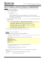
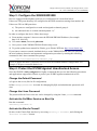
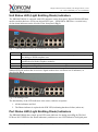
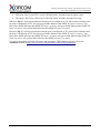
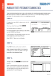
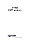
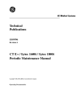
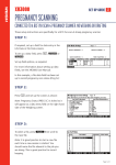
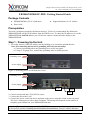
Misgav Industrial Park, POB 60, D.N. Misgav 20174, Israel Tel: +972-4-9951999; Fax: +972-4-9990287 XR2000/XR3000 IP-PBX: Getting Started Guide Package Contents XR2000/XR3000 (2U 19'' width unit) Power cord Support hardware for 19'' cabinet Prerequisites You need a computer equipped with Internet browser. Firefox is recommended. By default, the XR2000/XR3000 will get its IP address from the DHCP server. To check the IP address or to set the XR2000/XR3000 static IP address you will need to connect a keyboard and a display to the XR2000/XR3000. Step 1: Powering Up the Unit 1. For safety reasons, if the line wiring exits the building, it is essential to ground the unit. Note: Not connecting this device to grounding will void your warranty! a. Connect a grounding tab to the grounding screw on the rear panel. b. Using 12-16 gauge wire, connect the grounding tab to a reliable ground. Grounding screw Power Supply Figure 1: Grounding Screw on XR2000 Rear Panel Grounding screw Power Supply Figure 2: Grounding Screw on XR3000 Rear Panel IPMI Eth0 Eth1 2. Connect a keyboard and a VGA/SVGA screen. 3. Connect the unit to the LAN. 4. Connect the power cord to the device and turn on the power using the switch on the rear panel. The device startup process takes about 2 minutes. The startup time depends on the number of telephony ports installed in your XR2000/XR3000 unit. Scan the QR code on the front panel of the IP-PBX for easy access to all relevant product info for this specific product, including detailed technical documentation, “how to” videos, and more. PM0608.04 - XR2000/XR3000 IP-PBX Getting Started Guide (electronic version) Page 1 of 5 Misgav Industrial Park, POB 60, D.N. Misgav 20174, Israel Tel: +972-4-9951999; Fax: +972-4-9990287 Step 2: Configure or Get the IP Settings for XR2000/XR3000 Method 1: If you have a DHCP server: The XR2000/XR3000 will get the IP address from the DHCP server. To get the IP address: 1. Login to the XR2000/XR3000: a. User name: root b. Password: akuo-kfo Note: The default Elastix keyboard configuration is U.S. When entering the password the - (dash/hyphen) key is to the right of the 0 (zero) key, no matter which keyboard layout you are using. 2. To get the IP address use the command: ifconfig eth0 As a result you’ll get a block of data like this: eth0 Link encap:Ethernet HWaddr 00:1C:C0:1F:ED:A0 inet addr:192.168.0.64 Bcast:192.168.0.255 Mask:255.255.255.0 inet6 addr: fe80::21c:c0ff:fe1f:eda0/64 Scope:Link UP BROADCAST RUNNING MULTICAST MTU:1500 Metric:1 RX packets:13221 errors:0 dropped:0 overruns:0 frame:0 TX packets:3658 errors:0 dropped:0 overruns:0 carrier:0 collisions:2129 txqueuelen:1000 RX bytes:5031371 (4.7 MiB) TX bytes:397301 (387.9 KiB) Interrupt:217 Base address:0x2000 In this example the XR2000/XR3000 IP address is 192.168.0.64. Method 2: Set up a static IP address: 1. Login into your system as root, just like in Method 1. 2. Insert the required variables into /etc/sysconfig/network-scripts/ifcfgeth0 : cat > /etc/sysconfig/network-scripts/ifcfg-eth0 <<EOF DEVICE=eth0 BOOTPROTO=static IPADDR=192.168.0.64 NETMASK=255.255.255.0 ONBOOT=yes TYPE=Ethernet EOF 3. Define the default gateway in the /etc/sysconfig/network file: GATEWAY=192.168.0.1 4. Define the DNS server in the /etc/resolv.conf file: nameserver 192.168.0.1 Note: Correct network parameters settings are extremely important for normal PBX functionality. Always make sure that the 'localhost' is defined in the /etc/hosts file: 127.0.0.1 localhost.localdomain localhost PM0608.04 - XR2000/XR3000 IP-PBX Getting Started Guide (electronic version) Page 2 of 5 Misgav Industrial Park, POB 60, D.N. Misgav 20174, Israel Tel: +972-4-9951999; Fax: +972-4-9990287 Step 3: Configure the XR2000/XR3000 Devices equipped with telephony ports are pre-configured as it is described below: If there are FXS ports then they are configured as the PBX extensions starting from number 401. If there are FXO or PRI ports then: a) The ports are configured as a trunk and assigned to channel group 0 b) An outbound route is created with dial pattern “9|.” In order to configure the device follow these steps: a) From another computer’s browser enter the XR2000/XR3000 IP address (for example http://192.168.0.69 ) b) User name admin, Password palosanto c) Now you are in the XR2000/XR3000 Elastix setup screen d) To get the updated user manual for Elastix, go to Elastix WEB site http://www.elastix.org/ If you want to connect external Astribank devices to the XR2000/XR3000, then you can perform the new hardware detection and automatic configuration procedure by running the following command in the Linux command line prompt: /var/lib/asterisk/bin/detect_zap Please be aware that detect_zap utility will overwrite the DAHDI channels configuration. For example, FXS ports extension numbers etc. Step 4: Protect the IP-PBX Against Unauthorized Access Once the IP-PBX is fully configured we highly recommend that you use the following procedures and applications supported in Elastix to protect your IP-PBX against unauthorized access: Change the Default Password a) Login to the server (like for IP configuration) b) Run change-passwords. A wizard for changing MySQL and administrator passwords will start. Change the Linux Password The password for the Linux root user can be changed by using the Linux passwd command. Activate the Fail2Ban Service on Boot Up Run this command: chkconfig fail2ban on Activate the Elastix Firewall Do this via the Elastix Web interface by accessing Security-> Firewall, and clicking the "Activate FireWall" button. PM0608.04 - XR2000/XR3000 IP-PBX Getting Started Guide (electronic version) Page 3 of 5 Misgav Industrial Park, POB 60, D.N. Misgav 20174, Israel Tel: +972-4-9951999; Fax: +972-4-9990287 Unit Status LED (Light Emitting Diode) indicators The XR2000/XR3000 is equipped with LED indicators on the front panel. Digital XR2000/XR3000 models (models that have at least one digital PSTN port – ISDN BRI or PRI) have a vertical array of four status indicators on the left side of the front panel (Fig 3). Fig. 3 – BRI/PRI Panel (allows up to additional 24 FXS ports) LED Label PHONE SYNC ACTIVE ON Indication This yellow LED indicates that the XR2000/XR3000 is supplying the necessary voltage for analog or ISDN telephone sets. This green LED is the synchronization. It blinks once the XR2000/XR3000 is synchronized with the telephony modules. This red LED lights up when at least one PSTN / Analog phone is active. This green LED lights up when the XR2000/XR3000 is powered. XR2000/XR3000 models that do not have digital modules have a different set of indicators, as described in Fig 4: Fig 4. All-Analog Panel The functionality of the LED indicators is the same, with two exceptions: 1. All the indicators are Red. 2. The Phone indicator is replaced with H/W LED, indicating hardware failure (when on). Port Status LED (Light Emitting Diode) Indicators The XR2000/XR3000 has a single green LED status indicator for analog ports (Fig. 4). The Red LEDs are NOT USED for line status indication), and there are two LED indicators for digital ports. PM0608.04 - XR2000/XR3000 IP-PBX Getting Started Guide (electronic version) Page 4 of 5 Misgav Industrial Park, POB 60, D.N. Misgav 20174, Israel Tel: +972-4-9951999; Fax: +972-4-9990287 FXS ports: The Green LED is on for off-hook status. It blinks when the phone rings. FXO ports: The Green LED is on for off-hook status. It blinks when the line rings. BRI port (Fig. 3): Solid green indicates that the port is configured as TE. Solid yellow indicates that the port is configured as NT. Two fast green blinks Indicates that ISDN TE layer 1 is active. Two fast yellow blinks Indicates that ISDN NT layer 1 is active. One green blink indicates that ISDN TE layer 2 is active. One yellow blink indicates that ISDN NT layer 2 is active. PRI port (Fig. 3): Solid green indicates that the port is configured as TE. Solid yellow indicates that the port is configured as NT. Two fast green blinks Indicates that ISDN TE layer 1 is active. Two fast yellow blinks Indicates that ISDN NT layer 1 is active. One green blink indicates that ISDN TE layer 2 is active. One yellow blink indicates that ISDN NT layer 2 is active. For more information about the unit status and port status LED indicators please refer to the Astribank manual at http://www.xorcom.com/astribank-technical-documentation. PM0608.04 - XR2000/XR3000 IP-PBX Getting Started Guide (electronic version) Page 5 of 5