1
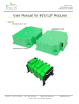
IOXUS, INC. 18 Stadium Circle Oneonta, NY 13820 User Manual for 48V/165F Modules Models: Industry Standard footprint o iMOD048V165-XXA Table of Contents Models: ................................................................................................................ 1 Introduction ........................................................................................................ 2 Module Part Numbering and it’s Meaning ............................................................ 3 Handling .............................................................................................................. 3 Unpacking .................................................................................................................. 3 Handling .................................................................................................................... 3 Installation .......................................................................................................... 4 Orientation and Application ........................................................................................... 4 Environment ............................................................................................................... 4 Venting ...................................................................................................................... 5 Monitoring .................................................................................................................. 6 Balancing ................................................................................................................... 8 Safety .................................................................................................................. 9 Discharging .................................................................................................................. 10 Accessories ....................................................................................................... 10 Operation .......................................................................................................... 11 Maintenance ...................................................................................................... 11 Reconditioning ............................................................................................................. 11 Storage.............................................................................................................. 11 Disposal............................................................................................................. 11 Toll Free: +1 877-751-4222 Fax: 607-433-9014 http://www.ioxus.com © 2013 Ioxus, Inc. All rights reserved. [email protected] IOXUS, INC. 18 Stadium Circle Oneonta, NY 13820 Never touch the power terminals as any residual voltage can cause fatal electrical shocks, Always check with a calibrated meter that the module is discharged prior to handling the module, please see the step by step instructions in this manual for the discharge procedure. Warranty Limitation Ioxus modules are unserviceable property of the customer and if opened or otherwise modified, are no longer covered by any warranty written or implied Introduction Ioxus modules represented in this document are designed for a wide variety of applications from stationary back up power to transportation usage. Each module is built with welded bus bars and internal balancing circuitry. The balancing circuitry can be one of several formats based on the options selected. The standard balancing circuitry for the large format modules is a 2-stage active balancing that will be described later in the document. The balancing circuitry is built in and protected by the aluminum housing allowing the entire structure to be rugged and also meet the water resistance requirements of IEC 60529 – IP65. The specifications and recommended configurations suggested in this manual are subject to change and should be verified by checking the most recent version of this document and the product datasheets on www.IOXUS.com. Please keep note of your model number when referencing this manual and note if each section refers to your specific model number. If your model has an output connector, specifications for that connector and how to use each connection will be detailed in the appropriate sections below. Toll Free: +1 877-751-4222 Fax: 607-433-9014 http://www.ioxus.com © 2013 Ioxus, Inc. All rights reserved. [email protected] IOXUS, INC. 18 Stadium Circle Oneonta, NY 13820 Module Part Numbering and it’s Meaning Handling Unpacking Please inspect the shipping carton for signs of damage prior to unpacking the carton. Report any damage to the carton, or the contents, to the carrier immediately. Retain all shipping materials until the module is fully inspected and determined to be operational. The module should be lifted by the module body. The terminals should not used for hoisting. The terminal shorting wire should remain in place. If any parts are determined to be missing or defective an RMA number must be issued prior to returning the unit for repair or replacement. Please contact your salesperson or distributor to request an RMA number. Handling Ultracapacitor modules are designed for years of maintenance free operation if handled, installed and used properly. These handling precautions should be observed. The modules should not be stacked unless still in original packaging The only tools to be used on the module should be properly sized wrenches for the terminal and mounting bolts (hammers, chisels, files or power tools in general should not be used) Do not drop modules, invisible internal damage may occur Toll Free: +1 877-751-4222 Fax: 607-433-9014 http://www.ioxus.com © 2013 Ioxus, Inc. All rights reserved. [email protected] IOXUS, INC. 18 Stadium Circle Oneonta, NY 13820 Installation Orientation and Application 48V modules can be mounted in any orientation and are qualified for shock and vibration as is detailed on the applicable datasheet. Please review the datasheet and test specifications to determine the appropriateness of the module for your application. The modules should not be mounted anywhere where the frame member mounted to applies any stress torque or twisting to the module housing. All mounting holes are located on the end plates, and should be mounted to points that are in plane with each other (or parallel to each other for Rack mount applications). Shims and spacers should be used if any of the mounting points are more than ±1mm out of plane. 8mm hardware of a grade appropriate for the application should be used for standard 48V modules. In addition it is best to avoid mounting on or near significant heat sources such as engine exhausts or solar heated panels Environment For best results modules should not be exposed directly to the environment, particularly the avoidance of direct splashes should be considered. In systems with voltages greater than 60V, protection of the terminals to avoid shock and corrosion should be instituted. Modules that are expected to see significant cycling should be mounted in free air or in forced ventilation housing. Care should be taken to protect modules in potentially corrosive environments and direct water splash or spray is should be avoided. In all environments the best possible performance is aided by using an anti-oxidation agent on the aluminum terminals. No-Al-Ox or other similar products are appropriate and highly recommended for all terminal connections. Toll Free: +1 877-751-4222 Fax: 607-433-9014 http://www.ioxus.com © 2013 Ioxus, Inc. All rights reserved. [email protected] IOXUS, INC. 18 Stadium Circle Oneonta, NY 13820 Careful design consideration should be given to the application to prevent the overheating of the modules. Temperature monitoring is optionally available and discussed later in this document. Please refer to the operational temperature range on the data sheet and be sure to allow for internal heating of the modules. If you require help with the design considerations and sizing please contact your representative for assistance. Vent Hole Mounting Feet for M8 Bolts (4X) Venting Please note a venting hole is built into each module and a filler bolt is fitted to it. If external venting is required remove the M5 bolt and fit with appropriate plumbing to relocate the vent. Electrical Modules can be mounted in series and/or parallel with each other. Care should be taken to insure that similar capacitance and ESR modules are used for series chains and that if different type or age modules are used in parallel configurations the differences in ESR are accounted for in your design. Appropriate size bus bars or cables and terminals should be used for the application. Please note, that to minimize system loses the capacitors do not have fusing or internal circuit breakers, careful consideration in the system design should be taken to prevent over current. With the low ESR of the capacitors they can deliver very large amounts of current. Toll Free: +1 877-751-4222 Fax: 607-433-9014 http://www.ioxus.com © 2013 Ioxus, Inc. All rights reserved. [email protected] IOXUS, INC. 18 Stadium Circle Oneonta, NY 13820 A grounding strap should be installed on each module. The worst-case fault current should be considered when sizing the wire for this application. It is recommended to remove the anodizing or coating (if applied) on the housing at one of the bolting points to allow for the ground strap to be properly installed. Thread locking should be done with a split ring and flat washer combination as is provided with the modules or an appropriate chemical thread locker applied only to the threaded portion of the terminal/bolt. The terminals are 8mm and 10mm (positive and negative). They should be torqued to 15-20Nm for the positive and 18-30Nm for the negative. Care should be taken to not over torque the terminal bolts and re-torqueing is not recommended. Additionally, bolts chosen should be at least 10mm but not exceed 18mm of remaining exposed thread to be installed in the terminal (considering the fully compressed installation height of all the attached terminals and washers applied). Care should be taken in cable routing to not impose undue forces (torques or tensions) on the module terminals. Only appropriately sized ring terminals or bus bars for the expected currents should be used. Series Connections Parallel Connections Monitoring There are 2 types of available monitoring configurations noted by the suffix on the part number for your module(s). Suffix -01X is the common part number, if -02A is required additional lead time will be required 1. -01X - Digital overvoltage caution, analog temperature monitoring 2. -02X - Digital overvoltage caution, digital over temperature caution Toll Free: +1 877-751-4222 Fax: 607-433-9014 http://www.ioxus.com © 2013 Ioxus, Inc. All rights reserved. [email protected] IOXUS, INC. 18 Stadium Circle Oneonta, NY 13820 Common specifications For both -01X and -02X o Operating Voltage 5-24V Max 80V o Overvoltage output: Digital- open collector Trigger if any group of 3 cells exceeds 8.25V (2.75V/cell) o Max operating current o 3mA o MFG part number for mating connector AMP 1445390-3 Shell size=8 Contacts=4 o Pin out Diagram Digital Outputs are continuously parallel-able, they can be paralleled across parallel and series module connections. -01X Digital Overvoltage, Analog Temperature Temperature output: Analog Thermistor o US Sensors 103E1G1K Base resistance 10kΩ @ 25°C Pin out as follows: Pin1: Optical Collector (VC) Pin2: Optical Emitter (SG) Pin3: NTC (TH1) Pin4: NTC (TH2) o Generalized Schematic o Toll Free: +1 877-751-4222 Fax: 607-433-9014 http://www.ioxus.com © 2013 Ioxus, Inc. All rights reserved. [email protected] IOXUS, INC. 18 Stadium Circle Oneonta, NY 13820 -02X Digital overvoltage and over-temperature o Pin Configuration o Pin 1- overvoltage collector o Pin 2- overvoltage emitter o Pin 3- over temperature collector o Pin 4- over temperature emitter o Over temperature caution triggered when the sensor measure greater than 60C internal module temperature o 2 monitoring output connectors are fully parallel, no priority Balancing The standard balancing for the large format modules is a 2 stage balancing that employs a lowlevel equalization resistor that operates when the cell is above 2.15 V. Each cell is individually monitored and from rated voltage the maximum time to convergence (@ 2.15V is 11 hours). This circuit deactivates when the cell reaches 2.05V there is also a second stage that is much more aggressive and triggers if any 3 cell group exceeds 8.25V (2.75V/cell). This will rapidly bring that group back down into the rated voltage range and deactivate at 2.70V/cell. The basic balancing function is demonstrated in the following chart. Toll Free: +1 877-751-4222 Fax: 607-433-9014 http://www.ioxus.com © 2013 Ioxus, Inc. All rights reserved. [email protected] IOXUS, INC. 18 Stadium Circle Oneonta, NY 13820 Safety Never touch the power terminals as any residual voltage can cause fatal electrical shocks, Always check with a calibrated meter that the module is discharged prior to handling the module, please see the step by step instructions in this manual for the discharge procedure. Prior to installation or removal the module and or system of modules must be discharged fully and shorting wires installed (procedure below) Provide sufficient electrical isolation for operation above 50VDC Protect surrounding electrical and conductive components from incidental contact Do not operate above specified voltage or temperature range Do not touch terminals while charged, serious burns, shock or material fusing may occur Toll Free: +1 877-751-4222 Fax: 607-433-9014 http://www.ioxus.com © 2013 Ioxus, Inc. All rights reserved. [email protected] IOXUS, INC. 18 Stadium Circle Oneonta, NY 13820 Discharging A fully discharged module may “bounce back” if it is stored without a shorting wire connected to the + and – terminals. This bounce back can be as much as 6V for the 48V module, and is enough to cause dangerous electrical shocks and other undesirable consequences. Prior to any maintenance or replacement each module should be individually discharged and shorted with a resistor or wire. Even a fully discharged module can rebound naturally to an unsafe condition. Be sure to discharge with an appropriately sized resistor or resistor bank (not provided) and either keep that resistor attached or replace it with a shorting wire or bus bar when the module is depleted. Be sure to check the voltage with a calibrated meter prior to attaching the shorting device. The voltage should be 0±0.25V. 1. Using a voltmeter, measure the voltage between the 2 terminals. 2. If the voltage is above 2V, a resistor pack (not supplied with the module) will need to be connected between the terminals. Proper care needs to be taken in the design and construction of such a dissipative pack. e.g. At 48V, for a 4 Ohm pack, the module will be initially discharged with a current of 15A and will take about 15 minutes to fully discharge. However, in this case, the heat/power dissipated in the resistor pack will be ~ 1.2kW. The resistor pack will need to be sized and provided with suitable cooling to handle this power dissipation. Additionally, proper enclosure or other packaging is necessary to ensure safety. In all cases, proper design of the dissipative resistor pack is necessary. 3. If the voltage is under 2V, connect the shorting wire provided by Ioxus to the + and – connectors. 4. The module is now safe for handling. Leave the shorting wire connected at all times. Accessories Module accessories such as mating connectors and terminal hardware are available for order. Custom cables, bus bars and monitoring connections are available on request but may require an NRE charge and will require all relevant mounting considerations in order to design your product. Please contact your Ioxus representative with questions or requests. Toll Free: +1 877-751-4222 Fax: 607-433-9014 http://www.ioxus.com © 2013 Ioxus, Inc. All rights reserved. [email protected] IOXUS, INC. 18 Stadium Circle Oneonta, NY 13820 Operation All modules should only be operated within their prescribed voltage, constant current and temperature, operating window. These should be monitored to ensure the safe operation and long life of your module. NOTE: Operation of module above 65C will void the warranty Maintenance The modules should be kept free of dust and debris and cleaned at a regular interval. In inside locations, that should be no more than annually however this may vary with your particular circumstances. Outside location will be as needed. Once the modules are discharged, proceed with cleaning with a cloth and a simple water/soap solution. Avoid the use of hoses or pressurized sprays. Once the assembly is clean check for properly torqued fasteners and note any damage to any of the housings or signs of internal damage and replace as necessary. In high vibration applications fasteners used for mounting as well as electrical connections should be checked for torque every 6 months. Reconditioning This module does not require condition because of the 2 stages of balancing. Storage The module can be stored in the original package discharged in a dry place. Observe the maximum storage temperature as stated in the specifications. Discharge used module prior to stock or shipment. The shorting wire shipped with the unit should be retained for use during storage to prevent charge from accumulating in the module. Disposal Please recycle according to local codes and regulations for flammable materials. Toll Free: +1 877-751-4222 Fax: 607-433-9014 http://www.ioxus.com © 2013 Ioxus, Inc. All rights reserved. [email protected]