1
Keypad
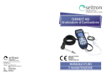
Silicone rubber keypad featuring main control functions (pos. A in Fig. 2.2).
1
Display
Backlit 128 x 64 pixel LCD display (pos. B in Fig. 2.2), with 8 lines x 20 characters available. Allows the user to
view the measured parameters in the most comfortable format; a Zoom function displays the measured values in
magnified form.
CAUTION: If the instrument is exposed to extremely high or extremely low temperatures, the quality of
the display may be temporarily impaired. Display appearance may be improved by acting on the contrast
key.
2
Rechargeable Battery Pack
The instrument is provided with a 12VDC, 2A power supply pack to charge the internal batteries.
The socket for connecting the battery charger to the instrument is shown as item M in Fig. 2.2. Once the charge
is started the display turns on and shows the charge status.
Serial connector (Mini Din 8-pole)
In N of Fig.2.2 we find the socket of the serial cable for connecting the instrument to an external probe, for
example, to the draft gauge (optional), or to the ionization current probe (optional).
3
Mini/USB connector
In O of Fig.2.2 we find the socket of the serial cable for connecting the instrument to a personal computer.
Sample pump
The sample pump located inside the instrument is a DC-motor-driven diaphragm pump, powered by the
instrument, and is such as to obtain optimal flow of the sampled gas being analyzed.
Flue Gas Sampling Probe
Stainless steel probe with plastic handgrip (see C of Fig.2.2). The Standard Length of the steel probes is 12
inches (300 mm). Other available lengths are 180 mm, 750 mm and 1000 mm with adapter cone for the flue
hole, diameter 8-22 mm. A flexible probe is also available with a 300 mm long tip, for measuring inside flues
where the fumes picking point is difficult to reach. All probes have a nominal outside diameter of 8 mm.
Connection to an analyzer via a 3-meter rubber hose and replaceable condensate separator and fine dust filter
unit (see D of Fig.2.2).
Measurement Cells
The instrument uses pre-calibrated gas sensors of the long-lasting FLEX-Sensor series for measuring oxygen (O2)
and carbon monoxide CO. Up to 4 alarms can be programmed with visual and acoustic warning for the same
number of measuring parameters.
The measuring cells are the electrochemical type. The UNI 10389-1 standard prescribes that the instrument must
be calibrated once a year by an authorized laboratory to issue calibration certificates. When the cells are flat they
can be replaced easily by the user without having to send the instrument away and without complicated
calibration procedures requiring sample mixtures as they are supplied already calibrated.
E Instruments does, however, certify measurement accuracy only when a calibration certificate has been issued
by its own laboratory or by an authorized laboratory.
Temperature sensors
Flue gas temperature is measured by means of a thermocouple inserted in the tip of the probe.
The thermocouple is connected to the instrument via a compensated cable (pos. E in Fig. 2.2.) housed in a
special seating in the rubber hose of the sample probe.
Connection to the instrument is achieved via a temperature-compensated male connector.
The cold junction is compensated by a Pt 100 resistance thermometer which measures the temperature at the
thermocouple connector.
The type K thermocouple (nickel/nickel chromium) permits continuous measurements up to 800°C. If speci alpurpose probes are used, the instrument is able to measure temperatures as high as 999.9°C.
A Pt 100 resistance thermometer located inside the instrument measures the internal temperature; this sensor is
also used to measure the ambient temperature.
Should the user want to measure the combustion air temperature directly in the intake duct, the optional remote
Pt 100 sensor must be used - this measurement is recommended for more precise calculation of plant efficiency.
Remote temperature probe
The temperature probe consist s of a Pt 100 probe, complete with 2 m cable and 7.5/17 mm pit adapter (pos. F
K8000 000 00EJ 02 102 0A0 25 071 2
9
4
5
6
7
8