1
Rev. B.2
$ 5.00
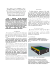
EKT-1016
Arduino 16-Channel Power Driver
User's Manual
ElectronicKit.com
ElectronicKit.com
(818)783-4299
Copyright
Copyright (c) 2013 by ElectronicKit.com. All rights reserved. No part of this publication
may be reproduced, transmitted, transcribed, stored in a retrieval system, or translated into any
language or computer language, in any form or by any means, electronic, mechanical, magnetic,
optical, chemical, manual or otherwise, without the prior written permission of ElectronicKit.com,
a subsidiary of the Antona Corporation, in Los Angeles California.
Warranty
ElectronicKit.com built products are warranted to be free from defects in materials and
workmanship for a period of one (1) year from the date of original shipment to the customer. We
can not offer any warranty coverage for user built or modified products purchased from us.
This warranty is limited to the replacement or repair of parts not subjected to misuse,
neglect, unauthorized repair, alteration (except card options), accident, or failure due to the
effects of static electricity discharge.
By using our products, the customer acknowledges that our equipment is not commercial
grade or industrial qualified. The EKT series PCBs are for use by hobbyist, experimenters,
instructors and engineers for entertainment, learning, demonstration and prototypes/proof-ofconcept applications. The designer is cautioned not use these products for any end-user
systems for resale.
In no event shall ElectronicKit.com be liable to the purchaser for loss of use, profit, or
consequential damages, or damages of any kind, including, but not limited to, accidental loss or
damage to other equipment, arising out of use of ElectronicKit.com equipment, whether or not
said equipment was used properly. The designer is responsible for the determining the
suitability and use of the product.
This warranty is in lieu of any other warranty, expressed, implied, or statutory, including,
without limitation, any implied warranty or merchantability or fitness for a particular purpose. No
amendment of this warranty may be effected except in writing by an officer of the
ElectronicKit.com.
All repair services shall be performed at the ElectronicKit.com plant in Los Angeles,
Ca. THE PURCHASER MUST OBTAIN A RETURN AUTHORIZATION FROM THE
ELECTRONICKIT.COM PRIOR TO RETURNING ANY PIECE OF EQUIPMENT.
Shipment to ElectronicKit.com will be at the expense of the purchaser, return shipment
will be at the expense of the ElectronicKit.com for all warranty repairs.
ElectronicKit.com
1
TABLE OF CONTENTS
FEATURES.....................................................................................................................................................................................3
OVERVIEW....................................................................................................................................................................................3
Fig 1 – Basic EKT-1016 System............................................................................................................................................................3
MECHANICAL SPECIFICATIONS.........................................................................................................................................................4
ELECTRICAL SPECIFICATIONS...........................................................................................................................................................4
CARD INSTALLATION.......................................................................................................................................................................4
SHIELD POWERING.........................................................................................................................................................................4
EXTERNAL POWERING.....................................................................................................................................................................5
SHIELD CONTROL...........................................................................................................................................................................5
SHIELD JUMPER OPTIONS.......................................................................................................................................................6
Fig 2 - EKT-1016 jumper locations set as shipped.................................................................................................................................6
DRIVER ENABLE - JP1...................................................................................................................................................................7
Fig 3 – Driver Enable Jumper................................................................................................................................................................7
Card Driver Enable – JP1........................................................................................................................................................7
I2C ADDRESS AND SOURCE SELECT - JP2.......................................................................................................................................8
Fig 4 – I2C Addr and Source................................................................................................................................................................. 8
I2C Address Jumpers................................................................................................................................................................8
Card Address – JP2/ADR.........................................................................................................................................................8
I2C Source Jumpers..................................................................................................................................................................9
Fig 5 – Pull up Resistor D and C Jumpers..............................................................................................................................................9
I2C PULL UP ENABLE – JP ‘D’ AND ‘C’ ........................................................................................................................................9
CONNECTING DEVICES TO THE DRIVERS.......................................................................................................................10
Fig 6 – Attaching a device for card control...........................................................................................................................................10
TERMINAL BLOCK DEVICE CONNECTION........................................................................................................................................11
Fig 7 - Driver terminal blocks and TB2 Aux power block....................................................................................................................11
Port A - TB3 and PA connections .........................................................................................................................................11
Port B – TB1 and PB connections .........................................................................................................................................11
Auxiliary +V DC Inputs for Port A and B..............................................................................................................................11
PROGRAMMING THE EKT-1016............................................................................................................................................13
BEGINNING OF SKETCH:.................................................................................................................................................................13
‘SETUP’ SEGMENT:........................................................................................................................................................................13
ENABLE/DISABLE DRIVERS:............................................................................................................................................................14
WRITE DATA TO PORT A AND B:....................................................................................................................................................14
COMPLETE EKT-1016 SKETCH – RIPPLE1016.INO.........................................................................................................................14
APPENDIX A – EKT-1016 TROUBLESHOOTING GUIDE.................................................................................................17
Driver Channel Problems:.....................................................................................................................................................17
LED Test.............................................................................................................................................................................................. 17
Wiring or Cabling (a common problem) ..............................................................................................................................................17
Over Current......................................................................................................................................................................................... 17
Overall Shield Operation:......................................................................................................................................................17
Signal Control Jumpers......................................................................................................................................................................... 17
I2C Signal Termination........................................................................................................................................................................ 18
Powering............................................................................................................................................................................................... 18
Program Operation............................................................................................................................................................................... 18
Now What?........................................................................................................................................................................................... 18
APPENDIX B – USER INSTALLED STATUS LEDS.............................................................................................................19
Fig 8 LED Test Fixture......................................................................................................................................................................... 19
APPENDIX C - KIT ASSEMBLY..............................................................................................................................................20
APPENDIX D EKT-1016 SCHEMATICS...............................................................................................................................25
APPENDIX E ASSEMBLY DRAWINGS (FULL AND SMD ONLY)..................................................................................27
ElectronicKit.com
2
Features
16 Channels of Digital Power Output (1 Amp continuous)*
External power driver source from 5 to 36 volts
RoHS Compliant – Lead Free parts and construction
Designed and Made in the USA – both PCB and Assembly
Easy terminal block interfacing with discrete wires
Uses I2C for card control – Only 2 Arduino data signals required
Programs using the 'WIRE' library in the Arduino IDE - sample code on website
Multi-card operation – card select jumpers and stackable Arduino connectors
Compatible with Arduino UNO Duemilanove, UNO R3 Leonardo and 100% Arduino clone
cards
Surface mount technology (SMT) and socketed power drivers
Software output driver disable option for lower stand by power
Solder pads for external Schottky blocking diodes (added power dissipation) or for user
supplied status LEDs (see Appendix B)
*NOTE: There is a continuous current limit of 6 Amps for the PCB - that is due to the trace width and
individual driver IC wattage limitations. User should determine current use and design accordingly.
Additional heat sinking and/or a fan would be recommended for continuous high current operation.
Overview
The EKT-1016 shield gives the Arduino system designer 16-pins of digital power driving
capability. There are enough output pins to drive 4 stepper motors (unipolar or H-bridge), 16
power LED strings or 16 relays to sequence electric sprinkler valves for an Arduino based
gardening system. Each driver can handle 1 Ampere of current, but each power driver
chip supplying 4 channels, has a 2 watt maximum power dissipation.
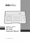
Fig 1 – Basic EKT-1016 System
An application example would be where one EKT-1016 plugged into an Arduino UNO
inside of an office remotely turns 2 stepper motors via port A connected to worm gears that tilt
and/or pan a small roof mounted solar array to follow the Sun for maximum energy generation.
Aiming would be performed either by time-of-day (and day-of-year), or by measuring power
output and adjusting for maximum signal input to analog input pin(s). Port B, externally powered
ElectronicKit.com
3
from the batteries charged by the solar array during the day, could be used to drive LED lighting
in the evening. By monitoring battery voltage (again, through an analog input line on the
Arduino) the user’s sketch could turn off LEDs as needed by control of ports B’s 8 channels.
As for terminology, several references are made to ‘card / add-on card’ and ‘program’
which are commonly referred to as ‘shield’ and ‘sketch’ respectively in Arduino parlance. There
is some information repeated under the various sub headings of the manual. This is handy for
the user who just wants to quickly get into using the card without reading the whole manual.
The author has found that repeating information reinforces the important points and insures the
designer will have a better chance of reading a warning, tip or application at least once while
going through the manual. The manual represents the authors attempt to cover the shield’s
detailed operation in the hope that it will save time and reduce the learning curve to apply the
EKT-1016. Important information like warnings and limitations are highlighted by being
in bold, italic and underlined (like this).
Mechanical Specifications
Shield size:
2.9" X 2.6" (74mm x 66mm)
Connectors:
2 – 10-pin Terminal Blocks for port A/B output
2 – Sets of 10 solder pads for 0.1” (.254mm) pins for A/B output
4-pin Aux. Terminal Block for external driver voltage input
Standard stacking connectors for Arduino interfacing
Electrical Specifications
Power requirements = +5v @ 30 ma
(Arduino is power source)
External Voltage(s) =
+5v to +36v DC at 6 Amps MAX (depends upon user application)
Card Installation
Turn off power to the Arduino and any other attached equipment before performing the
shield installation. Never install or remove the EKT-1016 with the power applied to the
Arduino or any of the attached equipment. This could result in permanent damage to the
card due to static discharge.
Normally the shield is plugged directly into the circuit side Arduino bus connectors. The
user should use standoffs from the Arduino to the EKT-1016 for permanent installations to
assure good long-term connection and added heat sinking.
Shield Powering
The power for the ElectronicKit.com shield is from +5V and GND on the Arduino PW/J4
connector (see page 2 of the schematic). Average current used by the shield is xxx ma.
Remember, to power the attached equipment to the EKT-1016, the user must attach an
external source of DC voltage. The Arduino regulator can not supply enough current for
power driving applications. That is why there are no jumpers for the user to connect the
Arduino power +5v to power drivers even though that might be handy for testing – the user could
easily forget to remove such a jumper, connect an external power supply to the output port
terminal block and burn up the Arduino card.
ElectronicKit.com
4
External Powering
The Arduino can NOT provide enough current through its on-board voltage regulator to
drive much power for 16-channels of output. That is why there are terminal block pins, IDC pins
and even a separate 4-pin terminal block to ensure the user can apply an external DC voltage
with enough current to drive the outputs. Do not wire up the +5v from the Arduino to power
the output drivers unless you are sure of what you are doing. An external +5 to +36 voltage
source may be feed into pin 1 of the port A (TB3) or B (TB1) 10-pin terminal block. The ground
return from the external power supply should be connected to pin 10 of the respective port
terminal block.
Additionally, there are 2 groups of 10 solder pads that line up behind TB1 and TB3 for the
user to use when SIP connectors or soldered connections are desired to the power driver
outputs. Each pad follows the pin function of the terminal block in front of it. These pad rows also
can be used for adding external Shockley blocking diodes to increase card power dissipation or
even adding LEDs for status of each driver.
The designer can also use pins 2 and 4 of the 4-pin terminal block (TB2) for powering port
A and B respectively. Why? Because the user may want to use a peripheral board which needs
powering, and using TB2 to supply power allows taking power from pin 1 on each port terminal
block.
You can have 2 different voltages on the EKT-1016 card. Meaning you could run port A
with +12v DC, and port B with a +9v DC source. See figure 1 below for the terminal block
pinouts.
Provide external power to ONLY one of the 3 possible single port powering pins.
This means to power port A, use either pin 1 of the TB3, or pin 1 of the PA IDC pad or pin 4 of
TB2 and for power to port B, use either pin 1 of TB1, or pin 1 or PB or pin 2 of TB2. For
advanced users, you could diode isolate 2 sources of DC voltage to provide a backup supply for
operation.
Shield Control
The ‘reset’ signal on the EKT-1016 is drawn from the Arduino PW/J4 connector (see page
2 of the schematic). Along with ‘reset’, ‘SDA’ and ‘SCL’ are used for I2C control (see page 2 on
the schematic for physical pin location). Optionally, the user can use one additional digital line
for enabling the power output drivers, or choosing to enable the drivers always (as shipped).
The designer can jumper select any one of D2, D3, D7, or D8 for driver enabling by program
control. Sample 'C++' code is listed under the “Programming the EKT-1016” heading below to
show how sketches can enable and disable the drivers as required.
ElectronicKit.com
5
Shield Jumper Options
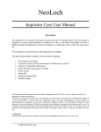
Fig 2 - EKT-1016 jumper locations set as shipped
When shipped, the EKT-1016 is set for:
Power drivers enabled always
I2C device address set to 0 (00H-1F hex range)
I2C control lines on pins 5 and 6 of J1(works for UNO and R3)
SDA/SCL pull up resistors enabled
All references to ‘horizontal’ and ‘vertical’ below are in respect to figure 2 above.
The Appendix D schematic, gives another view of the jumpers showing the settings by
their physical electronic function.
Easiest to work on the card while it is mounted on top of the Arduino stack and
unpowered. This makes testing the shield easy while jumper changes are being made.
Avoid the temptation of changing jumpers while the card is powered!
ElectronicKit.com
6
Driver Enable - JP1
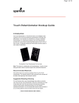
Fig 3 – Driver Enable Jumper
The EKT-1016 can be output controlled by selecting one of four data lines, or the driver’s
can be enabled always (as shipped, by setting JP1 to Ground – the G position jumper). On
power up or reset, the data lines on the Arduino CPU are set to input, R1 pulls up the gate
inputs to U5 and that disables the output drivers of the shield. Now the user’s sketch can
initialize the card’s control and preset the data bytes BEFORE enabling the drivers. That insures
a consistent start up and helps prevent all 16 drivers from coming on at once – which could be
bad depending upon the application. In addition, the program can also disable the driver output
pins to lower power used and reduce system heat. A single jumper is used for this option, but
multiple EKT-1016 could have different settings. Why disable the drivers under software
control? If you needed to do an initial position setting of a worm gear attached to a stepper
motor, disabling the stepper motor power would allow turning the motor by hand. Remember,
controlling the driver output can significantly lower the current used and heat generated
by the card. Only one data bit can be selected, but separate shields can use different
enable data lines if desired. The table below details the setting options by data bit:
Card Driver Enable – JP1
Signal
Function
D8
D7
D3
D2
GND
Data bit 8
Data bit 7
Data bit 3
Data bit 2
Ground
Jumper Pin
8
7
3
2
G
Comment
uses PB0 for control
uses PD7
uses PD3
uses PD2
Always on (as shipped)
Note also that the user could use the G jumper pair for wiring an external collection of (seriesconnected) normally-closed limit switches. In this way when a limit switch is opened, all power
to the drivers would be disconnected.
ElectronicKit.com
7
I2C Address and Source Select - JP2
Fig 4 – I2C Addr and Source
I2C Address Jumpers
Jumper 2, located on the lower left hand side of the PCB, is really two sets of 6-pins
combined into one 12-pin jumper. The right hand set of 6-pins sets the shield software address
and the left hand 6-pins set the I2C signal source.
The 3 right hand shunts set the A0, A1 and A2 address (labeled 0 1 2 in figure 4 above)
that the card will answer to on the I2C bus. When shipped, all 3 shunts are shorted across the
pair of pins to produce a ‘0’ (LOW) address bit, producing address x00H (00 hex). Opening a
shunt by removing it will produce a ‘1’ (HIGH) to the corresponding address bit. The table below
details the address combinations:
Card Address – JP2/ADR
Card Adr
Adr Range
(hex)
0
1
2
Comment
0
1
2
3
4
5
6
7
00-1F
20-3F
40-5F
60-7F
80-9F
A0-BF
C0-DF
E0-FF
LOW
HIGH
LOW
HIGH
LOW
HIGH
LOW
HIGH
LOW
LOW
HIGH
HIGH
LOW
LOW
HIGH
HIGH
LOW
LOW
LOW
LOW
HIGH
HIGH
HIGH
HIGH
As shipped
Each setting covers 32 (1F hex) addresses. For the EKT-1016 card only 4 addresses per
setting is used. The other addresses can not be safely used by other I2C cards, but there
should be no problem with an address conflict even if four EKT-1016 shields were stacked on a
single UNO/R3 card. There are 2 address settings that the user should be aware of: 0 (00-1F
hex) and 7 (E0-FF hex). For most EKT-1016 applications, it will not be a problem but there are
'reserved' addresses within those two address ranges.
addr R/W Description
0000 000 0 General call address
0000 000 1 START byte
0000 001 X CBUS address
0000 010 X Reserved for different bus format
ElectronicKit.com
8
0000 011 X
0000 1XX X
Reserved for future purposes
Hs-mode master code
1111 1XX X
1111 0XX X
Reserved for future purposes
10-bit slave addressing
The author has run the EKT-1016 using the Arduino IDE's 'WIRE' library with both 0 and 7
without a problem. Running other libraries that generate I2C communication may have a
different result.
I2C Source Jumpers
The left most 6-pins of JP2 are used to select the source of the I2C data (fig 4 above).
The jumper pairs on JP2, located at the lower right hand side of the PCB, allow the designer to
swap the I2C SDA and SCL source. A change was made to the Arduino R3 hardware that
dedicates two I2C pins located on J2 of the Arduino expansion connector. This jumper option
handles any future issues of I2C compatibility by allowing the user to select the dedicated I2C
pins and free up A4 and A5 on J1 for other uses. When shipped, the I2C source is the
original A4/SDA and A5/SCL pins of the Arduino UNO. That is, both horizontal pins are
plugged into the center and left pin of the jumper set (U on silkscreen fig 4). The designer
should change both jumpers from center pin to right pin if it is desired to use the newer pins
located on J2 (R on silkscreen fig 4). This feature is probably not to useful on the EKT-1016
with the Arduino R3 or UNO as both sources of SDA and SCL are the same on those
Arduino CPU cards. This choice of I2C sources may be useful on future Arduino CPU
card versions.
Fig 5 – Pull up Resistor D and C Jumpers
I2C Pull up Enable – JP ‘D’ and ‘C’
If the user is stacking multiple shields onto the Arduino expansion connectors that make
use of the I2C interface, these two jumpers, designated D (data) and C (clock) and located
above the JP2 jumper, should be disconnected on all but the topmost shield on the stack.
Multiple pull up resistors may work (especially if it is only 2 cards), but for the best signal, only
one pair of resistors should be enabled. The user should carefully cut the small trace running
between the 2 pads located near the ‘D’ and ‘C’ silkscreen letters located on the solder side
(back) of the PCB.
ElectronicKit.com
9
Connecting Devices to the Drivers
Attaching devices to the EKT-1016 is straightforward if the user understands the drivers
operate by pulling their output to ground. This means one end of the attached device (see
the figure below for examples) is connected to an appropriate +voltage for operation while the
other device lead is attached to a shield terminal block driver pin. There are a few exceptions,
but for a majority of applications, that is the only correct (or workable) technique for
operation. The user also needs to connect the external power source to the port on pin 1 for
proper operation. Wire the external power supply ground to pin 10 (see fig 6 and 7 below).
The EKT-1016 is for applications with medium power digital devices. That means the
usual output control limitation of 40ma from the Arduino digital pins can now be up to 1 Amp.
Medium power stepper motors, high power LEDs, relays, etc. can be easily handled by this
shield. There are limits of what the user can do as the circuit board traces and terminal
blocks (plus common sense) limit the card to 6 Amperes running concurrently. That is a
lot of current, but the user should still be aware of what is being controlled and the current the 16
channels are drawing with all outputs on. The EKT-1016 can run 4 stepper motors at the same
time because not all of the outputs are running at the same time. 4 motors might mean as many
as 8 channels on at the same time so the user would have to 1 - make sure the motor is not
drawing more then about 750 ma per lead and 2 – that air is being moved over the PCB to cool
the driver chips. The user could run 16 high power LED strings at the same time with 375 ma
per channel.
Fig 6 – Attaching a device for card control
The schematic in figure 6 above shows 3 different types of devices being controlled by
the EKT-1016. Note that all 3 example device types are being powered by the same +12V
external power supply (and ground return). Attach an additional wire from the external +V to pin
1 (VAX or VBX) of the terminal block being used. In addition, connect a wire from the external
power supply to the ground to pin 10 of the port being used. Only one external voltage per port
can be accommodated, but you can ‘match’ a device (like the power LEDs above) with a load
resistor, zener diode, LDO, etc. if need be. Most of the time you will be connecting devices of the
same voltage up to the individual port(s).
ElectronicKit.com
10
Terminal Block Device Connection
Fig 7 - Driver terminal blocks and TB2 Aux power block
Port A - TB3 and PA connections
Signal
VAX
D7
D6
D5
D4
D3
D2
D1
D0
GND
Function
Pin #
External +V to Port A
Data bit 8
Data bit 7
Data bit 6
Data bit 5
Data bit 4
Data bit 3
Data bit 2
Data bit 1
Ground Port A
1
2
3
4
5
6
7
8
9
10
Comment
Extn +V DC
Most significant bit
Least significant bit
Ground Return
Data Direction
Input to card
Output from card
Output from card
Output from card
Output from card
Output from card
Output from card
Output from card
Output from card
Input to card
Port B – TB1 and PB connections
Signal
VAX
D7
D6
D5
D4
D3
D2
D1
D0
GND
Function
Pin #
External +V to Port B
Data bit 8
Data bit 7
Data bit 6
Data bit 5
Data bit 4
Data bit 3
Data bit 2
Data bit 1
Ground Port B
1
2
3
4
5
6
7
8
9
10
Auxiliary +V DC Inputs for Port A and B
Signal
Function
Pin #
GND
+VBX
GND
+VAX
Ground
Extn +V to port B
Ground
Extn +V to port A
1
2
3
4
Comment
Extn +V DC
Most significant bit
Least significant bit
Ground Return
Comment
Ground
Extn +V DC port B
Ground
Extn +V DC port B
Data Direction
Input to card
Output from card
Output from card
Output from card
Output from card
Output from card
Output from card
Output from card
Output from card
Input to card
Data Direction
Input to card
Input to card
Input to card
Input to card
The two 10-pin terminal blocks located along the right hand side of the PCB provide the
user connections for discrete driver wiring of port A/B, and for the external power supply
+voltage and ground associated with each port.
The table “Connections to the EKT-1016” above shows the pinouts for an external source of DC
to power port A and port B in addition to the individual driver outputs.
ElectronicKit.com
11
There are also two sets of 10 pads, pictured above, on the EKT-1016 circuit board that run
parallel to the terminal blocks. The user can solder 0.025” square IDC type pins into for ribbon
cable interfacing application. These may be useful in applications where fast card replacement
is required or to directly interface pin compatible 8-relay cards.
Figure 7 above shows the pads as black dots and are designated PA and PB on the cards silk
screening. The pinout assignments match the respective TB1 and TB3 (port B and A). From a
program (sketch) standpoint, the user turns a driver ON by setting the corresponding port bit
weight to a '0'.
For example, writing B11111100 to port A would turn ON D0 and D1, the lower 2 drivers. It
is more logical to set the drivers 'ON' from a coding point of view with a '1'. That can be done by
generating a compliment of the 8 bit data just before outputting it to the port. In other words
using the C++ coding:
Wire.write(255-(data)); // invert data to Port
There is probably a better way to do this, but the author is a novice when it comes to C++
coding. The object is to generate a 'one's compliment' of the data byte. In machine language
the author would execute a CPL A (compliment accumulator) before outputting the data byte.
ElectronicKit.com
12
Programming the EKT-1016
Below are several C++ code fragments that detail how to enable the power driver outputs,
set/control a specific card address and outputting data to port A/B. The author notes that there
are several C++ variable naming conventions which have not been adhered to with the labels to
make them easier to understand in the example code (the code compiles fine in the Arduino
IDE). There are example sketches on the ElectronicKit.com website at:
http://www.electronickit.com/kitproduct/ekt-1016/sketch1016.zip
Beginning of sketch:
#include "Arduino.h"
#include "Wire.h"
// Enable Driver Output
// Card shipped with enb = on always (G jumpered)
//
// Enable only one line below
//
const int EnbAB = 0; // Always Enabled - as shipped
// const int EnbAB = 2; // use PD2
// const int EnbAB = 3; // use PD3
// const int EnbAB = 7; // use PD7
// const int EnbAB = 8; // use PB0
// Chose I2C Shield Address
// 0 = jumpered, 1 = no jumper
// Card shipped with adr = 000
//
// Enable only 1 line below
//
A2
const byte Adr = 0x00; //0 0
// const byte Adr = 0x01; //0
// const byte Adr = 0x02; //0
// const byte Adr = 0x03; //0
// const byte Adr = 0x04; //1
// const byte Adr = 0x05; //1
// const byte Adr = 0x06; //1
// const byte Adr = 0x07; //1
(all 3 jumpered)
A1
0
0
1
1
0
0
1
1
A0
- as shipped
1
0
1
0
1
0
1
const byte Base = 0x20 + Adr; // shield base address
const byte GpioA = 0x12;
// port A data reg
const byte GpioB = 0x13;
// port B data reg
‘Setup’ segment:
void setup()
{
if (EnbAB > 0)
{
pinMode(EnbAB, OUTPUT);
ElectronicKit.com
13
digitalWrite(EnbAB, HIGH); // disable all drivers
}
Wire.begin(); // start
// Set Port A and B to Output
Wire.beginTransmission(Base);
// Base address
Wire.write(0x00);
// IODIRA set port A I/O
Wire.write(0x00);
// Port A = output
Wire.endTransmission();
Wire.beginTransmission(Base); // Base address
Wire.write(0x01);
// IODIRB set port B I/O
Wire.write(0x00);
// Port B = output
Wire.endTransmission();
}
Enable/disable drivers:
// Enable EKT-1016 Port A and B
if (EnbAB > 0)
{
digitalWrite(EnbAB, LOW); // enable drivers
}
// Disable EKT-1016 Port A and B
if (EnbAB > 0)
{
digitalWrite(EnbAB, HIGH); // disable drivers
}
Write data to port A and B:
Wire.beginTransmission(Base);
Wire.write(GpioA); // port A
Wire.write(255-(dataA)); // invert data to Port A
Wire.endTransmission();
Wire.beginTransmission(Base);
Wire.write(GpioB); // port B
Wire.write(255-(dataB)); // invert data to Port B
Wire.endTransmission();
Note: user sets the variables 'dataA' and 'dataB' to a hex or binary
integer within their program to the driver(s) desired to be turned ON.
The (255 – data) inverts the user's 8 bits of data into correct
'negative true' bit pattern.
Complete EKT-1016 Sketch – ripple1016.ino
The sample below is a complete sketch to 'ripple' through all 16 drivers on both ports starting
from D0 through D7 and then repeating.
ElectronicKit.com
14
/*
EKT-1016 Rev A Ripple Test Driver
ElectronicKit.com
This sketch 'ripples' through all 8 drivers on port A and B
at 100ms / step (change the last line for a different rate)
User can change the card address and enable pin
per the EKT-1016 User's Manual at
http://www.electronickit.com/kitproduct/man1016.pdf
*/
#include "Arduino.h"
#include "Wire.h"
// Enable Driver Output
// Enable only one line below
// Card shipped with enb = on always
const int EnbAB =
// const int EnbAB
// const int EnbAB
// const int EnbAB
// const int EnbAB
0; // Always Enabled - as shipped
= 2; // use PD2
= 3; // use PD3
= 7; // use PD7
= 8; // use PB0
// Chose I2C Shield Address
// 0 = jumper on pins, 1 = no jumper
// Card shipped with adr = 000 (all 3 jumpered)
// Enable only 1 line below
//
//
A2 A1 A0
const byte Adr = 0x00; //0 0 0 - as shipped
// const byte Adr = 0x01; //0 0 1
// const byte Adr = 0x02; //0 1 0
// const byte Adr = 0x03; //0 1 1
// const byte Adr = 0x04; //1 0 0
// const byte Adr = 0x05; //1 0 1
// const byte Adr = 0x06; //1 1 0
// const byte Adr = 0x07; //1 1 1
const byte Base = 0x20 + Adr; // shield base address
const byte GpioA = 0x12;
// port A data reg
const byte GpioB = 0x13;
// port B data reg
int i = 0;
int Shift = 1;
void setup()
{
if (EnbAB > 0)
{
pinMode(EnbAB, OUTPUT);
digitalWrite(EnbAB, HIGH); // disable all drivers
}
Wire.begin(); // start
// Set Port A and B to Output
Wire.beginTransmission(Base);
// Base address
Wire.write(0x00);
// IODIRA set port A I/O
Wire.write(0x00);
// Port A = output
Wire.endTransmission();
Wire.beginTransmission(Base); // Base address
Wire.write(0x01);
// IODIRB set port B I/O
ElectronicKit.com
15
Wire.write(0x00);
Wire.endTransmission();
// Port B = output
}
void loop()
{
for (i=0; i<8; i++)
{
Wire.beginTransmission(Base);
Wire.write(GpioA); // port A
Wire.write(255-(Shift)); // invert data to Port A
Wire.endTransmission();
Wire.beginTransmission(Base);
Wire.write(GpioB); // port B
Wire.write(255-(Shift)); // invert data to Port B
Wire.endTransmission();
Shift = Shift + Shift;
if (Shift > 0x100)
{
Shift = 1;
}
if (EnbAB > 0)
{
digitalWrite(EnbAB, LOW); // enable all drivers
}
delay(100); // 1/10 second delay
}
}
ElectronicKit.com
16
Appendix A – EKT-1016 Troubleshooting Guide
Overview
Although this shield is a new 2013 card, the author has had a lot of experience with similar
industrial control products. Here are the most common sources of problems and tests you can
make to diagnose a problem.
Driver Channel Problems:
LED Test
You can verify that the ElectronicKit.com shield is working by doing a simple LED shift test. Set
all jumpers to the factory default (the ‘as shipped’ positions) per this manual. The user may
need to disconnect attached equipment from the driver outputs depending their application, and
attach LEDs to monitor driver output.
Download the ‘ripple1016.ino’ sketch from the
ElectronicKit.com website (http://www.electronickit.com/kitproduct/ekt-1016/sketch1016. zip),
unzip the file and upload the ripple1016.ino program to your Arduino using the IDE as usual.
The drivers should ripple upward (D0 to D7) if everything is working correctly. Each individual
port should light for about 100ms before the LED right of it comes on. This should continue for
all 8 LEDs on each port then repeat. The user can speed up or slow down the ripple by
changing the last line of the sketch. (see PROGRAM OPERATION above and Appendix B below
for schematic of LED test fixture).
Wiring or Cabling (a common problem)
If one of the driver wires is not connected (open) or shorted that driver will not operate and may
even damage the driver(s). An open +V connection to either port A or B, may cause the
port(s) not to work or damage all the drivers. Check the wiring by testing continuity. Be sure
to power down the system before checking continuity, or any other physical connection testing.
Remember if you have an inductive component attached to the shield (motor, relay,
choke coil) to disconnect it before running a continuity test.
If possible, try the LED test described above at the far end of the wiring to verify operation. If
you can not get the LED test to work through your wiring, it will not work in your application.
Even cables purchased with molded ends can be defective.
Over Current
Be sure you are not drawing more current than the EKT-1016 can supply. Each driver can
handle 1 Ampere DC continuously, but there is a chip limit and trace limit to the amount of total
current that can be supplied by the shield. A good average current number to shot for is
375ma/driver. Adding a heat sink to the driver chips and/or a fan blowing over the card will help.
Disabling the driver output or turning off individual outputs will lower the overall current used
also. The driver chip is over temperature protected, so if more current by single chip is detected
by heating, the chip will automatically shut down (and reset after power is removed and the chip
cools down).
Overall Shield Operation:
Signal Control Jumpers
There are four main jumpers that control the operation of the EKT-1016. Double check that you
have set the jumpers correctly for your application. All four jumpers must be installed for the
shield to work properly and it is possible to have one mis-setting cause the shield to appear nonoperational. Check the shield jumper settings against the Appendix D schematic (left hand
ElectronicKit.com
17
side). As a baseline, restore all jumper settings to the factory defaults shown on the schematic
and test using the ‘ripple1016.ino’ sketch down loadable from the ElectronicKit.com website:
http://www.electronickit.com/kitproduct/ekt-1016/sketch1016.zip .
I2C Signal Termination
Reflected signal produced by the I2C pins that are not terminated properly will cause data
transmission errors. A terminated connection matched to the impedance produces the best
signal transfer and dampens the ringing of a reflected signal. If you are using the EKT-1016 to
interface with 2 or more devices having 10K ohm termination resisters, that only one of them is
enabled on the card furthest away from the Arduino CPU card.
Powering
Be sure that the external +V DC being applied to the driver ports are on. Unlike most other
shields, the EKT-1016 requires one or two external DC power sources provide drive current to
the attached motors, LEDs, relays, etc. Here again, if the external powering source(s) is off, the
card will appear to not be working at all.
Program Operation
If the program or card jumpers are not set up right, the shield will appear not to be
working at all. The application program you are using needs setup steps performed in order to
operate. Selecting the port address, sending initial configuration commands and port data plus
setting the level of the enable signal (if data line enabled) at a minimum.
Check that the card address matches the code address, and that the enable jumper matches the
enable driver code.
Each time the program writes out a new change of state to the port(s), the previous state is gone
– the user must keep track of what bits are on and off in order to ‘build’ a data byte to output to
the desired port. Generally, you keep a copy of the byte to be output in RAM then ‘AND’ in a 1’s
compliment mask to turn a bit off or ‘OR’ in a bit to turn a driver on before saving the byte and
outputting it to the driver port.
Now What?
If none of the above seems to fix the problem, but the LED test works, the shield is working and
you may need to connect an oscilloscope up to examine and monitor the power driver signals
and the I2C signals being generated by the Arduino and running with your program. Refer to the
schematic at the back of this manual. It is easy to put a scope probe onto the tops of the solder
pads for the power driver ports (PA/PB) and verify that the signals are present. Test the +V to
the shield by attaching a probe to PA pin 1 or PB pin 1. Look for excess noise on any of the
control lines that might be fouling the operation.
We do have a limited warranty on factory built products from 1 year of invoice date, so if it still
does not work, email ElectronicKit.com (addr on website under 'contact').
ElectronicKit.com
18
Appendix B – User Installed Status LEDs
A user built LED status display provides an easy functional visualization of operation for initial
test, debug and troubleshooting finished equipment. Download and program your Arduino with
the ‘ripple1016.ino’ sketch from the 'electronickit.com/kitproduct/ekt-1016/sketch1016.zip' URL.
Fig 8 LED Test Fixture
Each port status display is made up of eight LED anodes and suitable current limiting resisters
and a wire jumper to port pin 1 with a +DC voltage (like +5v).
The LED cathodes are put into the port's 8 terminal block driver outputs. This table will help in
interpreting the LEDs:
Indication on Each Driver Port
Sequential LED on/off moving from D0 to D7
LED(s) always off
LED(s) always on
Multiple LEDs of same port on (should only be
one on at a time)
ElectronicKit.com
19
Meaning
Normal operation. This is the most useful indication
of shield operation.
Check external +V for LED operation and check the
+V is connected to pin 1 of port under test. Check
shield jumper settings and be sure program settings
match. Check driver enable jumper installation.
External +V must be attached to pin 1 of port
(External supply ground on pin 10) and must be
attached to the LEDs common. Possible blown
driver chip(s).
Check external +V for LED operation and check the
external +V is connected to pin 1 of port under test.
Be sure Arduino is powered and running the
sequential LED sketch. Check PCB for a shorted
trace to ground associated with the LED(s) always
on. Possible blown driver chip(s).
Power down – Check wiring – most common source
of problem. Check the terminal block for a short.
Check for something causing a short on the EKT1016 pcb by following traces backward from the
faulting LED(s). Possible blown driver chip,
although rare.
Appendix C - Kit Assembly
The kit is designed for an advanced electronics builder – be sure you have the right tools and
equipment before starting assembly. Don't be in a big hurry to get the kit built and try not to
drink a whole pot of coffee before starting! There are at least 4 ways to build a PCB that have
SMD parts. The author has written this appendix for this specific electronic kit, but much of the
information here applies to any of the kits electronickit.com offers.
If you have your own favorite SMD soldering technique, you can probably skip down to
the assembly drawings in Appendix E and get started. The technique the author will
cover here in detail is using a soldering iron for SMD assembly.
Toaster Oven – The author's favorite way to build prototypes. DO NOT USE YOUR KITCHEN
OVEN OR KITCHEN TOASTER OVEN. This technique is a one way trip for a toaster oven as it
leaves a lot of chemicals on the heated surface after it is used even ONE TIME for SMD
soldering. You use a syringe of lead free solder paste (available from Amazon, Digikey or
Mouser) sparingly applied to each land (SMD pad). Placing the components onto the lands
with a tweezers, placing the PCB onto the oven tray and then running up the toaster oven with
the door held slightly open until the gray solder paste turns bright silver (then add 10-15 seconds
more). You then open the toaster door (which turns off the oven) and, using pliers,
CAREFULLY pull the toaster oven tray 2/3rds of the way out. I place a small fan set to a low
speed, near the open door to increase the cool down speed. You can build multiple cards this
way and it yields pretty consistent results. The author also notes there are conversion kits
available for re-purposing toaster ovens for use as an SMD oven. A near perfect application for
an Arduino + type K thermistor + solid state relay (SSR) by the way.
Hot Plate – There is a PID controlled lab hot plate around here, but the author has not used it
for SMD soldering. You can find videos and internet articles covering this technique. Be aware
that an inexpensive kitchen hot plate is not the type to use, but rather a laboratory type with
better temperature control and a single flat heated surface to spread the heat evenly. This
technique also requires solder paste in a syringe, preheating the hot plate and placing the PCB
on it. You watch for the solder paste go from a dull gray to a bright silver and then carefully
remove the PCB from the hot plate. You have to remove the PCB as the hot plate will not cool
down fast enough to prevent overheating the PCB. The author notes that a really steady hand
would be required to remove the PCB from the hot plate with pliers. Placing the PCB on a sheet
of 1/8” (3mm) aluminum, and removing it from the hot plate might be way easier to do.
Hot Air Gun / SMD Air Soldering Station – Once again, you use a syringe of solder paste and
tweezers to place the SMD parts. The added task is to heat the individual SMD parts by
bringing the heated air source just close enough to melt the solder paste, but not burn up the
card and components or blow the parts off of the card. You can glue the SMD parts onto the
PCB to help prevent the hot air from moving or blowing them off, but the author does not know
how that could be done practically in a non-pro setting. More practical might be to solder the
corner component pins of the semiconductors, and hand solder the small capacitors and
resistors.
A good trick is to place a small 'blob' of solder paste on the back of the SMD ICs, and carefully
watch for it to melt – an indication that you have reached the right distance, temperature and
time. You now need to apply a few more seconds of heating to get the component lead solder
paste to melt (turn bright silver). I have used this technique to remove and replace SMD parts,
but not to solder an entire card.
ElectronicKit.com
20
Solder Iron – This is by far the easiest and lowest cost technique for the electronic kit builder.
You use lead free .032”(0.8mm) DIA solder and carefully apply a tiny amount of solder between
the SMD lead and the SMD land using a small-tipped solder-wetted iron. Every electronic kit the
author designs is built at least one time this way to insure that the technique is usable for
building the project.
The technique the author will cover here is the soldering iron approach. At a minimum you will
need:
A small soldering tip as the SMD ICs have .050” (1.3mm) pitched lead spacing
Tweezers – to hold the SMD components in place while soldering
A free standing magnifying lens (probably age dependent rather than absolutely required)
Lead free solder (included with kit) or lead free solder paste
Solder flux – liquid or paste, makes soldering the SMD ICs a lot easier (from Amazon,
Digikey, Mouser).
The Kit Sheet
The components are not put onto the sheet in assembly order, but closer to their function. The
bags are stapled onto a printed rectangle that gives the part designation, quantity, description
and any warnings to be aware of. Some of the parts the builder determines by the size and
quantity in the individual bag. C1 and C2 are the only 2 same sized capacitors in the passive
component SMD bag for example. You may end up with a few extra passive SMD parts as they
were cut from a reel by spacing rather than count.
For assembly, use the assembly drawings of Appendix E below which show where each
component is located by designation and the polarity of the part placement. Note that the 2nd
assembly sheet of Appendix E shows the SMD parts only, which will help doing the
surface mount soldering. The kit-sheet shows any issues the builder should be aware of with
component polarity.
SMD Integrated Circuits
The SMD ICs should be soldered onto the card first, but you may prefer to solder the passive
components first – especially if you think you need some practice with SMD soldering
WARNING – be careful handling the semiconductors – they are sensitive to static
electricity. The builder is cautioned to observe all rules when working with these parts.
The ICs have been packed in antistatic plastic for shipping, but the user should touch
some grounded object (like a metal power strip enclosure, appliance or home lighting
fixture) to bleed off any static charge before handling integrated circuits. Carpeting,
plastic and some types of clothing generate static, so be aware of your particular work
situation when building any electronic kit.
The SMD IC leads are fragile so be careful in handling them and avoid handling at all if possible.
Use the tweezers on the non-leaded sides to move the part onto the PCB.
Avoid the temptation to use your soldering iron to put solder onto all the SMD IC pads as it does
not work in the author's opinion. Instead use your soldering iron to put a small amount of solder
onto 2 diagonal corner lands of each SMD IC. Wet all of the component lands with flux including
the component leads. Watch the component polarity and double check it. Now using the
tweezers (a pair that opens enough to grasp the black epoxy IC body) place it over the
component lands centered both vertically and horizontally. Apply the soldering iron to one of the
ElectronicKit.com
21
two corner lands you have put a small amount of solder on. This 1st soldered SMD lead is the
most important one. If you have soldered the corner component lead with good alignment, do
the 2nd diagonal corner lead being sure that all of the other leads are right over there respective
lands. If the first soldered lead is not near perfectly aligned, it makes it way harder to get
the 2nd corner lead to align right. Center the chip to that there is equal land showing on each
side of the chip's leads. After you have the two corner pads soldered, reapply some of the liquid
flux to the rest of the unsoldered leads. Then by heating one lead at a time where the ends of
the lead meets the land, use a solder wetted tip to apply a small amount of solder. The solder
will be pulled into the lead-land junction by capillary action. If this all goes well the 1 st time you
try it - you sir are a steely-eyed SMD kit builder. The author can not stress enough the
importance of flux and a clean, wetted soldering tip.
You may prefer to use solder paste, which does work in this application. Put a small amount of
paste on all of the SMD pads with a toothpick. Then place the component in place over the
lands with tweezers. Holding the part in place, use the soldering tip as above to heat the
junction between the lead and the land on two opposing component corners as above. When
you have the lead-to-land alignment correct, work on doing the remaining component leads by
heating the lead-land junction edge.
Take your time and work from the smallest IC to the largest. When done with each part, use a
magnifying glass to examine the soldered connections. The most common issue is getting
solder onto the lead, but not on the SMD pad. My solution is to bias the soldering wetted tip
onto the land first, then the component lead. Doing the soldering this way helps prevent solder
bridges, but if that occurs I use solder braid to soak up the extra solder. There are also
desoldering tools which can be useful to fix bridging. It is always better to use less solder
than you think is necessary with SMD parts.
Passive SMD components
The capacitor and resistor SMD parts are easy compared to the ICs. Be sure to note the
polarity of the tantalum capacitor(s) and match the strip on the component with the
silkscreened '+' near the positive SMD land. For these parts general, apply a small amount
of solder to one PCB land of each component. Then using the tweezers, hold the component in
place, heat the component end to land junction until the solder reflows onto the part. After all of
the passive parts are soldered on one end, go back and solder the other end making a normal
solder junction between the component end and the SMD land.
Through hole components
For the remaining parts, start with the shortest height components and work to the tallest
(sockets, resistor pack, 2mm jumpers, terminal blocks, stacking connectors). That way, as you
add parts on the component side of the card, you can flip the card over for soldering with the
part held in position against the work table. Be sure to double check any parts on the kitsheet that indicate a warning about polarity. Watch that resistor pack and which way the
terminal blocks are facing before soldering.
Stacking connectors (solder last)
The 2013 dated kit includes a combination of stacking connectors to tailor the assembly toward
use with the original Arduino UNO or the newer R3 Leonardo. Future kits will have connectors
for the R3 only as they will work with both versions. The kit-sheet shows the connector length to
use with both Arduino CPU versions. There are two differences between the card versions
involving the length of PW/J4 and J2 (see page 2 of the schematic). The total added 4 pins
make little difference as far as the author can tell, and no difference in operation. There may be
ElectronicKit.com
22
some concern if more shields are added onto the kit shield. If you are unsure how to proceed,
the author suggests building up the card with the higher pin count connectors. That way
at some future time if you are switching from using an UNO to a newer Arduino version, your
card will be fully compatible. Be sure the 2 extra pins of PW/J4 and J2 do not touch other
components on the Arduino UNO and if necessary, bend them slightly outward.
As for alignment, put the 4 female stacking connector ends onto another shield's male
connectors. Then solder one or two pins of each stacking connector on the solder side. You
then remove the 2nd 'alignment shield', check that the connector is seated on the PCB properly
and finish soldering the remaining pins.
Final assembly
There are jumper shunts and socketed components to install for final kit assembly. Use this
manual's figure 2 above for setting the default shunt positions and the 1 st page of Appendix E
below for orientation of the socketed ICs. Be careful with the socketed components to observe
polarity and be aware that each component lead is going into the socket pin correctly. It helps a
lot if you can bend each row of leads slightly inward before installation. The sockets are doublecontact and very hard to remove by hand – so if you need to remove a socketed chip, use a
removal tool (recommended) or a thin bladed screwdriver to carefully pry up the part. Pulling the
part out by hand will: 1) bend the leads and 2) cause the bent leads to jump into your fingers.
Testing and troubleshooting
Ohm Meter Test
Before plugging in the shield, get a multimeter out and set it to a range to cover 2K (2,000)
ohms. Put the negative meter lead onto any of the mounting holes and the plus lead onto the '+'
end of the yellow filter capacitor C3. You should read about 1.3K to 1.4K (1,300 – 1,400) ohms.
Your reading range could be somewhat different due to semiconductor and contact differences,
but should be somewhere other than close to 0 (short circuit) and not double the reading above.
The author has measured 4 cards, and they all fell between the 2 readings above. If your
reading is way different, especially LOW, check the card over for a shorted solder connection. If
the reading is HIGH, check for missing solder connection(s). Doing this will minimize the risk of
plugging in your new shield and damaging it, or your Arduino card.
Download the test 'ripple1016.ino' program from the electronickit website:
http://www.electronickit.com/kitproduct/ekt-1016/sketch1016.zip. Load the 'ripple1016.ino' sketch
onto your Arduino CPU using the usual process via the Arduino IDE. Power down and plug the
add on shield onto your Arduino being careful to watch the stacking pin alignment. A LED
attached to one driver per figure 6 in this manual is the easiest way to do an initial test.
Remember that the external voltage must be applied to the port being tested in addition to the
anode of the LED. Though not generally done, in this case the user can use the +5V of the
stacking PW/J4 connector to draw power for the LED test. After powering up, the LED should
flash about once per second if everything is working correctly. If no flashing of the LED
occurs – POWER DOWN and check your setup. Moving the LED from driver output to driver
output will verify that all drivers are working properly. If there is some problem with a particular
LED connected driver – use the schematic in the next appendix to trace back to the MCP23017
SMD chip as that is where the soldering problem is usually located before tracing forward to the
terminal block.
If none of the LEDs light or there is intermittent driver operation, examine the solder connections
on the MCP23017 (which represents 95% of the shield's circuitry) for the control input signal
operation. SDA, SCL, RESET, A0, A1, A2, +5v and GROUND all have to be connected and
ElectronicKit.com
23
working for the chip to operate. Refer to the schematic in Appendix D for locating the chip's
pinouts. Next check that the external voltage is present on the port terminal block pin 1 and LED
anode. The RESET line on the MCP23017 should normally be HIGH as it uses negative true
logic. More troubleshooting means getting out an oscilloscope to examine the RESET, SDA and
SCL signals in more detail to physically examine their waveform.
Appendix A and B above may also be of help in locating a 'system' type problem, but you must
suspect a solder, or component problem, on any kit project.
ElectronicKit.com
24
Appendix D EKT-1016 Schematics
ElectronicKit.com
25
ElectronicKit.com
26
Appendix E Assembly Drawings (full and SMD only)
ElectronicKit.com
27
Assembly Drawing SMD Parts Only
ElectronicKit.com
28