1
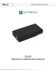
mdm2200_cover_05232005.pdf
5/23/2005
12:04:17 PM
MDM2200
MDM2200 Motor Drive Module
S E R I E S
C
M
Y
CM
MY
CY
CMY
K
Reference & Maintenance Manual
(MDC200, MDC400, MDC800)
Linear Positioning
Rotary Positioning
Motion Controls
Engineered Solutions
Reference & Maintenance Manual
32114 Mallard Ave.
PO Box 409
Tangent, OR 97389-0409
U.S.A.
Phone:
Fax:
Toll Free:
Web:
E-mail:
[541] 791-9678
[541] 791-9410
[888] 754-3111
www.primatics.com
[email protected]
Manual Revision Information
Publication Date
September 2004
September 2004
April 2005
Notes
Added Conventions, Maintenance, and
Troubleshooting. Revised Overview
Updated Look & Formatting
Notice: Any descriptions, drawings, and specifications contained herein are subject to change.
Primatics is not responsible for errors or omissions herein or for incidental damages in connection
with the furnishing or use of this information. This document shall not be reproduced,
photocopied, or duplicated, in whole or in part, without prior written approval of Primatics
Corporation.
For additional specifications, dimensioned drawings and additional information, refer to the
MDM2200 Datasheet available from our website at www.primatics.com.
©Copyright 2005 by Primatics, Inc; All Rights Reserved. Primatics, the Primatics logo, PrimaFlex,
PrimaSeal & SimpleMatch are trademarks of Primatics, Inc.
1
Reference & Maintenance Manual
Manual Revision Information .......................................................... 1
1) Overview ....................................................................................... 3
1.1) Conventions ........................................................................................................................................ 3
2) Introduction – About the MDM2200 Family................................ 4
3) Model Configuration .................................................................... 5
4) Personal Safety
................................................................ 6
5) Installing the MDM2200 Series Motion Control . Error! Bookmark
not defined.
5.1) Configuring the Motion Control Card................................................................................................. 9
5.2) Configuring the MDM2200 ................................................................................................................ 9
5.2.1) Removing the Cover..................................................................................................................... 9
5.2.2) Micro-Step Resolution ................................................................................................................. 9
5.2.3) Peak Current............................................................................................................................... 10
5.2.4) Idle Current ................................................................................................................................ 12
5.2.5) Limit/Home Sensor Voltage....................................................................................................... 12
5.2.6) Replacing the Cover ................................................................................................................... 12
5.3) Locating the MDM2200...................................................................................................................... 7
5.4) Connecting the NI card to the MDM2200......................................................................................... 13
5.4.1) Power Switch and Plug .............................................................................................................. 13
5.4.2) Enable Loop ............................................................................................................................... 13
5.4.3) Motion I/O connector ................................................................................................................. 13
5.4.4) Axis Connector........................................................................................................................... 14
5.4.5) Motion Signal............................................................................................................................. 15
5.4.6) Limit and Home Signals............................................................................................................. 16
6) Operation .................................................................................... 17
6.1) Overview........................................................................................................................................... 17
6.1.1) POWER ON Indicator................................................................................................................ 17
6.1.2) FAULT....................................................................................................................................... 17
6.1.3) DRIVE OK indicators ................................................................................................................ 17
7) Software ...................................................................................... 18
7.1) Start MAX program. ......................................................................................................................... 18
7.2) Load Settings from Configuration Disk ............................................................................................ 18
7.3) Verify Settings .................................................................................................................................. 20
7.3.1) Axis Configuration Settings ....................................................................................................... 21
7.3.2) Axis Settings .............................................................................................................................. 21
7.4) Cycle Axes ........................................................................................................................................ 22
7.5) Saving the Settings............................................................................................................................ 24
8) Troubleshooting & Service........................................................ 25
8.1) Troubleshooting ............................................................................................................................ 25
8.2) Troubleshooting Help.................................................................................................................... 26
8.3) Service........................................................................................................................................... 26
2
Reference & Maintenance Manual
1) Overview
This user guide is designed to help you install and maintain your MDM Series motion
control. Follow these steps to ensure correct installation and maximum life:
Step 1
Review this entire user manual. Become familiar with all installation procedures
prior to integrating your system.
Step 2
Review the safety summary to develop an understanding of standard safety
practices when installing and operating automated equipment.
Step 3
Review installation procedures. For best results, follow these procedures
carefully.
1.1) Conventions
Although this manual specifies NI-7344 compatibility, the MDM will communicate with
motion cards that are members of the NI-73xx family. Some restrictions apply, for
example the MDM2200 can be used with stepper motors.
1.2) NI 7344 Motion Control Cards
The MDM with NI 7344 communications interface is compatible with the following NI
motion controllers:
Table 9-1) Compatible NI Controllers
PCI-7332
PCI-7334
PXI-7334
PCI-7342
FW-7344
PCI-7344
PXI-7344
PCI-7352
PXI-7352
PCI-7354
PXI-7354
PCI-7356
PXI-7356
PCI-7358
PXI-7358
NI Ethernet
Motion
Control
Stepper motors
Stepper motors
Stepper motors
Stepper motors
Stepper motors
Stepper motors
Stepper motors
Stepper motors
Stepper motors
Stepper motors
Stepper motors
Stepper motors
Stepper motors
Stepper motors
Stepper motors
Stepper motors
3
Reference & Maintenance Manual
2) Introduction – About the MDM2200 Family
This manual is intended for use by application engineers and technicians involved in
using Primatics positioning equipment.
The MDM2200 Motor Drive Module acts as an
intermediary between a National Instruments
motion controller and positioning stage(s).The
MDM2200 is a one, two, three or four axis
stepper motor driver with an integrated
interface for a National Instruments motion
controller. The small package includes motor
drives, power supply, NI interface, and
standard Primatics step axis connectors. It
can be directly connected to many Primatics
positioning stages. Third party positioning
stages or axes can also be operated from a
properly configured MDM. A variety of cable
assemblies are available to connect a
positioning stage or axis to the MDM. The
diagram to the left shows the role of a MDM in
a motion control system.
Custom versions of the MDM are also
available to meet specific applications.
Addendums to this manual will be included for
custom configurations.
4
Reference & Maintenance Manual
3) Model Configuration
5
Reference & Maintenance Manual
4) Personal Safety
Please review before installing your motion system
Observe common industrial safety practices when installing and operating automated
equipment.
o
Have power connections made by qualified personnel.
o
Keep fingers and other items out of any opening in the stage while it is in
operation since injury or damage may result.
o
Provide a safe access route and adequate room for servicing.
o
Perform the recommended periodic maintenance described in this document.
o
Verify that the work envelope is free of obstructions before the positioning stage
is powered.
o
Only trained operators of the positioning stage should be allowed near the work
environment.
o
Identify emergency stop circuits and actuators in the workcell. This cuts power to
all axes amplifiers.
o
Note the places in the workcell where pinch points occur, and provide adequate
safety clearance or safety curtain.
o
Never operate the motor in a location that could be splashed by water, exposed
to corrosive or flammable gases or is near combustible substances since this
may cause an electric shock, fire or malfunction.
o
Never touch the motor, driver, or peripheral devices when the power is on or
immediately after the power is turned off. The high temperature of these parts
may cause burns.
6
Reference & Maintenance Manual
5) Installation
5.1) Locating the MDM2200
A typical motion system consists of the MDM, motion control card, axis cables and
positioning stages. The motion controller card is typically housed inside a PC. This card
connects to the interface port in the MDM. Along with the interface port, the MDM has
axis connectors for each axis of travel. These axis connectors connect to stages with axis
cables.
Figure 5-1: MDM2200 Motion System
The MDM must be placed in a convenient location for connection to both the motion
control and your stages.
7
Reference & Maintenance Manual
Figure 5-2: Dimensions of MDM2200
5.2) Rear Panel Information
All connections to the MDM are made as shown in Figures 5-3. Note that the Axis
Connectors are identified as Axes 1 through 4.
Figure 5-3: MDM2200 Connections
8
Reference & Maintenance Manual
5.3) Configuring the Motion Control Card
There are no jumpers or switches to configure for the NI series controllers. Refer to the
documentation that accompanies your NI motion control card for complete information.
5.4) Configuring the MDM2200
The MDM2200 is configured at the factory for the number of axes, motor supply voltage,
and step driver type. Each step driver is also configured with default values for microstep resolution, peak current, and idle current. The voltage supplied for operating
attached limit and home sensors is also configurable. The following sections describe
changing each of these parameters from their factory defaults.
IMPORTANT
All of these configuration settings are to be performed by qualified personnel. Disconnect
the power cord prior to removing the cover and observe ESD precautions when handling
any electronic components.
5.4.1) Removing the Cover
The top cover is secured to the base with 5 screws along both sides of the unit. Remove
all 10 screws and pull the cover off exposing the interior components.
5.4.2) Micro-Step Resolution
The step drives are configured with a 4 bit DIP switch to set the micro-step resolution.
The drives must be removed from the main circuit board to expose the DIP switch. Each
drive is held in place with 4 screws which must be removed before unplugging the drive
from the circuit board (see Figure 5-4 & Figure 5-5).
Figure 5-4 Unplugging Drive from the Circuit Board
9
Reference & Maintenance Manual
Figure 5-5: Micro-step driver
removed from chassis exposing the
micro-step configuration DIP switch.
The DIP switch is set according to Table 5-1 for the desired resolution. The factory
default of is shown in bold.
Table 5-1: Micro-step resolution
Micro-steps Steps/Rev for
per step
1.8 deg motor
2
400
4
800
5
1000
8
1600
10
2000
16
3200
25
5000
32
6400
50
10000
64
12800
125
25000
128
25600
250
50000
FACTORY
DEFAULT
256
51200
Invalid
Invalid
Switch Bit 1
Switch Bit 2
Switch Bit 3
Switch Bit 4
ON
OFF
ON
ON
OFF
ON
ON
ON
OFF
OFF
ON
ON
OFF
ON
ON
ON
OFF
ON
ON
OFF
ON
OFF
ON
ON
OFF
ON
ON
ON
ON
ON
ON
OFF
ON
OFF
ON
OFF
OFF
OFF
OFF
ON
ON
OFF
ON
OFF
ON
OFF
ON
OFF
ON
OFF
ON
OFF
OFF
OFF
OFF
OFF
OFF
OFF
OFF
OFF
ON
ON
OFF
OFF
5.4.3) Peak Current
Peak current is set for each axis with a potentiometer located near the step driver. The
resistance of the potentiometer circuit can be measured across test points marked PEAK
located near each device. For best readings, the step driver should be un-plugged from
the main circuit board. The figure below shows the locations of the potentiometers and a
typical test point.
10
Reference & Maintenance Manual
Figure 5-6: Current adjustment
potentiometers and test points Each drive has two potentiometers:
one for peak current adjustment
(PEAK), and one for idle current
adjustment (RED for reduced). Each
potentiometer circuit can be measured
at test points as indicated in the Figure
at left.
Peak current is set according to the formula:
Rp (ohms) = Peak Current (Amps) x 500
Where Rp is the resistance between the PEAK test points for the step drive.
D5 drive option
Minimum current is 0.4A
Maximum current is 4.0A
Factory Default is 2A corresponding to Rp = 1K ohm
D6 drive option
Minimum current is 1.4A
Maximum current is 7.0A
Factory Default is 4A corresponding to R[peak] = 2K ohm
11
Reference & Maintenance Manual
5.4.4) Idle Current
After one second of inactivity (no steps commanded from the NI controller) the step driver
enters an idle current mode. Idle current is set with a potentiometer circuit similar to that
for the peak current. Idle current is set according to the formula:
Ri (Ohms) = 150 X (Ip x Ii) / (Ip – Ii)
where, Ri is the resistance between the RED (REDuced) test points for the step
drive, Ip is the peak current as set above, and Ii is the idle current.
D5 drive option
Factory Default is 1.54A corresponding to Ri = 1K ohm
D6 drive option
Factory Default is 3.1A corresponding to Ri = 2K ohm
5.4.5) Limit/Home Sensor Voltage
The voltage supplied on pin L of the axis connector is configured by JP1 shown in the
Figure below.
Figure 5-7: JP1: Sensor Voltage
Select –
3 pin jumper marked 12V and 5V.
Shorting jumper is placed between
center pin and end pins to select
voltage.
FACTORY DEFAULT: 12V
5.4.6) Replacing the Cover
The MDM2200 is to be operated under power only when the cover is secured in place.
Replace the cover with the 10 retaining screws after any configuration changes.
12
Reference & Maintenance Manual
5.5) Connecting the NI card to the MDM2200
IMPORTANT
ALL CONNECTIONS ARE TO BE MADE WITH NO POWER APPLIED TO THE MDM2200 OR
THE NI MOTION CONTROLLER.
Refer to Figure 5-3. Use National Instrument SHC68-C68-S Cable (NI P/N 186380-02) to
connect the MOTION I/O connector of the NI motion control card to the MOTION I/O
connector of the MDM2200.
5.5.1) Power Switch and Plug
A standard 110VAC power cord is supplied with the MDM2200. Power input to the unit is
110VAC, Single Phase, 50/60Hz. The power inlet also includes the power switch.
Optionally, the MDM2100 may be configured for 220VAC operation at the factory. This
will be noted on the operating voltage label to the right of the power switch.
5.5.2) Enable Loop
The Enable Loop jumper is part of the Amplifier Enable circuit. This loop must be closed
to enable the motor driver amplifier. If no external circuits are part of the Enable Loop,
the wire jumper installed at the factory must be maintained for normal operation.
5.5.3) Motion I/O connector
All connections to the NI motion controller are made through the Motion I/O connector. A
National Instruments SHC68-C68-S Cable (NI P/N 186380-02) is used for this
connection. There is no connection from the Digital I/O connector on the NI motion
control card to the MDM2200.
13
Reference & Maintenance Manual
5.5.4) Axis Connector
Primatics linear and rotary stages are connected to the MDM chassis using the Step Axis
Cable accessory. The standard cable is 12 ft. long, but cables up to 50 ft. in length can
be used. Only those axes configured at the factory will include a connector. Unused
axes will include a blank plate in place of the connector. If the MDM2100 is used with a
Primatics stage, a Primatics cable assembly is typically used. If a user supplied axis
mechanism is used use Table 5-1 for making connections.
Table 5-2: Step Axis Connector (Motor, encoder, limits, home, temp)
Pin
A
B
C
D
E
F
G
H
J
K
L
M
N
P
R
S
T
U
V
W
X
Y
Name
MOT A+
MOT B+
MOT B<key>
ENC 5V
ENC A+
ENC AENC B+
ENC BENC SHIELD
LIMIT V+
DCCOM
HOME
BRAKE+
BRAKECHASSIS
MOT AMOT B COM
ENC COM
ENC I+
ENC IFLS
Z
RLS
a
b
c
d
e
MOT SHLD
MOT A COM
DCCOM
TEMP
n/c
Function
Motor phase A+
Motor phase B+
Motor phase B Encoder 5V
Encoder A+
Encoder AEncoder B+
Encoder BEncoder shield
Power for limit and home sensors – set by JP1 – DEFAULT: 12VDC
Power return for limit and home sensor
Home input. Connect to DCCOM to activate
Not used – the MDM does not support a brake
Not used
Chassis ground
Motor phase A Motor Phase B common (no internal connection)
no connection
Encoder Index+
Encoder Index Forward limit switch input. Must be connected to DCCOM for normal
operation
Reverse limit switch input. Must be connected to DCCOM for normal
operation
shield for motor cable
Motor Phase A common (no internal connection)
Power return for limit and home sensor
Not used
No connection
14
Reference & Maintenance Manual
5.5.5) Motion Signal
The Motion Signal connector provides access to the breakpoint, trigger, analog inputs,
etc. of the NI motion controller.
Table 5-3: Motion Signals - DB25S (Mates with DB25P)
Pin
1
2
3
4
5
6
7
8
9
10
11
12
13
14
15
16
17
18
19
20
21
22
23
24
25
Name
Trigger 1
Trigger 3
GND
BRKPT 1
BRKPT 3
GND
AIN 1
AIN 3
AREF
SHUTDOWN
+12V
5V
GND
Trigger 2
Trigger 4
GND
BRKPT 2
BRKPT 4
GND
AIN 2
AIN 4
AINGND
GND
-12V
5V
Function
Trigger input 1
Trigger input 3
Digital signal and power supply common
Breakpoint output 1
Breakpoint output 3
Digital signal and power supply common
Analog input 1
Analog input 3
Reference for analog inputs
See NI motion control card documentation
Power supply, +12VDC @ 100 mA
Power supply, +5VDC @ 250 mA
Digital signal and power supply common
Trigger input 2
Trigger input 4
Digital signal and power supply common
Breakpoint output 2
Breakpoint output 4
Digital signal and power supply common
Analog input 2
Analog input 4
Analog input common
Digital signal and power supply common
Power supply, -12VDC @ 100 mA
Power supply, +5VDC @ 250 mA
15
Reference & Maintenance Manual
5.5.6) Limit and Home Signals
The NI motion controller monitors limit and home sensors through the MDM2200. The
MDM2100 can be configured to supply either 5V or 12V DC power for the limit and home
sensors. The default setting is 12V. For ease of setting the limit switch voltage, jumper
JP1 has been provided. JP1 is located inside the MDM2200 on the main printed circuit
board near the power switch. The cover must be removed to access JP1.
IMPORTANT! Only qualified personnel should adjust JP1. Disconnect the power cord
before removing the top cover. Replace the top cover when the adjustment is complete.
Electrically, each sensor should sink a minimum of 2mA from the sensor input (pins N, Y,
or Z) to DCCOM (pin M). The sense or polarity of the signals is programmable in the NI
motion controller. Figure 5-8 shows an equivalent schematic for the limit, home, and
temperature inputs.
Figure 5-8: Sensor Input Circuit Diagram
16
Reference & Maintenance Manual
6) Operation
6.1) Overview
The MDM2200 is be configured as a one, two, three or four axis stepper motor drive with
integrated interface to the National Instruments motion controller. Two drive options are
available. The unit operates directly from line voltage to operate the motor at the
specified bus voltage. The interface to the NI motion controller is via the MOTION I/O
connector on the controller. Connections to the axes are through the Primatics standard
stepper axis connector described in section 5.4.4.
For all the drive options, there are no hardware or software drive configurations
necessary.
6.1.1) POWER ON Indicator
The POWER ON indicator light is on whenever AC power is provided to the MDM2200
and the power switch is in the on state.
6.1.2) FAULT
The operation of the FAULT indicator is representative of a system fault. When not
illuminated, it indicates that the system is in a state capable of running. Any of the
following errors will cause the FAULT indicator to be on:
o
o
A broken connection to the NI controller
Open Enable Loop
6.1.3) DRIVE OK indicators
The DRIVE OK indicators individually illuminate whenever the respective drive is enabled
with no faults. Any of the conditions listed below will prevent a given drive from being
enabled:
All drive options
o Enable Loop jumper is open
o Motion I/O cable disconnected from NI-7344
o Power to the NI-7344 is off
o Axis is DISABLED from NI 7344
o Phase-to-phase in the motor
o Phase-to-ground short in the motor
17
Reference & Maintenance Manual
7) Software
This section describes how to use MAX (National Instrument’s Measurement &
Automation Explorer) to confirm that the MDM2200 is operational. Make the hardware
connections described in Section 5-4.
7.1) Start MAX program.
Figure 7-1: MAX Opening Dialog
7.2) Load Settings from Configuration Disk
Open the Devices and Interfaces selection of the Configuration Menu and highlight the
PCI-73xx device.
Figure 7-2: Select the PCI-73xx Device
Load the settings file from the configuration disk sent with the controller. This is done by
selecting the Import Settings selection from the File Menu.
18
Reference & Maintenance Manual
Figure 7-3: Select Import Settings
The settings file has the same name as the serial number of the MDM.
Figure 7-4: Selecting the Import Settings File
Next, the settings need to be selected as the current settings. This is done by choosing
the Change Current Settings menu selection from the File Menu (See Figure 7-3 Select
Import Settings). From the Change Current Settings Dialog select the settings just
imported and press the Change button.
19
Reference & Maintenance Manual
Figure 7-5: Select Initialization Settings
Apply the settings to the Motion Controller by choosing Initialize from the File Menu (See
Figure 7-3 Select Import Settings).
7.3) Verify Settings
The File README.TXT Describes which stages were assigned to which Controller Axis
(This applies to the case where stages are purchased with the MDM). For the controller
axes not associated with purchased stages, a stepper motor is connected to the axis for
testing at the factory.
20
Reference & Maintenance Manual
7.3.1) Axis Configuration Settings
Figure 7-6: Axis Configuration Settings
Each Axis of the controller should be assigned the Stepper Axis Type. Each Axis of the
MDM that is connected to a stepper motor should be enabled.
7.3.2) Axis Settings
The Motion I/O Axis Settings will need to be set to match the Stepper Motor connected to
the axis. This has already been done for stages that are purchased with the MDM.
21
Reference & Maintenance Manual
Figure 7-7: Motion I/O Settings
7.4) Cycle Axes
The 1-D Interactive Dialog can be used to cycle the axis between two points.
22
Reference & Maintenance Manual
Figure 7-8: 1-D Interactive Utility
The steps to cycling the axes are to move the axis to approximately the center of travel,
reset the position, specify the trajectory parameters for cycle mode, apply the parameters
and then start cycling.
To command the axis to move, specify the Trajectory Parameters. The README.TXT
file specifies the encoder ratios for each axis in counts/mm or counts/degree, depending
upon the stage. After specifying the Trajectory Parameters, press the Apply button.
Press the Start menu selection at the top of the dialog to initiate the move.
To cycle between two points, check the Cycle Mode check box.
23
Reference & Maintenance Manual
Figure 7-9: 1-D Interactive Cycle Mode
In cycle mode, the axis moves between the Cycle Position and the Target Position. After
reaching each position, the program pauses the amount of time specified in the Cycle
Dwell Time and then initiates the move to the other position. When the parameters are
set press the Apply button and then the Start Menu Item. The Halt menu selection will
terminate the cycling.
Note: The program allows several stages to cycle simultaneously. Just start one axis
cycling and then, under Trajectory Parameters, select the next Axis.
7.5) Saving the Settings
When the session is over, it is advisable to save the settings to disk. This can be done
by selecting the Export Settings menu selection from the File Menu (See Figure 7-3
Select Import Settings).
24
Reference & Maintenance Manual
8) Troubleshooting & Service
8.1) Troubleshooting
Symptom
POWER ON indicator is off
POWER ON indicator
flashes
FAULT indicator is on
AXIS OK indicator is off
Step motor won’t move when
commanded.
Limit switch is always
violated
Discussion
Verify that unit is plugged in to a powered outlet.
Verify that power switch is on.
Verify that input fuse near power switch is not blown.
This indicates a short in the power supply. Disconnect anything
plugged into the axis connectors. If the indicator stops flashing
when a particular connector is removed, verify that the external
wiring to that connector does not short either the 5V (encoder
power) or Limit V+ signals to DCCOM
Verify that the MOTION I/O cable is connected between the
MDM2200 and the NI motion controller and that the controller has
power.
Verify that the ENABLE LOOP circuit is closed between the two
terminals of the jumper.
Verify that the FAULT indicator is off – any FAULT will prevent an
AXIS OK indicator from turning on.
Verify that the axis is enabled by the NI controller.
Verify that there are not short circuits between the step motor
phases or between any phase and ground.
Verify that the AMP OK for the specific axis is ON.
Verify that the motor is properly connected to the Axis connector.
Verify that the limit switches are not violated in the NI software. A
violated limit will prevent motion in the direction of the violated
limit.
Verify that the axis is properly configured for a step motor in the
NI software.
The sense of the limit switches are configured with the NI
software. NOTE: The factory default requires normally closed
circuits between the limit switch inputs and DCCOM.
25
Reference & Maintenance Manual
8.2) Troubleshooting Help
For further assistance contact the factory:
M-F 8AM to 5PM Pacific Time
Phone:
Fax:
Toll Free:
Web:
E-mail:
[541] 791-9678
[541] 791-9410
[888] 754-3111
www.primatics.com
[email protected]
8.3) Service
Should your device require factory service, contact the factory for a Return Materials
Authorization (RMA). When inquiring about an RMA please have the following
information available:
o Your contact information (name, phone, email, address)
o Unit Serial Number (located on label near the power switch)
o Symptom of problem
o History of troubleshooting steps already taken
26