1
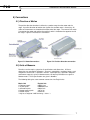
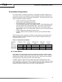
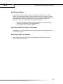
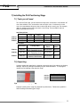
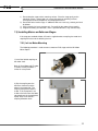
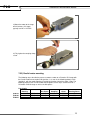
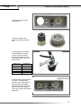
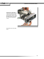
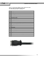
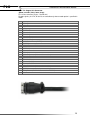
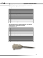
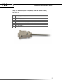
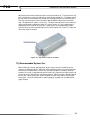
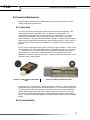
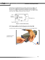
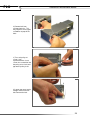
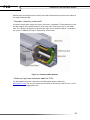
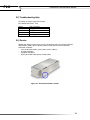
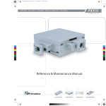
PLG
Reference & Maintenance Manual
PLG
Reference & Maintenance Manual
1
PLG
Reference & Maintenance Manual
32114 Mallard Ave.
PO Box 409
Tangent, OR 97389-0409
U.S.A.
Phone:
Fax:
Toll Free:
Web:
E-mail:
[541] 791-9678
[541] 791-9410
[888] 754-3111
www.primatics.com
[email protected]
PLG110, PLG160 & PLG210 Manual
Revision Information
Revision Date
Oct 2003
March 2003
April 2005
June 2006
November 2006
January 2007
January 2008
September 2014
Jan 2015
Notes
Changed recommended grease from Lithium
#2 to NSK Clean room grease
Updated formatting & content
Added table 7-2
Updated PLG options images
Updated Ordering Info
Deleted P4 option
Deleted model configurations
New Logo
Notice: The descriptions, drawings, and specifications contained herein are subject to change.
Primatics is not responsible for errors or omissions herein or for incidental damages in connection
with the furnishing or use of this information. This document shall not be reproduced,
photocopied, or duplicated, in whole or in part, without prior written approval of Primatics
Corporation.
For Specifications, Dimensioned Drawings and additional information, refer to the PLG Datasheet
available from our website at www.primatics.com.
©Copyright 2008-2015 by Primatics, Inc; All Rights Reserved. Primatics, the Primatics logo,
PrimaFlex, PrimaSeal & SimpleMatch are trademarks of Primatics, Inc.
2
PLG
Reference & Maintenance Manual
PLG110, PLG160 & PLG210 Manual Revision Information ............................. 2
2) Introduction – About the PLG Family ........................................................... 5
3) Models ............................................................................................................. 5
4) Personal Safety ............................................................................................... 6
5) Conventions .................................................................................................... 7
5.1) Direction of Motion ............................................................................................................ 7
5.2) Units of Measure ............................................................................................................... 7
6) Installation Preparations ................................................................................ 8
6.1) Linear Motors .................................................................................................................... 8
6.2) Heat and Humidity............................................................................................................. 9
6.3) Contamination ................................................................................................................... 9
6.4) Electrical Noise ............................................................................................................... 10
6.5) Using the PLG in a Class 10 Cleanroom ........................................................................ 10
6.6) Using the PLG in a Vacuum ............................................................................................ 10
7) Installing the PLG Positioning Stage .......................................................... 11
7.1) Tools you will need.......................................................................................................... 11
7.2) Unpacking ....................................................................................................................... 11
7.3) Installing Motors on Ballscrew Stages ............................................................................ 12
7.3.1) In-Line Motor Mounting ................................................................................................ 12
7.3.2) Parallel motor mounting ............................................................................................... 13
7.4) Mounting surface preparation ......................................................................................... 16
7.5) Mounting the Stage ......................................................................................................... 16
7.6) Electrical Connections..................................................................................................... 17
7.6.1) Color Codes for Pigtailed Cable ................................................................................... 22
7.6.2) Hall Effect Commutation Sequence ............................................................................. 23
7.7) Home and Limit Sensors ................................................................................................. 23
7.7.1) Home Options: ............................................................................................................. 24
7.8) Limit and Home Switch Adjustment ................................................................................ 25
7.9) Recommended System Test ........................................................................................... 26
8) Preventive Maintenance ............................................................................... 27
8.1) Lubrication ....................................................................................................................... 27
8.2) Protection Belts ............................................................................................................... 27
8.2.1) Replacing Belts at the End Opposite of the Cable Exit................................................ 28
8.2.2) Replacing Belts at the End of the Cable Exit ............................................................... 30
9) Troubleshooting & Service .......................................................................... 31
9.1) Troubleshooting FAQ’s ................................................................................................... 31
9.2) Troubleshooting Help ...................................................................................................... 34
9.3) Service ............................................................................................................................ 34
3
PLG
Reference & Maintenance Manual
1) Overview
This user guide is designed to help you install and maintain your PLG Series linear
positioning stage application. Follow these steps to ensure correct stage installation and
maximum stage life:
Step 1
Review this entire user manual. Become familiar with all installation procedures
prior to integrating your system.
Step 2
Review the safety summary to develop an understanding of standard safety
practices when installing and operating automated equipment.
Step 3
Familiarize yourself with the conventions summary.
Step 4
Review installation procedures. For best results, follow these procedures
carefully.
Step 5
Once you successfully complete all the installation procedures, you will be
ready to install and operate your stage.
Step 6
Review preventive maintenance section for proper lubrication schedule.
4
PLG
Reference & Maintenance Manual
2) Introduction – About the PLG Family
Each Primatics PLG positioning stage is designed for precision movement in one axis.
The individual PLG stage can be ordered in a variety of configurations, from the differing
cross-sectional sizes and lengths to the numerous motor options to the various protection
levels. The stages can be stacked to make X-Y or X-Y-Z systems.
There are three model Series in the PLG Family: PLG110, PLG160 & PLG210. Each is
briefly described in the table below.
PLG110
PLG160
PLG210
Basic Width x Height (mm)
110 x 60
160 x 80
210 x 90
Travel Lengths (mm)
50 to 600
50 to 800
100 to 1200
Drive Types
Linear Motor or Ballscrew
Encoder Option
Rotary or Linear
Payload (kg)
25
50
100
Each can be configured with options listed in Section 3.
Many customers choose the Primatics Motion Drive Chassis (MDC) to power PLG
stages. The MDC is a modular system that packages motor drivers, encoder interfaces,
power supplies and safety systems into a single chassis. It acts as an intermediary
between a Galil Optima, National Instruments 7344 or Delta Tau PMAC II motion control
cards and a Primatics positioning stage. Pre-wired high-flex cables are available to allow
a convenient connection from the stage to the MDC chassis. The MDC drive chassis
rd
interfaces 3 party controllers via a removable interconnect module. These interconnect
modules conform to each manufacturers interconnect cable, and internally route all the
command and I/O signals.
Optionally, a Primatics positioning stage can be used with many third party controller and
amplifier systems. In this case, a pigtailed cable is available to simplify the connection
between the PLG stage and controls.
3) Models
Refer to the PLG Datasheets available from www.primatics.com for current model
options. Some options and configurations referenced in this manual have been
discontinued. The information remains here for reference only.
5
PLG
Reference & Maintenance Manual
4) Personal Safety
Please review before installing your positioning stage
Observe common industrial safety practices when installing and operating automated
equipment.
o
Have power connections made by qualified personnel.
o
Keep fingers and other items out of any opening in the stage while it is in
operation since injury or damage may result.
o
Provide a safe access route and adequate room for servicing.
o
Perform the recommended periodic maintenance described in this document.
o
Verify that the work envelope is free of obstructions before the positioning stage
is powered.
o
Insure that you have the feedback wired properly to the controller before applying
power to the positioning stage. Improper feedback connections can cause a
motor run-away condition that has the potential to damage the stage and injure
an operator.
o
Only trained operators of the positioning stage should be allowed near the work
environment.
o
If so equipped, identify emergency stop circuits and actuators in the workcell.
o
Note the places in the workcell where pinch points occur, and provide adequate
safety clearance or safety curtain.
o
Never operate the motor in a location that could be splashed by water, exposed
to corrosive or flammable gases or is near combustible substances since this
may cause an electric shock, fire or malfunction.
o
Never touch the motor, driver, or peripheral devices when the power is on or
immediately after the power is turned off. The high temperature of these parts
may cause burns.
6
PLG
Reference & Maintenance Manual
5) Conventions
5.1) Direction of Motion
The positive direction of motion is defined as a motion away from the motor end of a
stage. A positive direction of motion also signifies the encoder count is increasing. All
cables and connectors are located at the motor end of the stage. The reverse limit switch
is located on the motor end and the forward limit switch is located on the opposite end of
the stage. Figure 5-2 illustrates this convention.
Figure 5-1: Name Conventions
Figure 5-2: Positive direction convention
5.2) Units of Measure
Primatics uses the metric system for all specifications and dimensions. All linear
dimensions are specified in millimeters. Accuracy, repeatability, resolution, flatness and
straightness for the PLG is specified in microns. Load capacity is specified in kilograms
and moment capacity is given in Newton-meters. All torque specifications are given in
Newton-meters. Thrust specifications are given in Newtons.
The following table gives some common conversions into English units:
Metric Unit
English Unit
1 Kilogram equals
0.0685 slug*
1 micron equals
0.0000394 inch
1 millimeter equals
0.0394 inch
1 Newton-meter equals
8.85 in-lbs
1 Newton equals
0.2248 lbs
2
*1 Kg has a weight of 2.205 lb when g = 9.8 m / s
7
PLG
Reference & Maintenance Manual
6) Installation Preparations
This section outlines installation environments. Unfavorable installation conditions may
cause electric shock, fire, or breakdown. Certain breakdown situations or malfunctions in
particular may lead to serious injury or other consequences. Assure that the unit is used
under the following installation conditions:
o
o
o
o
o
o
Indoors, free from being splashed by water
No corrosive or inflammable gases present
Well ventilated place, minimum level of dust or waste
An environmental temperature range between 0-40°C, and humidity between 2080% RH (location with no condensation) Note - These values show the range in
which operation can be carried out safely, but not the environmental range in
which stages accuracy can be guaranteed. Stage accuracy can be guaranteed at
20°C +/- 1°C.
Location should not be affected by electrical noise.
Location should be where inspection and cleaning can be performed without
difficulty.
The PLG features built-in protection to counteract some negative environmental effects.
Please see section 3, the PLG datasheet, or refer to Table 6-1 below to confirm your
selected protection (P) level.
Table 6-1: Protection Level Options
Protection
Level
Level 1 (P1)
Level 2 (P2)
Level 4 (P4)
Level 5 (P5)
Hardcover
Belts
Yes
Yes
Yes
Yes
No
Yes
No
Yes
Clean
Grease
Yes
Yes
Yes
Yes
High Pressure
Purge
No
Yes
No
No
High Flow
Purge
No
No
Yes
Yes
Class 10
Prep
No
No
Yes
Yes
6.1) Linear Motors
Linear motors have large magnetic flux that can draw ferrous metals inside them from
large distances, destroy magnetic media, and disrupt some electronic circuits. Materials
attracted to the magnets can pinch fingers and cause injury. Great care must be taken
when operating less than 25mm from the surface of the motor.
In addition, braking is difficult for linear motors making them inappropriate for many
vertical applications. Make sure no load is attached to the linear motor stage when stage
is first connected to the electronics. Linear motors can generate large accelerations and
improper wiring to the control system can result in a high-speed crash.
8
PLG
Reference & Maintenance Manual
6.2) Heat and Humidity
All positioning stages are assembled and tested at 20°C. Any stage calibrations are also
performed at 20°C. For optimum accuracy the ambient temperature should be
maintained at 20°C. Deviations from this nominal temperature may result in degraded
accuracy performance.
Large thermal gradients in the interior of the stage can result from motor heat created by
high acceleration moves. Care must be taken to limit the duty cycle of the linear motor to
maintain stage performance. Airflow across the motor will help minimize thermal
expansion effects and increase the allowable duty cycle.
Ballscrew driven stages are also susceptible to thermal expansion effects. The ballscrew
nut can create a localized thermal gradient if driven at high speeds. Both high pressure
air purge and high flow air purge through the stage can help minimize ballnut heating, the
latter being most effective.
6.3) Contamination
Applications in dirty or dusty environments require the electrical, optical and mechanical
components to be protected. The standard belt protection and high-pressure (6090psi)/high flow air purge system (P2) is sufficient for environments generating moderate
quantities of 0.5 mm and larger particles. It is important to be aware of the amount of
airflow going into the stage; air flowing into a stage can push the belts against the slots
that they run in and cause an increase in the amount of drag created by the belts. This
can affect the performance of the stage. Adverse effects may include increased settling
times or decreased repeatability of the stage.
For dusty environments or applications with continuous exposure to smaller
contaminants, an optional low pressure/ high flow purge system is necessary (P5). It
allows movement of 5-15 cfm of low-pressure air through each stage. Additional
protection must be used for stages that will be splashed with fluids.
Airflow through a stage must be filtered and dry. The filtration system should reject
particles larger than 2 microns. Air pressures between 60-100 psi are sufficient for
convection cooling. A typical air source can be made suitable with the addition of an
inline desiccant dryer and filter/regulator assembly. Humidity should be less than 85%
and there should be no condensation in the environment in which the stage is used.
9
PLG
Reference & Maintenance Manual
6.4) Electrical Noise
Electrical noise is the corruption of signals carried over low voltage wires. Encoder
signals can be corrupted resulting in spurious encoder counts thus causing the stage to
drift. Grounding, shielding, and spatial separation are all countermeasures to reduce the
influences of electrical noise on performance. You can minimize the potential for
electrical noise by observing the following installation precautions:
o
o
o
Physically separate low voltage conductors from those carrying high voltage.
Ensure that all components are properly grounded.
Ensure that all wiring is properly shielded.
6.5) Using the PLG in a Class 10 Cleanroom
For operation in a Class 10 Cleanroom, the PLG stages must be configured with the P4
or P5 Protection options.
6.6) Using the PLG in a Vacuum
Many configurations of the PLG Family are compatible with operation in a vacuum.
Contact us for more information.
10
PLG
Reference & Maintenance Manual
7) Installing the PLG Positioning Stage
7.1) Tools you will need
To install the PLG stage, you will need the hex wrenches and fasteners listed below. “M”
sizes refer to Metric sizes, and fractions refer to English sizes. In reference to screw
sizes, the second dimension given refers to the length of the screw in mm. For example,
“M4 x 16” would require an M4 screw that is 16 mm long. The term BHSC refers to
Button Head Stainless Screws.
Hex Wrench Sizes
Base Plate
Carriage
Plate
PLG110
M3
M2.5
PLG160
M4
M2.5
PLG210
M5
M3
Top & Side
Plates
M2
M2
M2.5
Coupling
Motor Mount
7/64
7/64
5/32
M4
M4
M4
Screw Sizes
Base Plate
PLG110
M4 x 16
PLG160
M5 x 20
PLG210
M6 x 16
Carriage Plate
(8) M3 x 8, (8) M3 x 12
Zinc Plated Alloy Screws
(16) M2 x 12
Zinc Plated Alloy Screws
M4 x 16
Stainless Steel Screws
Top & Side
Plates
Motor
Mount
M3 x 6 BHSC
M5 x 12
M3 x 6 BHSC
M5 x 12
M4 x 6 BHSC
M5 x 12
7.2) Unpacking
Carefully remove the stage from its shipping crate and inspect it for evidence of shipping
damage. Report any damage immediately to your authorized dealer. If so equipped,
remove the red shipping clamp from the stage.
PLG110
PLG160
PLG210
Hex Wrench Required
M3
M3
M4
Figure 7-1: PLG210 Shipping Clamp
Improper handling of the stage may degrade its performance. Follow these guidelines
when handling and mounting your stage.
11
PLG
Reference & Maintenance Manual
1) Do not drop the stage onto its mounting surface. Place the stage gently on the
mounting surface. Impact loads can cause high spots on mounting surfaces,
misalignment of drive components and warping of the base.
2) Do not drill holes into the stage. If additional holes are necessary, contact your local
distributor.
3) Lift the stage by its base structure only. Do not lift by the motor drive assembly.
4) Stage disassembly and alteration, unless specified otherwise, may void warranty.
7.3) Installing Motors on Ballscrew Stages
If the stage was ordered without a Primatics supplied motor or coupling, the motor and
coupling will have to be installed by the user.
7.3.1) In-Line Motor Mounting
The following procedure is used to mount a motor on PLG stages with the M1 Motor
Mount Option.
1) Install the flexible coupling on
the motor shaft.
Note: A Servo Motor with Encoder
is shown, but the procedure is
similar for a step motor.
2) Slip the coupling over the
ballscrew shaft and seat the
motor in the motor pilot. The
coupling clamp bolt should be
visible. If the clamp bolt is not
visible or the ballscrew shaft does
not extend past the clamping bolt,
repeat Step 1 and slide the
coupling forward or back.
12
PLG
Reference & Maintenance Manual
3) Mount the motor to the stage
with 4 fasteners. All stages
typically use M5 x 12 SHCS.
4) Fully tighten the coupling clamp
screw.
7.3.2) Parallel motor mounting
The following steps describe the process to mount a motor on a Primatics PLG stage with
the Parallel motor mount, options M2 (position 1, as seen in the following photos) or M3
(position 2, with the motor mounting in parallel on the other side of the stage). Note: The
following photos are for a PLG110 with the M2 option, but the steps are the same for a
PLG160 or PLG210 stage as well as the M3 options.
List of tools
Parallel
Housing
PLG110
M3
PLG160
M3
PLG210
M4
Standoff
1/4” Wrench
1/4” Wrench
1/4” Wrench
Ground
Wire Screw
M2.5
M2.5
M2.5
Shaft
Coupling
Varies
Varies
Varies
Cable
Cover
M2.5
M2.5
M2.5
Parallel
Housing Cover
M2
M2
M2.5
13
PLG
Reference & Maintenance Manual
1) Remove the cover of the
parallel mount.
2) Locate the motor shaft
coupling, belt pulley and drive
belt.
3) Install the pulley and motor
shaft coupling on the motor
shaft. Use a wrench for the
coupling and band wrench (or
some other soft tool) to secure
the belt pulley.
Motor Shaft
1/4”
3/8”
8mm
9mm
1/2”
14mm
Socket Size
1/2”
5/8”
16mm
16mm
3/4”
22mm
4) Mount motor to parallel mount
as shown. The motor pulley
should be in the same plane as
the drive pulley and spaced
about 5mm from the surface of
the housing. Repeat Step 3 as
necessary. Loop the Belt around
both pulleys.
14
PLG
Reference & Maintenance Manual
5) Belt tension is adjusted by
loosening the fasteners indicated
in Step 4 and sliding the motor
mount toward the motor. Tighten
the adjustment screws to secure
the mount in place. Use an M3
Hex Driver for the adjustment
screws.
6) Install the cover to the motor
mount.
15
PLG
Reference & Maintenance Manual
7.4) Mounting surface preparation
The characteristics of the surface the positioning stage is mounted to will have a large
effect on system performance. An accurate and flat positioning stage will conform to the
shape of its mounting surface, therefore a flat mounting surface is required. In the
absence of a sufficiently flat surface, a three point mounting scheme can be utilized to
rely on the inherent flatness of the stage. This technique can introduce negative dynamic
effects in moment load applications because a large portion of the stage base is not in
contact with the mounting surface. The flatness and straightness specifications can be
affected under large loads. For best results in maintaining stage specifications we
suggest the following:
1) Use a laboratory Grade AA granite surface plate
2) Before mounting stage, inspect for burrs or dings on the stage mounting surfaces
3) Clean all mounting surfaces with acetone
In the absence of a granite surface plate, we recommend a base plate made of the same
material as the base of the stage. A mounting surface constructed out of a material
different from the stage base material can introduce warping in the stage in the presence
of a thermal gradient. The surface flatness should match the requirements of the
application; a good starting point is to have the mounting surface flat to less than 5-8µm.
Figure 7-2: Mounting Hole locations
7.5) Mounting the Stage
1) Remove Side Covers.
2) Insert Mounting Screws.
3) Tighten Screws. Access holes are provided for hex tool. When mounting the
base down to the surface plate, tighten the bolts at one end of the stage first and
move towards the other end.
4) Replace Side Covers.
16
PLG
Reference & Maintenance Manual
7.6) Electrical Connections
Electrical connections to the stages depend on the type of stage in use. All PLG models
with linear motors or frameless motors are terminated with a 450mm flexible cable with a
28 position circular connector on the end. The pin-out of this connector is shown with
Table 7-1. This particular configuration is optimized for use with Primatics MDC drive
chassis via an extension cable. Connections to other drives and controls are also made
through this connector.
PLG models with M1, M2, or M3 Motor Mount options provide all electrical connections
through DSub connectors. Models without internal encoders use a 9 position DSub
described in Table 7-4. Models with internal encoders use a high-density 15 position
DSub described in either Table 7-3 (internal brake option (B2)) or 7-4 (no internal brake
option (B1)).
A popular option for applications not using the Primatics MDC drive chassis is the
pigtailed extension cable. This is similar to the extension cable used to connect a stage to
the MDC drive chassis, except the end that connects to the motor drive and controller is
un-terminated. Section 7.6.1 shows the conductor assignments for this cable (when
ordered with a ballscrew drivetrain and without an encoder).
17
PLG
Reference & Maintenance Manual
Table 7-1: Axis Connector (Motor, encoder, limits, home, temp)
for Linear motors and frameless motor options
FCI circular connector, 28 pins, size 20 shell
Pin
A
B
C
D
E
F
G
H
J
K
L
M
N
P
R
S
T
U
V
W
X
Y
Z
a
b
c
d
e
Function
Motor A
Motor B
Motor C
Motor Shield
Encoder 5V – power for encoder
Encoder A+ output
Encoder A- output
Encoder B+ output
Encoder B- output
Encoder Shield
12 - 24VDC - for limit & home
DCCOM
Home
Brake release output (24VDC) for optional brake
Brake return for optional brake
Stage Base
Hall V+
Hall VEncoder 0V
Encoder Index +
Encoder Index Forward Limit Switch
Reverse Limit Switch
Signal Shield
Hall A
Hall B
Temperature monitor – connect to DC Common for temperature OK
Hall C
18
PLG
Reference & Maintenance Manual
Table 7-2: Stepper Axis Connector
(Motor, encoder, limits, home, temp)
FCI circular connector, 28 pins, size 20 shell
Encoder signals, pins E-K, W and X, are available only when encoder option is specified in
model.
Pin
A
B
C
D
E
F
G
H
J
K
L
M
N
P
R
S
T
U
V
W
X
Y
Z
a
b
c
d
e
Function
Motor A+
Motor B+
Motor B<Key>
Encoder 5V
Encoder A+
Encoder AEncoder B+
Encoder BEncoder Shield
Limit Sensor Power (12VDC)
DCCOM
Home (Reserved, N.C.)
Not Used
Not Used
Chassis Ground
Motor AMotor B Common (No internal connection)
Encoder Ground
Encoder Index +
Encoder Index Forward Limit Sensor
Reverse Limit Sensor
Motor Shield
Motor A Common (No internal connection)
DCCOM
Temp Sensor (Not Used, Connected to DCCOM)
Not Used
19
PLG
Reference & Maintenance Manual
Table 7-3: Signal Connector: Internal encoder, limits, home, and brake
for Ballscrew motor with encoders and brake
Hi-Density Male Dsub 15P
Pin
1
2
3
4
5
6
7
8
9
10
11
12
13
14
15
Function
12 - 24VDC – for limit & home
DCCOM
Forward Limit Switch
Reverse Limit Switch
Home
Brake release output (24VDC)
Brake return
Encoder 5V (power for encoder)
Encoder 0V
Encoder A+ output
Encoder A – output
Encoder B+ output
Encoder B – output
Encoder Index + output
Encoder Index – output
Table 7-4: Signal Connector: Internal encoder, limits, home, no brake
for Ballscrew motor with encoders and no brake
Hi-Density Male Dsub 15P
Pin
1
2
3
4
5
6
7
8
9
10
11
12
13
14
15
Function
12 - 24VDC – for limit & home
DCCOM
Forward Limit Switch
Reverse Limit Switch
Home
No connection
Encoder shield
Encoder 5V (power for encoder)
Encoder 0V
Encoder A+ output
Encoder A – output
Encoder B+ output
Encoder B – output
Encoder Index + output
Encoder Index – output
20
PLG
Reference & Maintenance Manual
Table 7-5: Signal Connector: Limits, home, brake (no internal encoder)
for Ballscrew motor with no encoder
Male DSub 9P
Pin
1
2
3
4
5
6
7
8
9
Function
12 – 24 VDC – for limit & home
DCCOM
Forward Limit Switch
Reverse Limit Switch
Home
Brake release output (24VDC) for optional brake
Brake return for optional brake
No connection
No connection
21
PLG
Reference & Maintenance Manual
7.6.1) Color Codes for Pigtailed Cable
Cable consists of 3 independent shielded “pods”: One for motor signals, one for encoder
rd
signals & a 3 for sensors and brake. Each of the pods is described below.
Cable 1
█
█
□
█
Color
Black
Red
White
Shld
Function
Motor R
Motor S
Motor T
Motor Shield
Cable 2
█
□
█
█
█
█
█
█
█
Color
Red
White
Yellow
Green
Blue
Shld
Black
Orange
Brown
Function
Encoder 5V
Encoder A+ output
Encoder A- output
Encoder B+ output
Encoder B- output
Encoder Shield
Encoder Common
Encoder Index +
Encoder Index -
Cable 3
█
█
□
□/█
□/█
█
█
█
█
█
█
█
█
█
Color
Green
Blue
White
Wht/Red
Wht/Black
Shld
Black
Brown
Violet
Gray
Red
Orange
Tan
Yellow
Function
12VDC
DCCOM
Home
Brake release output (24VDC)
Brake return
Chassis
Hall V+
Hall VForward Limit Switch
Reverse Limit Switch
Hall A
Hall B
Temperature Monitor
Hall C
22
PLG
Reference & Maintenance Manual
7.6.2) Hall Effect Commutation Sequence
In the event that user amplifier and controls are being implemented, use the following
motor commutation timing charts.
Figure 7-3: Motor commutation chart
Figure 7-4: Timing diagram for the encoder signals
7.7) Home and Limit Sensors
Each PLG stage includes Forward and Reverse Limit sensors and a Home sensor.
Models ordered with internal motors also include a Motor Temperature Switch. Figure 7-4
shows the equivalent schematic for these switches.
23
PLG
Reference & Maintenance Manual
Figure 7-4: Equivalent Limit, Home, and Temp circuit schematic
7.7.1) Home Options:
The Home switch is ordered in either the Normally Closed (H1) or Normally Open
(H2) configuration
H1: Switch is closed when carriage is between the negative (reverse)
end of travel and the home transition point. It is open from the transition
point to forward end of travel.
H2: Switch is open when carriage is between the negative (reverse) end
of travel and the home transition point. It is closed from the transition
point to forward end of travel.
7.7.2) Limit Options:
The Limit switches are ordered in either the Normally Closed (L1) or Normally
Open (L2) configuration
L1: When the carriage is in the normal operating range of travel, both
limit switches are closed. When the carriage encounters a limit the switch
opens. The switch will close again when the carriage is moved away
from the switch.
L2: When the carriage is in the normal operating range of travel, both
limit switches are open. When the carriage encounters a limit the switch
closes. The switch will open again when the carriage is moved away
from the switch.
24
PLG
Reference & Maintenance Manual
7.8) Limit and Home Switch Adjustment
The limit and home switch positions are preset at the factory. The limits are nominally set
to yield slightly more travel than specified in the model configuration. The nominal home
switch transition point is about 2mm to the positive side of the center of travel. Figure 7-5
shows the default signal transition points for a 200mm travel stage.
Figure 7-5: Limit and Home Sensor Transition Ranges
The home and limit signals are each produced by separate reflective sensors mounted to
the underside of the carriage. A white reflective strip (the home vane) mounted on the
inside of the stage runs the length of the stage and is viewed by each sensor. A special
non-reflective black tape is applied to the home vane. Each switch is closed when
viewing the white area and is open when viewing the non-reflective tape. Figure 7-6A
shows the tape configuration for the normally closed sensor options (H1, L1). Figure 7-6B
shows the tape configuration for the normally open sensor options (H2, L2). The point at
which each signal transition occurs can be adjusted by adding or removing the nonreflective tape. The home sensor can also be reconfigured to a momentary switch by
adding or removing tape.
Figure 7-6A: Home Vane
Configuration H1, L1 Options
(Normally Closed)
Figure 7-6B: Home Vane
Configuration H2, L2 Options
(Normally Open)
25
PLG
Reference & Maintenance Manual
Adjustment of the limit and home positions can be achieved easily. The white metal strip
on the interior of the stage has three pieces of black tape affixed to it. The bottom half of
the strip contains two narrow pieces of tape that correspond to the limit switch positions.
The limits transition points can be moved by adding additional black tape to the white
strip. No adjustment of cables is necessary. The home transition point can be moved as
well or converted to a momentary switch in a similar fashion. A 3 inch length of tape is
supplied with each stage for this purpose. Longer pieces are available upon request.
The Top Cover must be removed to gain access to the Home Vain. Figure 7-7 shows the
Top Cover fastener locations.
Figure 7-7: Top Cover fastener locations
7.9) Recommended System Test
Before attaching a load or applying power to your stage, verify the encoder and limit
switches are working properly. Move the stage carriage by hand in the positive direction
and verify the encoder count is increasing. Runaway conditions caused by miswired
encoders can result in stage damage and personal injury. Move the carriage to each end
of travel to ensure limit switches are working properly. When closing the position loop for
the first time, set the torque limit of your controller to a low value and use conservative
tuning gains. Once the control loop is working properly, payloads can be added to the
stage carriage.
26
PLG
Reference & Maintenance Manual
8) Preventive Maintenance
Performing preventive maintenance procedures on your stage will extend its life and
improve its long-term performance.
8.1) Lubrication
Use clean room grease to lubricate the ballscrew and linear guide components. We
recommend NSK grease part #GRS LG2. For low duty cycle applications, it is
recommended that the ballscrew and linear guides are re-greased every six months.
High duty cycle applications may require more frequent re-lubrication. Lubrication
intervals depend on duty cycle, load and ambient conditions. Inspection of the drivetrain
elements may be required to determine the proper lubrication interval. Primatics offers a
grease kit that has all the necessary hardware to re-lubricate the ballscrew and linear
bearings.
To gain access to component grease ports, remove the stage side plates. On the end of
each bearing block is a small hole where grease is injected using a syringe (see Figure 81). The ballnut in ballscrew drive models must be lubricated. Beneath the carriage a
grease tube with a 3mm nipple is located between the bearing blocks on the side
opposite the home/limit strip (see Figure 8-2). It supplies the ball-nut with grease. Use a
grease gun with a mating coupler.
Figure 8-1: Bearing block lubrication
port
Figure 8-2: Ballscrew lubrication port
If the stage has re-circulating belts, upon reinstalling the side covers, make sure the belts
engage both the top and side cover containment grooves. In the event that the top cover
has been removed, replace the top cover first and insert the belts into the containment
grooves before replacing the side covers. When replacing the side covers, insert the
belts into the containment grooves before attempting to tighten down the mounting hex
screws. Failure to seat the belts properly will compromise the sealing system and reduce
belt life.
8.2) Protection Belts
27
PLG
Reference & Maintenance Manual
Protective belts can be ordered with the PLG stages under the P2 or P5 options. The
belts are made of a polymer with a polyurethane coating that will provide millions of
cycles of use. In a dirty environment particles deposited on the belts may collect into a
small area in the endplates. Removal of the belt end plate covers (see Figure 8-3) gains
access to this area. Periodic cleaning of this area is necessary.
Figure 8-3: Protection Belt anatomy
8.2.1) Replacing Belts at the End Opposite of the Cable Exit
To replace the belts on the end opposite of the cable exit, use the following procedure:
procedure
1) Remove belt covers
(outlined in white).
28
PLG
Reference & Maintenance Manual
2) Remove belt from
carriage plate pins. This
may require a small regular
screwdriver to pop off the
belts.
3) Turn seal pulley set
screw ¼ turn
counterclockwise. Insert
1.5mm hex screwdriver into
the pulley access hole and
pop out the pulley shaft.
4) Loosen top cover to give
enough clearance for the
belt. Remove the belt.
29
PLG
Reference & Maintenance Manual
Follow this procedure for the other 3 belts. Follow the reverse procedures to install new
belts. Make sure you attach the spring before attempting to attach the belts to the
carriage belt pins.
8.2.2) Replacing Belts at the End of the Cable Exit
To replace the belts on the motor end of the stage requires additional steps depending on
the motor mount. Follow these additional steps when replacing the belts:
8.2.2.1) Parallel Mount Motor Stages
1) Remove parallel motor housing outer cover.
2) Remove the two hex screws that attach motor housing to the endplate with M2.5 hex
tool.
3) Remove motor housing.
4) Follow instructions provided in 8.2.1
8.2.2.2) Nema 23 In-Line & Frameless Motor Stages
1) Remove the two hex screws on the cable exit box with a M2.5 hex tool.
2) Remove cable exit box.
3) Follow instructions provided in 8.2.1
8.2.2.3) Linear Motor Stages
1) Remove the two hex screws that attach the cable exit housing to the endplate with a
M3 hex tool.
2) Remove cable exit housing. Disconnecting the cable should not be necessary.
3) Follow instructions provided in 8.2.1
30
PLG
Reference & Maintenance Manual
9) Troubleshooting & Service
9.1) Troubleshooting FAQ’s
º What are typical applications for the PLG?
PLG stages are typically used in applications such as material handling, electronic assembly,
inspection, metrology, and process automation with high levels of required precision.
º Do all the positioning stages in a family have the same dimensions?
The PLG110, PLG160 and PLG210 are considered separate stage families. The in-line,
frameless, parallel and linear motor versions of each family of stages have identical height and
width dimensions, but the total length varies slightly depending on the model. Although the body
of the parallel mount stage has identical dimensions to the others, the motor mount itself is wider
than the rest of the stage.
º Can PLG stages be used in multi-axis configurations?
Yes. PLG stages can be stacked or mounted using brackets. PLG110s can be mounted directly
to PLG110s, PLG160s can be mounted directly to PLG160s, and PLG210s can be mounted
directly to PLG210s. Additionally, PLG160s can be mounted directly to PLG210s. All other
configurations require mounting brackets. Mounting bracket drawings are available from our
website.
º Can PLG stages be used with other Primatics stages and motion controls?
Yes. PLG stages can be mounted in multi-axis configurations with other Primatics stages for a
greater range in motion.
º Can PLG stages be used with third party motors, drives and controls? What
kinds of motors are these?
Yes, in the simplest case the PLG with a ballscrew drivetrain can be ordered with no motor. Any
standard NEMA 23 size motor can be used with either the in-line or parallel mount configurations
in PLG110s and PLG160s. Any standard NEMA 34 size motor can be used with either in-line or
parallel mount configurations in PLG210s. A coupler can be ordered from Primatics or the user
can provide their own coupler. For PLGs being used without Primatics drives and controls there
are a variety of pigtail assemblies that can be ordered to interface our stages to your drives.
º Can PLG stages be used in gantry configurations?
Yes. In a typical XY configuration, two stages placed in parallel form the X motion and a third
stage spanning the two create the Y motion. An available accessory is a passive, non-motordriven stage, but is dimensionally equivalent to a standard motor-driven stage. This can be used
as one of the two stages placed in parallel.
31
PLG
Reference & Maintenance Manual
º Can PLG stages be mounted vertically?
Yes. For information on how load capacities change please see the PLG datasheets available on
our website.
º Can the PLG be used in clean rooms?
Yes. The PLGs can be ordered for class 10 cleanroom. Class 1000 cleanroom is standard.
Ordering options for cleanroom enabled stages are discussed in Section 6.4.
º Can the PLG be used in vacuum?
Yes. The PLGs can be ordered for operation in vacuum. Ordering options for vacuum enabled
stages are discussed in Section 6.4.
º Can the PLG be used in “dirty” environments?
Yes. The PLGs offer several levels of protection for applications in “dirty” environment. The first
level of protection includes a hard cover shell over the length of travel. The second level of
protection includes our proprietary recirculating belt system. All stages with these belts come with
a high pressure air purge, as well as an optional high flow air purge.
º Is there a brake option for the Linear Motor drivetrain?
No.
º Where should I mount the stage for optimal performance?
For optimal performance at high encoder resolutions, the PLG stage should be mounted on a
smooth granite surface.
º Can the home and limit sensor locations be changed?
Unless ordered otherwise, the home and limit sensors are set in a standard way at the factory.
Custom home and limit sensor locations can be ordered, and they can also be set by the user as
demonstrated in Section 8.5.
º Do you have problems with noise coupling between the power and feedback
flex cables?
As in all cable management systems, care must be taken to isolate high and low level signals to
prevent cross-coupling of noise. Primatics has taken steps to electrically isolate the flex cables
from each other to minimize noise problems.
º Are the flexible flat cables susceptible to melting in peak current conditions?
All cables follow a simple rule: the maximum current a conductor can carry before failure is
proportional to the cross section of the copper in the conductor. Flexible flat cables are no
32
PLG
Reference & Maintenance Manual
different. We have designed our flex cables to be able to withstand the maximum current draw of
the motor without damage.
º How does a frameless motor work?
A frameless motor works exactly the same as a brushless servomotor. The only difference is that
the rotor magnets are placed directly on the ballscrew shaft. The ballscrew acts as the motor's
rotor. This improves the dynamic response of the stage since a compliant coupler is no longer in
the system. In addition, the stage is shortened by several inches.
Figure 9-1: Frameless Motor Cutaway
º Where can I get more information about the PLG?
For downloadable brochures, datasheets and CAD models go to our website at
www.primatics.com. You may also contact your distributor or the factory at 888-754-3111 or 541791-9678 or email [email protected]
33
PLG
Reference & Maintenance Manual
9.2) Troubleshooting Help
For further assistance contact the factory:
M-F 8AM to 5PM Pacific Time
Phone:
Fax:
Toll Free:
Web:
E-mail:
[541] 791-9678
[541] 791-9410
[888] 754-3111
www.primatics.com
[email protected]
9.3) Service
Should your device require factory service, contact the factory for a Return Materials
Authorization (RMA). When inquiring about an RMA please have the following
information available:
o Your contact information (name, phone, email, address)
o Unit Serial Number
o Symptom of problem
o History of troubleshooting steps already taken
Figure 9-1: Unit Serial Number Location
34